Corbin Russwin ED4000 and ED5000 Series Narrow and Wide Stile Mortise, Rim, SecureBolt, CVR, SVR Delayed Egress …_FM209
Open the original PDF document
View PDFInstallation Instructions

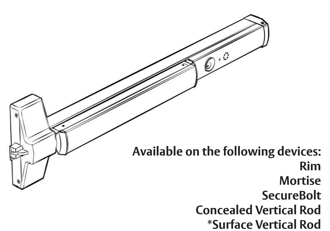
Delayed Egress
ED4000, ED5000 Series Exit Device

This product can expose you to lead which is known to the state of California to cause cancer and birth defects or other reproductive harm. For more information go to www.P65warnings.ca.gov.
*Rod Guards Required (made by other manufacturers)
ED4000, ED5000 Series Exit Device
Installation Instructions

| TOC | Table of Contents |
|---|---|
| 1 | Panic and Fire Rated Devices4 |
| a |
Checklist
4 |
| b |
Required Components
4 |
| c | Optional Components4 |
| d | Electrical Specifi cations4 |
| 2 | End Cover and PC Board Assembly5 |
| 3 | DIP Switch Settings6 |
| 4 | Installation of End Cover Asssembly to Device7 |
| 5 | Device Mounting8 |
| 6 | Wiring Layout: Input/Output Wiring Descriptions9 |
| 7 | ElectroLynx Connector System for All Electrical Installation 10 |
| 8 | ElectroLynx Wiring Options Overview with QC8 Hinge 11 |
| 9 | Installing Delayed Egress Exit Device 12 |
| 10 | ElectroLynx Wiring Options Overview with QC12 Hinge 13 |
| 11 |
ElectroLynx Wiring Deed: M93 Trim Monitor Option and QC12 Hinge
14 |
| 12 | ElectroLynx Wiring Deed: Electrifi ed Trim (ET) Option and QC12 Hinge 15 |
| 13 | ElectroLynx Wiring Deed: M91 Latchbolt Monitor Option and QC12 Hinge 16 |
| 14 | Non-ElectroLynx Door Prep 17 |
| 15 | Wiring Diagram: Single Door Exit Only 18 |
ED4000, ED5000 Series Exit Device
Installation Instructions

| TOC | Table of Contents |
|---|---|
| 16 | Wiring Diagram: Single Door with Remote Inputs & Monitoring Outputs 18 |
| 17 |
Wiring Diagram: M93 Trim Monitor Entry with External Door Position Switch
19 |
| 18 | Wiring Diagram: 9903 Electrical Trim Control 20 |
| 19 | Wiring Diagram: 9905 Electrical Trim Control 20 |
| 20 | Operating Instructions 21 |
| 21 | Additional Options Non ElectroLynx Wiring 22 |
| 22 |
BOCA 15 Second Delay M89 & BOCA 30 Second Delay M90
22 |
| 23 | NFPA 101 Requirements: 30 Second Delay M88 Suffi x 22 |
| 24 | Troubleshooting 23 |
| 25 | Appendix: Legacy Boards 25 |

Caution: Don't change factory applied fi nishes.
NOTE:
• Wiring method must be in accordance with CSA C22.1, Canadian Electrical Code, Part I, Safety Standard for Electrical Installations, Section 32; and CAN/ULC-S524 Installation of Fire Alarm Systems.
ED4000, ED5000 Series Exit Device
Installation Instructions

1 Panic and Fire Rated Devices
a Checklist
- 1. Check device for shipping damage prior to installation and make sure all parts are on hand.
- 2. Identify options provided with device.
- 3. Identify model, type and hand of trim if applicable (see exit device and trim instructions for reversing hands).
- 4. Contact hardware supplier if device is damaged or missing parts.
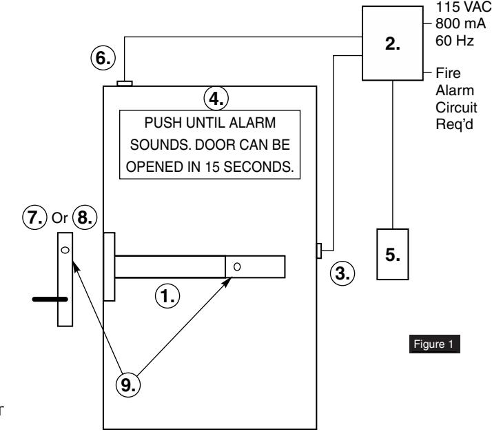
b Required Components (Numbered list correlates with numbers in Figure 1)
- 1. Delayed Egress Exit Device
- 2. 24VDC UL Listed Regulated and Filtered Power Supply with Fire Alarm Interface (recommend Securitron BPS 24-1 or 24-2 (UL294 Listed), depending on requirements). Power supply is NOT to be used in UL603 Burglar Alarm System.
- 3. Power transfer UL or ULC listed (2-10 wire depending on system)-Securitron (EPT) or equivalent.
- 4. Sign (MUST BE INSTALLED ON DOOR ABOVE DEVICE).
NOTE: The delayed egress system is to be installed in accordance with NFPA 101.
c Optional Components (Numbered list correlates with numbers in Figure 1)
- 5. Remote Annunciator
- 6. Door Position Switch (DPS)
- 7. Standard Trim
- 8. Electrified Trim
- 9. Device and Trim Cylinder
d Electrical Specifi cations*
Input Voltage 24VDC (+/-10%)
Wire Size:
18 AWG Min (up to 100')
Signal or Control 22AWG Min
Power Consumption:
Standard Device - 500mA
Device with Safe/Secure Electric Mortise or
Electric Trim Control - 1.5A
*Follow Local Electrical Codes for Wiring.
NOTE: Components shown do not refl ect all possible applications. Consult manufacturer for special applications.
ED4000, ED5000 Series Exit Device
Installation Instructions

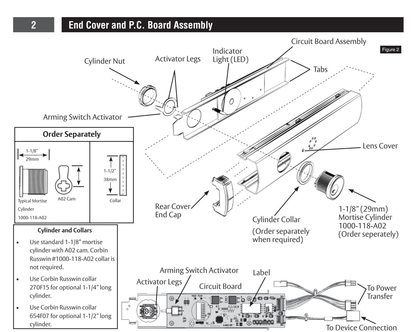
NOTES:
- Factory keyed orders will be shipped assembled.
- Prior to end cover assembly, device must be cut to proper length to prevent damage to circuit board. 36" Device cannot be field cut. A maximum of 6" can be cut from a 48" device.
- 1. Slide circuit board assembly into end cover. Front of assembly must be pulled away from cover to prevent damage to LED indicator light. Housing assembly is in correct position when LED can be inserted in lens cover on end cover. (Figure 2)
- 2. Insert cylinder (mortise and collar) into end cover with keyway horizontal and toward closest end of end cover.
- 3. Slide arming switch activator over cylinder so activator legs are on each side of switch.
- 4. Secure parts in place with cylinder nut. Be certain flange on cylinder nut inserts into arming switch activator to allow rotation of activator.
- 5. Verify assembly by rotating key counter-clockwise and clockwise. Key should move freely and arming switch should trip for both rotation directions. If key does not rotate freely, verify cylinder nut is in correct orientation. If arming switch does not trip, activator legs on arming switch activator can be bent to reduce or increase rotational travel.
ED4000, ED5000 Series Exit Device
Installation Instructions

3 DIP Switch Settings
S2-1: Nuisance Audible may be selected ON (default) or OFF.
S2-2 and S2-3: Nuisance Delay time may be selected 0 (Immediate), 1, 2, or 3 (default) seconds.
S2-4 and S2-5: Reset Delay time may be selected 5, 10 (default), 20 or 40 seconds.
S2-6: Whether an external LBM is used for not used for this product, the switch must be set ON (default) to Bypass. S2-6 OFF position is not used.
S2-7: Switch must be set ON (default) to Bypass when an external Door Position Switch (DPS) is NOT used, and OFF when an external DPS is used.
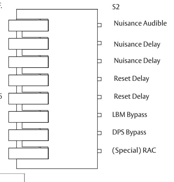
PCBA DIP SWITCH VIEW
| S2 DIP SWITCH - DEFAULT SETTINGS | ||||||||
|---|---|---|---|---|---|---|---|---|
| S2 DIP SW | 1 | 2 | 3 | 4 | 5 | 6 | 7 | 8 |
| OFF (UP) | OFF | OFF | ||||||
| DOWN (ON) | ON | ON | ON | ON | ON | ON | ||
| Nuisance Delay (seconds) | |||||
|---|---|---|---|---|---|
| 0 | 1 | 2 | 3 | ||
| S2-2 | OFF | OFF | ON | ON | |
| S2-3 | OFF | ON | OFF | ON | |
| Reset Delay (seconds) | |||||
| 5 | 10 | 20 | 40 | ||
| S2-4 | OFF | OFF | ON | ON | |
| S2-5 | OFF | ON | OFF | ON | |
| S2-6 | OFF | Not used |
|---|---|---|
| 32-0 | ON | LBM Bypass (always set ON) |
| S2-7 | OFF | External DPS is wired to device |
| 32-7 | ON | DPS Bypass, external DPS is NOT wired to device |
| S2-8 | OFF | Momentary egress mode 5, 10, 20, or 40sec, device will immediately Rearm After Closing (RAC) door if closed before selected time expires, or will enter alarm mode if time expires with door open. See other details** |
| ON | 40sec momentary egress mode is extended indefinitely if door is left open, then device immediately Rearms After Closing (RAC) door. See other details* |
* S2-8: When an external DPS is used and switch S2-8 ON, and 40 second reset delay (S2-4 and S2-5) are set ON, after activation of momentary egress by cylinder key switch or external remote reset signal, if the Door/DPS is open beyond 40sec the device will remain in momentary egress mode indefinitely and shall not enter alarm mode; then once the Door/DPS is closed it will rearm immediately.
If DPS is not used, is bypassed with S2-7 ON, the door will rearm immediately after 5, 10, 20 or 40 sec whether the door is open or closed, with either S2-8 ON or OFF.
Ensure eight S2 Dip Switches are set per application before moving on to the next page of instructions.
** With S2-8 OFF (S2-4 and S2-5 set for 5, 10, 20 or 40sec), if door/DPS is open after selected time the alarm will sound. Close door to reset and rearm device using cylinder key or remote reset signal. If door/DPS is opened then closed before selected time expires, the device will rearm immediately.
ED4000, ED5000 Series Exit Device
Installation Instructions

4 Installation of End Cover Assembly to Device
- 1. Turn end cover assembly over to circuit board side.
- 2. Ensure eight S2 Dip Switches are set for application (see previous page).
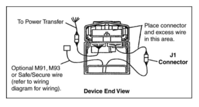
- 3. Slide end cover assembly into device, making sure not to pinch or crimp wires.
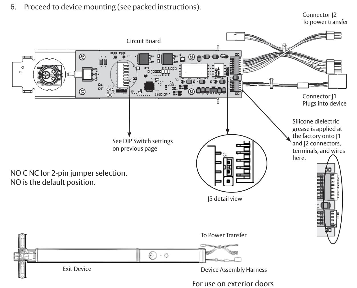
- 4. Connect device lock assembly harness to connector J1. Place wire connectors and excess wire between end cover and P.C. board. (Figure 3, Device End View)
- 5. Check all connections before proceeding.

NOTE:
• Review J5 Alarm Relay NO or NC selection above. If NC contact is required, remove PBCA/cover assembly from rail, move 2-pin jumper to NC, then re-install PCBA/cover on rail.
ED4000, ED5000 Series Exit Device
Installation Instructions

5 Device Mounting
- 1. Refer to installation instructions included with device and trim for complete door and frame preparations. Refer to template #T30890 for wire access hole location.
- 2. Feed wires from power transfer through wire access hole in door. (Figure 4)
- 3. When required, mount outside trim to door (see trim installation instructions).
- 4. Mount device to door (see device installation instructions).
- 5. Do not install end cap until device has been wired and tested for operation (See wiring diagrams).
- 6. Check mechanical operation and proceed to wiring diagrams.
NOTE: Wire nuts can be inserted into wire access hole after making connections. Quick disconnect can be used without removing wire nuts.
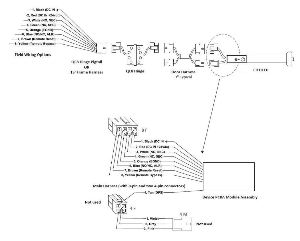
NOTE: For QC8 and QC12 ElectroLynx wiring, refer to Sections 8 and 10. ElectroLynx has pluggable connectors, wire nuts are not needed.
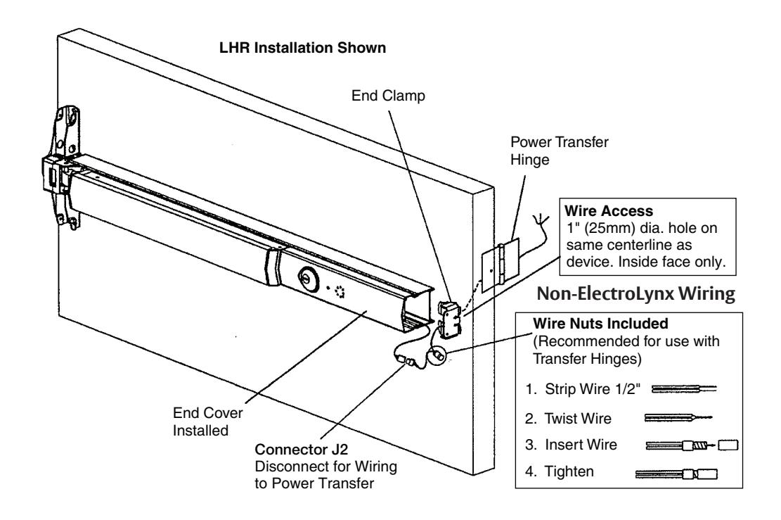
Figure 4
NOTES:
- Wires must be protected from abrasion.
- For use with Class II circuits only.
ED4000, ED5000 Series Exit Device
Installation Instructions

6 Wiring Layout: Input/Output Wiring Descriptions
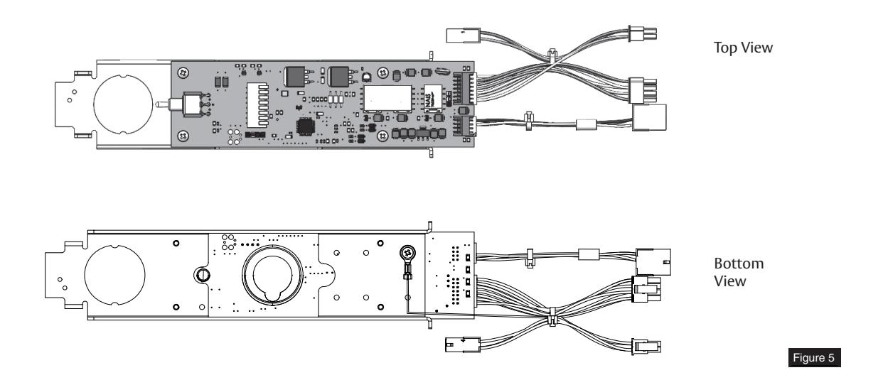
J2 Connector (See Figure 5 on next page) 8-Pin ElectroLynx Connector
| Pin Number | Input/Output | Wire Color | Description | Pin Number |
|---|---|---|---|---|
| 10 | Input | Black | 24VDC Power Supply (-Circuit Ground) | 1 |
| 12 | Input | Red | 24VDC Power Supply (+Positive) | 2 |
| 11 | Output | White |
Secure Relay Output - Normally Open (NO)
contact. Power off - contact is open Powered/armed - Relay energizes contact closes. After 15 or 30 seconds delay when device releases, the relay de-energizes, contact opens (same as Power off state). |
3 |
| 13 | Output | Green |
Secure Relay Output - Normally Closed (NC)
contact. Power off - contact is closed. Powered/armed - Relay energizes, contact opens. After 15 or 30 seconds delay when device releases, relay de-energizes, contact is closed (same as Power off state). |
4 |
| NC | EGND | Orange |
Earth Ground connection to PCB mounting plate
via ring terminal |
5 |
| 3 | Output | Blue |
Alarm Relay Output - J5 jumper Selectable
NO/NC contact that changes state when alarm cycle has been activated. Default shipped position - jumper is on NO contact setting. Power off - contact is NO or NC as per jumper selection.Powered/armed - Relay energizes contact reverses state. When alarm cycle is activated - Relay de-energizes (same as Power off state). |
6 |
| 8 | Input | Brown |
Remote Reset Input - Momentary input from
key switch, pushbutton, etc. Will release device for 5, 10, 20, or 40 seconds for egress or ingress and also reset device when in bypass or alarmed state. |
7 |
| 6 | Input | Yellow |
Remote Bypass Input - Momentary input
from key switch, pushbutton, etc. Will maintain device in an unlocked state for normal device operation. Device must be rearmed by resetting from key switch on device or remote reset. |
8 |
NOTE: ElectroLynx QC8 Hinge is only required if all eight wires are used. When DPS and any other wiring options are on the 4-pin connector, the hinge is NOT required.
NOTE: Secure and Alarm Relay contacts are rated max load 1A @24VDC.
ED4000, ED5000 Series Exit Device
Installation Instructions

6 Wiring Layout: Input/Output Wiring Descriptions, continued
J2 Connector (See Figure 5 below.)
4-Pin ElectroLynx Connector
| Pin Number | Input/Output |
Wire
Color |
Description | Pin Number |
|---|---|---|---|---|
| NC | Input/Output | Violet | C, LBM or C, Trim Mon. or ET(-) | 1 |
| NC | Input/Output | Gray | NO, LBM or NO, Trim Mon. or ET(+) | 2 |
| NC | Input/Output | Pink | NC, LBM or NC, Trim Mon. | 3 |
| 2 | Input | Tan |
Door Position Switch Input-Input sense for DPS
switch option |
4 |
NOTE: ElectroLynx QC12 Hinge is required if DPS and/or any options shown are required.
NOTE: Refer to Section 25 if replacing legacy PCBA/wiring with new PCBA/wiring.
7 ElectroLynx Connector System for All Electrical Installation
- 1. Mount exit device per instruction sheet provided.
- 2. Plug exit device connector into raceway connector in door. Feed through 1" (25mm) hole in door. Install rail mounting end clamp bracket with two (2) screws supplied. Install end cap.
-
3. Plug raceway connector from edge of door into electric hinge connector and feed wires back through door prep. Mount electric hinge to door.
- A. If wiring now, wire frame side wires, to wires on pigtail harness, on hinge as required by using connectors allowed by local code. Plug pigtail harness connector into electric hinge connector. Feed harness through frame prep and mount electric hinge.
- B. If wiring later, plug pigtail harness connector into electric hinge connector. Feed harness through frame prep and mount electric hinge.
ED4000, ED5000 Series Exit Device
Installation Instructions

7 ElectroLynx Connector System for All Electrical Installation, continued
Installation Notes:
- 1. Wiring to pigtail harness is per facility wiring requirement.
- 2. For an ElectroLynx system, go to function or monitor page(s) with your device.
- 3. Combinations of certain monitors can be used in each device. These instructions detail installation of each monitor separately.
ElectroLynx Connector System Notes:
System is designed to be installation friendly, with plug connectors from electric hinge through door to device. The only wiring required is loose wires on pigtail harness assembly on frame side of electric hinge (included with QC Hinge). Combinations of certain switches and monitors can be used.
The plug and receptacle connectors are designed to mate and lock together. Plug connectors into each other with locking mechanism aligned. Do NOT force connectors together any other way.
8 ElectroLynx Wiring Options Overview with QC8 Hinge
ED4000, ED5000 Series Exit Device
Installation Instructions

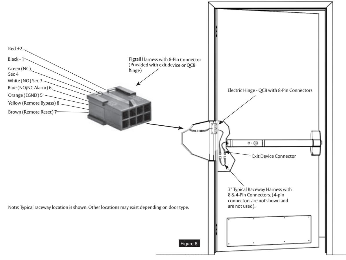
9 Installing Delayed Egress Exit Device
Refer to Figure 6 for delayed egress exit device installation wiring.
NOTE: For ElectroLynx Hinge Connector System: Follow Section 6 wiring instructions.
For non-ElectroLynx door:
Remove connector at end of exit device and connect to incoming wires from power source using wire nuts, butt splices, etc. See Section 14 for hole locations and sizes.

ED4000, ED5000 Series Exit Device
Installation Instructions

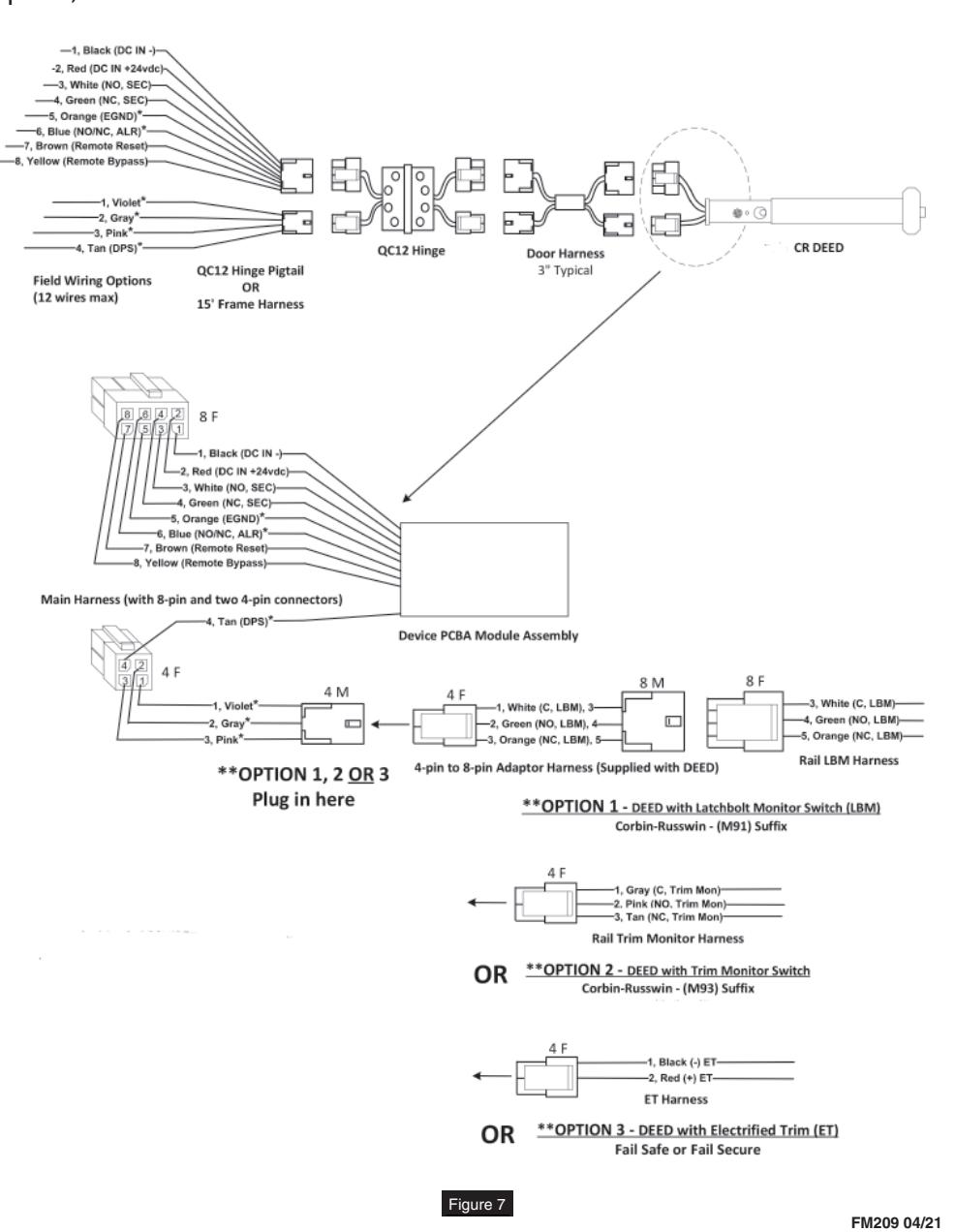
10 ElectroLynx Wiring Options Overview with QC12 Hinge
Refer to Figure 7 for M93 Monitor - Trim Actuated SPDT Switch wiring.
NOTE:
- Switch wiring max load: 2A @28VDC.
- Wire must be protected from abrasion.
- For use with Class II circuits only.
- For ElectroLynx QC12 Hinge Connector System: Follow Sections 11, 12, and 13 wiring instructions.
- For non-ElectroLynx door: Remove connector at end of exit device and connect to incoming wires from power source using wire nuts, butt splices, etc. See Section 14 for hole locations and sizes.
Note:
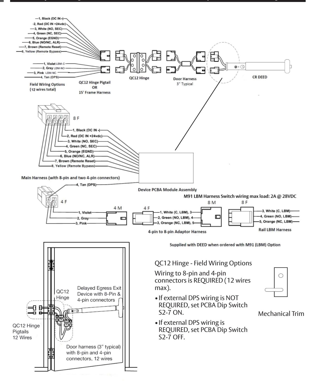
New wiring shown. Items followed by * indicate NEW PCBA wiring OR NEW DEVICE wiring that differs from Legacy wiring. Pluggable 4-pin connections from Device Harness to Main Harness is for new QC12 hinge wiring method.
QC12 Hinge - Wiring Options
Wiring to 8-pin and 4-pin connectors are REQUIRED (12 wires max)
- If external DPS wiring is REQUIRED (Set PCBA Dip Switch S2-7 OFF)
- If LBM, Trim Monitor, OR Electrified Trim Options are REQUIRED.
After routing two wires from ET through the chassis and the wire channel in back of rail then Install Molex Female 4-pin connector (supplied) onto pre-crimped female terminals ontoBlack wire pin 4-1, Red wire pin 4-2
For installation assistance contact Corbin Russwin 1-800-543-3658 • techsupport.corbinrusswin@assaabloy.com
ED4000, ED5000 Series Exit Device
Installation Instructions

11 ElectroLynx Wiring Deed with M93 Trim Monitor Option and QC12 Hinge
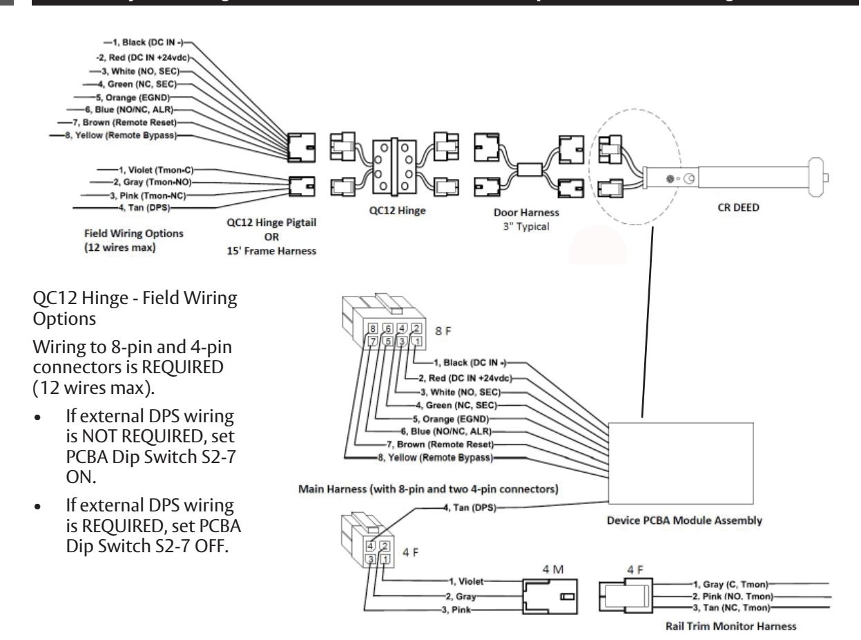
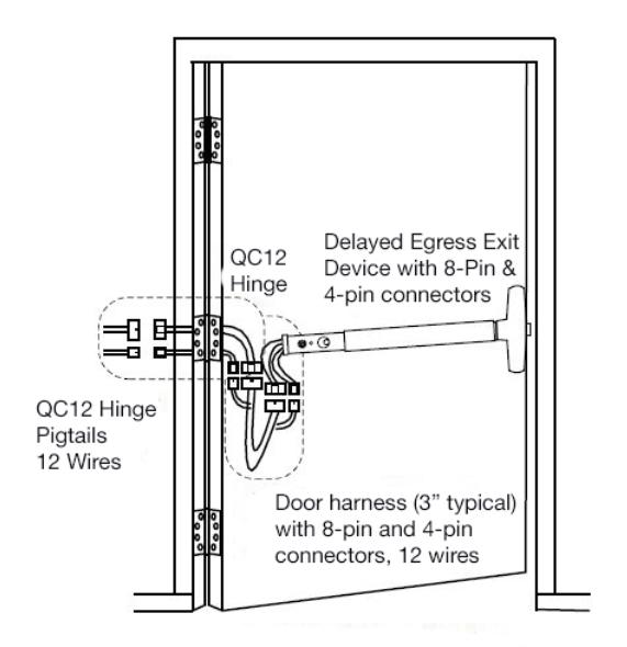
Supplied with DEED when ordered with M93 Trim Monitor (Tmon) Option
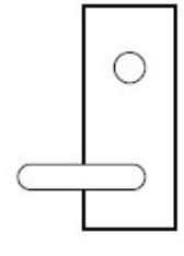
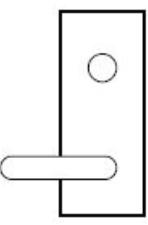
Mechanical Trim
ED4000, ED5000 Series Exit Device
Installation Instructions

12 ElectroLynx Wiring Deed with Electrifi ed Trim (ET) Option and QC12 Hinge
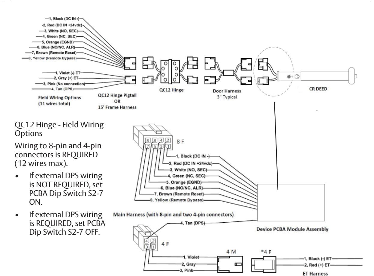
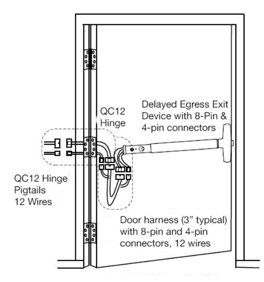
Supplied with DEED when ordered Fail Safe or Fail Secure Electrifi ed Trim (ET)
*Requires field to route two wires from ET through the chassis and the wire channel in back of rail then install loose Molex Female 4-pin(*4F) connector (supplied) onto pre-crimped female terminals onto Black wire pin 4-1, Red wire pin 4-2.
9903 Electrified Trim (ET) (SAF) Fail Safe Or 9905 Electrified Trim (ET) (SEC) Fail Secure
Installation Instructions

13 ElectroLynx Wiring Deed with M91 Latchbolt Monitor Option and QC12 Hinge
ED4000, ED5000 Series Exit Device
Installation Instructions

14 Non-ElectroLynx Door Prep
Refer to Figure 8 for non-ElectroLynx Door preparation.
NOTE:
- Do not scale drawing.
- Dimensions are in inches (") and millimeters (mm).
- LHR H.M. opening shown. Details are typical for all opening materials (both hands).
- This preparation is an addition to preparation shown on device template.
- See device template to locate centerline.
- Shields for wiring access recommended for insulated and composite doors.
- Locate and prepare wiring access holes when installing device.
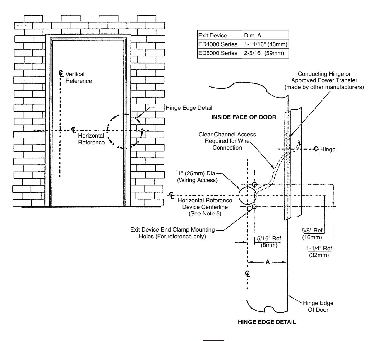
Figure 8
Installation Instructions

15 Wiring Diagram - Single Door Exit Only
Operation:
Mechanical trim can be added for entry. Ingress by trim without touching device push bar rim will not affect alarm if a door position switch is not being used. Refer to DPS wiring if necessary.
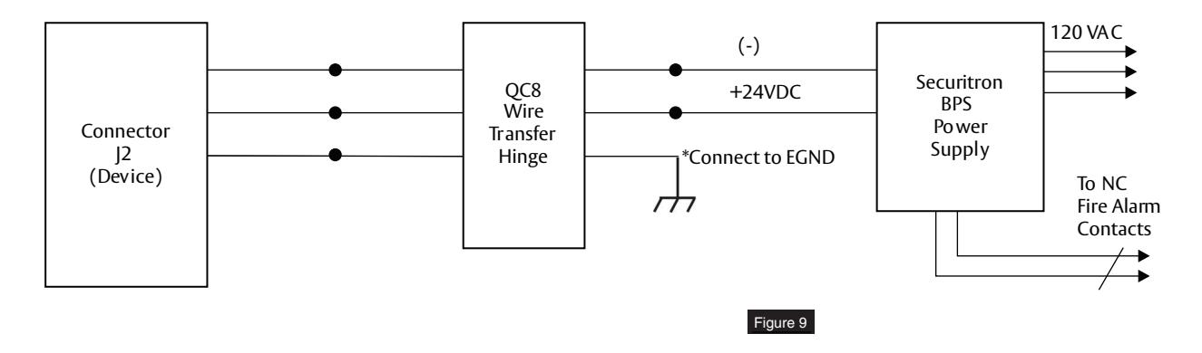
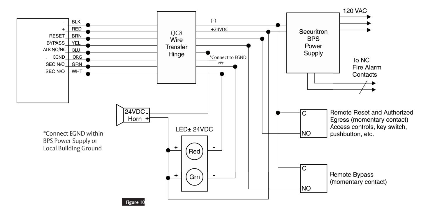
16 Wiring Diagram - Single Door With Remote Inputs & Monitoring Outputs
Operation:
Monitoring: Red LED indicates device is armed and secure. Activating device will sound alarm. (Figure 10) Green LED will illuminate after 15 seconds. Device will release for exit (unsecure).
NOTE: If dry contacts are needed for signaling or monitoring, a 24VDC relay is recommended.
ED4000, ED5000 Series Exit Device
Installation Instructions

17 Wiring Diagram - M93 Trim Monitor Entry with External Door Position Switch
* Door Position Switch (DPS) made by other manufacturers.
Operation:
Door Position Switch (DPS)* is used to activate alarm when door has been forced open. It also prevents device from being armed when door is propped open.
M93 trim monitor switch, when activated, will bypass unit and allow entry. Unit must be manually reset for rearming with cylinder key. (Figure 11)
NOTE: Requires M93 trim monitor switch on device for alarm shunting.
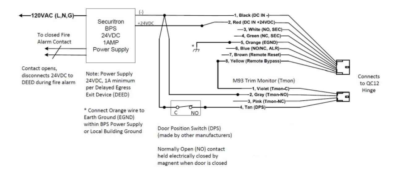
Figure 11
ED4000, ED5000 Series Exit Device
Installation Instructions

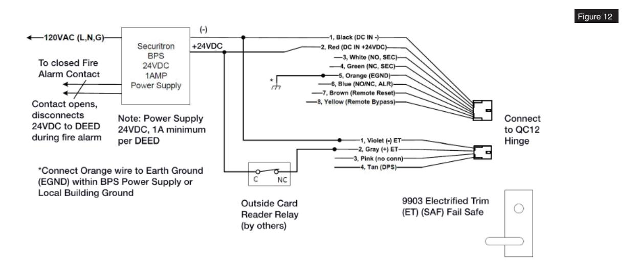
18 Wiring Diagram - 9903 Electric Trim Control
Operation:
Fail Secure (SAF) Trim allows normal access control for entry, and also allows entry during power failure or fire alarm activation. (Figure 12)
Electric trim operation will not affect armed device.
19 Wiring Diagram - 9905 Electric Trim Control
Operation:
Fail Secure (SEC) Trim allows access control for entry. Outside trim will remain locked during power failure or fire alarm activation. (Figure 13)
Electric trim operation will not affect armed device.
Figure 13
ED4000, ED5000 Series Exit Device
Installation Instructions

20 Operating Instructions
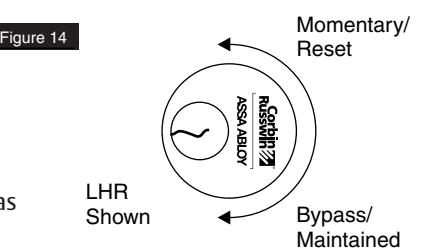
There are three (3) modes of operation (Figure 14):
- Delayed Egress
- Momentary Egress
- Bypass (Maintained) Egress
Delayed Egress Mode
- 1. Apply power to device. The initialization / self test sequence is as follows:
- Cover LED is RED for 2 seconds with horn sounding for 500ms.
- Cover LED is then GREEN for 2 seconds, followed by AMBER for 1 second with the 4 diagnositc LEDs illuminated.
- Cover LED is RED and green diagnostic LED is illuminated. The device is now armed, which will not allow pushpad to retract latchbolt for immediate egress.
- 2. If the device is not functioning, refer to the Troubleshooting Guide.
Momentary Egress Mode (Figure 14)
- 1. With device armed, rotate key counter clockwise and return to center position (remove key).
- 2. Red LED will flash quickly, approximately two times every second. Device will release for momentary egress for 10 seconds (factory set). 5, 10, 20 or 40 second reset delay may be selected using DIP switch positions 4 and 5.
- 3. After the reset delay time has elapsed, or if the cylinder key is rotated a second time counter clockwise during a reset delay, the device shall re-arm. When an external DPS is used and door is opened and closed during momentary egress, the selected reset delay shall be canceled and the device shall re-arm.
- 4. Device will now be back in delayed egress mode.
Bypass (Maintained) Egress Mode (Figure 14)
- 1. Rotate key clockwise, return key to center position and remove.
- 2. Red LED will flash slowly (one time every four seconds).
- 3. Device is disarmed, acting as a standard exit device which allows free egress.
Resetting device from Bypass Mode to Delayed Egress Mode (Figure 14)
- 1. Rotate key counter clockwise, return to center position and remove.
- 2. Solid red LED will illuminate.
- 3. Device will be in delayed egress mode.
Delayed Egress Operation When Armed
Exit door is normally closed and latched. Delayed Egress device secures door in locked mode with solid red LED indicating locked mode status. Depressing pushpad for three (3) seconds or less will sound device nuisance beeps, twice every 1.2 seconds without initiating alarm. Depressing pushpad longer than three (3) seconds will initiate an irreversible local audible alarm with a continuous tone, and a visual amber indicator. After delay time (15 or 30 seconds), device releases, LED changes to green, and the local audible alarm remains as a continuous tone until reset by keyswitch. Remote monitoring contact outputs can be used to alert security personnel. Person depressing pushpad is denied egress for 15 or 30 seconds (depending upon setup) and security personnel are alerted.
NOTE: 30 seconds may be accepted by local jurisdiction.
ED4000, ED5000 Series Exit Device
Installation Instructions

20 Operating Instructions, continued
Re-arm After Closing for Indefi nite Delay
With 40 second momentary egress setting (S2-4 ON & S2-5 ON), S2-8 ON, and an external DPS is wired to the PCBA-after activation of momentary egress by cylinder key switch or external remote reset signal, if the Door/ DPS is open beyond 40 seconds, it will remain in momentary egress mode indefinitely and shall not enter alarm mode. Then once the Door/DPS is closed, it will re-arm immediately. With (S2-4 ON & S2-5 ON) S2-8 OFF for same scenario as above, the device will enter alarm mode after 40 seconds if the Door/DPS is still open. If Door/ DPS is closed before 40 seconds, it will re-arm immediately.
21 Additional Options Non ElectroLynx Wiring
Electrically Controlled Trim (Mortise Device) "Safe/Secure"
The Delayed Egress Exit Device is available with Fail Safe (SAF) or Fail Secure (SEC) outside trim operation. In a fire condition, the Fail Safe trim will release for entry. When Access control is used, the Fail Secure trim allows entry by means of a remote card reader, keyswitch, push button, etc.
Note: If a Door Position Switch is not used, the trim will open the door without affecting the device in an armed condition (refer to wiring diagrams for wiring).
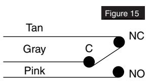
Outside Trim Monitor Switch (M93) Suffi x
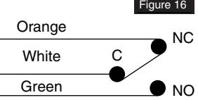
Latchbolt Monitor Switch (M91) Suffi x
This option is used when outside trim is desired to be used with an external Door Position Switch (by others). This switch will allow bypass (disarms device) when the trim is used for ingress. The device will need to be reset upon entry by means of the keyswitch on the device or a remote SPDT switch (refer to wiring diagrams for wiring).
Note: If an external DPS is not used, Standard trim and Safe/Secure trim will allow entry without affecting the device in an armed mode. The device will only be affected when the push pad is depressed. Latchbolt monitor switch is a SPDT switch that monitors security of latchbolt or vertical rods.
22 BOCA 15 Second Delay M89 and BOCA 30 Second Delay M90
Upon depressing the pushpad for 1 second or longer, the device will sound an audible continuous tone and allow the door to be opened within 15 (or 30) seconds. The alarm will remain as a continuous tone until reset. Resetting of the alarm and re-arming of the device occurs automatically once the door has been returned to the closed position for 30 seconds. The 30-second re-arming timer will re-start if the pushpad is depressed or the door is re-opened before actual re-arming of the device occures. A DPS (Door Position Switch) is required for the BOCA option.
NOTE: BOCA option is not suitable for installations in accordance with NFPA 101.
23 NFPA 101 Requirements: 30 Second Delay M88 Suffi x
Upon depressing the pushpad for 3 seconds or longer, the device will sound an audible continuous tone and allow the door to be opened after 30 seconds. The alarm will remain as a continous tone until reset. Resetting of the alarm and re-arming of the device is accomplished by manual means only.
ED4000, ED5000 Series Exit Device
Installation Instructions

24 Troubleshooting
| Problem | Solution |
|---|---|
|
Power is applied, but
unit will not arm (No red LED). |
• Check all connections on circuit board and wire harness.
• Check for power 24VDC at power inputs (-black) and (+red) and check polarity. • Check wire transfer for any bad connections or broken wires. • Check power output at power supply. • Must be 24VDC regulated. |
| Device alarms contin | • Check trigger mechanism wire harness on circuit board and all other |
| uously when power is | connections. |
| applied. | • Check pushpad activating switch in device. |
| Units with Door Position | • Make sure DPS is wired (electrically closed - with door closed) into wire |
| Switch (made by other | harness. Make sure DPS is working properly by using a meter to check |
| manufacturers). | continuity when door is opened and closed. |
|
Device allows mechan
ical latchbolt retraction with power applied and LED shows armed. |
• Check for correct power, 24VDC regulated.
• Check for correct amperage on power supply (must be rated equal or greater than device, 500mA minimum). |
| Exit device latchbolt/rods | • Refer to standard exit device installation instructions troubleshooting |
| will not latch properly. | guide. |
NOTE: If device is not working properly after troubleshooting, contact your local hardware distributor or local Corbin Russwin representative, or contact Corbin Russwin.
ED4000, ED5000 Series Exit Device
Installation Instructions

24 Troubleshooting, continued
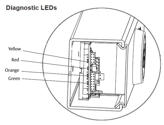
Refer to the following table and notes for an explanation of each LED's function.
| Diagonistic LEDs | Function |
|---|---|
| Yellow |
ON - LBM Bypass DIP switch position 7 is OFF-set ON
OFF- LBM Bypass DIP switch position is ON (normal operation) |
| Red (Push Rail Switch) |
ON- Rail Push Bar is depressed.
OFF- Rail Push Bar is released. |
| Orange (Door Status Switch) |
ON- Door Status Switch is open. Door is open/violated.
OFF- Door Status Switch is closed or DPS Bypass DIP switch position 6 is ON. |
| Green (Solenoid) |
ON- Rail Solenoid is energized. (+24 VDC from main board)
OFF- Rail Solenoid is de-energized. |
NOTES:
- 1. When the rail is armed (in Delayed Egress Mode) and the door is closed and latched, the Red End Cover LED and the Green Diagnostic LED should be ON only. All other LEDs should be OFF.
- 2. With the rail armed, depressing the rail push bar slightly will turn the Red Diagnostic LED ON. The rail should go into alarm immediately (no nuisance delay) or after being pressed for 1, 2, or 3-second nuisance delay setting. The rail will be in the irreversible alarm mode - End Cover LED is Amber with local audible beeping tone. After a standard delay of 15 seconds (0r 30-second optional delay), the rail solenoid de-energizes and passage is allowed. End cover LED is green with alarm at a steady tone which continues until reset by key switch.
- 3. When a Door Status switch is used and the door is opened, the Orange Diagnostic LED will turn ON, which indicates that the door is not closed. When not using a door status switch, DIP switch position 7 must be set to ON, Orange Diagnostic LED shall be off.
ED4000, ED5000 Series Exit Device
Installation Instructions

25
Appendix: Legacy Boards
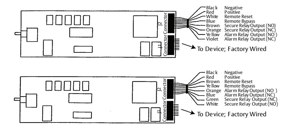
There were two versions of legacy printed circuit boards where the wire colors, alarm, and secure relay connections differed. Please refer to the below diagrams as a reference, if needed.
ED4000, ED5000 Series Exit Device
Installation Instructions

ED4000, ED5000 Series Exit Device
Installation Instructions


Corbin Russwin 225 Episcopal Road Berlin, CT 06037 Phone: 800-543-3658