Corbin Russwin ED4000 Series Exit Devices Catalog_45060
Open the original PDF document
View PDF

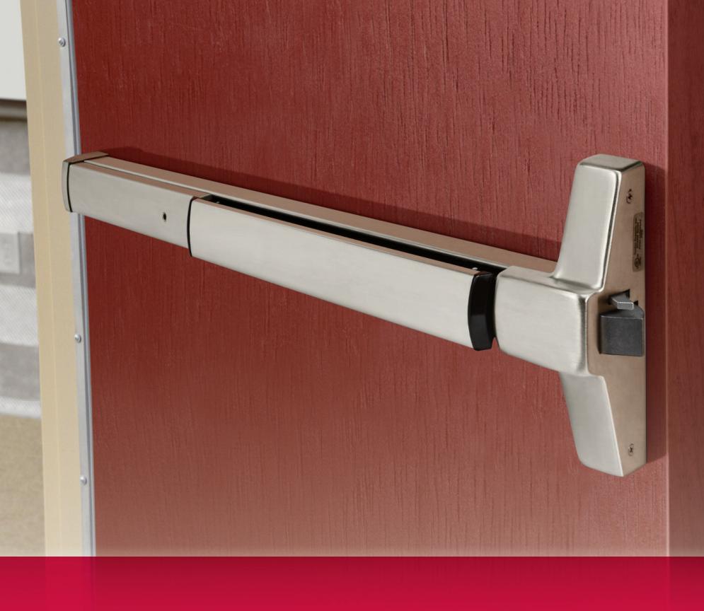

ED4000 Series


Product Catalog

Introduction
ED4000 Series
Table of Contents
| Applications 2 |
| Applications and Listings 3 |
| Functions 4 |
| SecureBolt® Features 6 |
| Rim Features 8 |
| Surface Vertical Rod Features 10 |
|
Concealed Vertical
Rod Features 12 |
| Trims and Functions 14 |
| Electrified Exit Devices 19 |
| Mullions 32 |
| Options and Accessories 33 |
| Cylinders 35 |
| How to Order 36 |
| Quick Codes 38 |
| Facts and Figures 40 |
| Helpful Terms 41 |
| How to Specify 42 |
www.corbinrusswin.com
Applications
Designed for applications on narrow stile full glass, aluminum and metal doors in high-use and high-abuse situations, ED4000 Series devices can be teamed with a variety of Corbin Russwin trims to provide desired functions, styles and fi nishes in new construction and renovations, including:
- Schools and universities
- Health care facilities
- Government and municipal buildings
- Factories and warehouses
- Offi ce and retail complexes
- Transportation facilities
- Hotels and conference centers
- Religious facilities
- Theaters and auditoriums
Advantages
- Meets ANSI Grade 1 requirements
- Easy-to-use pushpad for quick egress and ADA compliance
- Low projection for barrier-free code compliance
- Heavy-duty construction
- Quiet operation
- Closed on all sides no projecting parts to inhibit egress
- Devices accommodate various function trims for fl exibility
- Through-bolted trims for strength, security, durability, smooth operation and easy installation
- Wide range of designs and fi nishes to match other Corbin Russwin products
- One-point dogging
- Devices satisfy UL/cUL safety requirements

Applications and Listings
ED4000 Series
| Single Door | UL Listing |
Maximum
Opening (W x H) |
Application | |
|---|---|---|---|---|
| Rim | ||||
| ED4200 | Panic | 4' x * | Surface applied; single-point latching. | |
| ED4200M | Panic | 4' x * | Surface applied single-point latching. | |
| ED4200MA | 3Hr. | 4' x 8' | Surface applied single-point latching. | |
| SecureBolt® | ||||
| ED4200S | Panic | 4' x * | Surface applied; single-point latching. | |
| ED4200SM | Panic | 4' x * | Surface applied single-point latching. | |
| ED4200SMA | 3Hr. | 4' x 8' | Surface applied single-point latching. | |
| Surface Vertical Rod | ||||
| ED4400 | Panic | 4' x 10' | Surface applied; two-point latching. | |
| ED4400M | Panic | 4' x 10' | Surface applied two-point latching. | |
| ED4400MA | 3Hr. | 4' x 10' | Surface applied two-point latching. | |
| Concealed Vertical Rod | ||||
| ED4800 | Panic | 4' x 10' | Rods concealed in door; two-point latching. | |
| ED4800M | Panic | 4' x 10' | Rods concealed in door two-point latching. | |
| ED4800MA | 3Hr. | 4' x 10' | Rods concealed in door two-point latching. | |
| Pair of Doors with Removable Mullion | UL Listing |
Maximum
Opening (W x H) |
Application | |
| Rim x Rim | ||||
| ED4200 x ED4200 x CR808 | Panic | 8' x 8' | Two independent active doors with removable mullion. | |
| ED4200M x ED4200M x CR908 | Panic | 8' x 8' | Two independent active doors with removable mullion. | |
| ED4200MA x ED4200MA x CR908A | 3Hr. | 8' x 8' | Two independent active doors with removable mullion. | |
| SecureBolt® x SecureBolt® | ||||
| ED4200S x ED4200S x CR808 | Panic | 8' x 8' | Two independent active doors with removable mullion. | |
| ED4200SM x ED4200SM x CR908 | Panic | 8' x 8' | Two independent active doors with removable mullion. | |
| ED4200SMA x ED4200SMA x CR908A | 3Hr. | 8' x 8' | Two independent active doors with removable mullion |
Note: All ED4000 Series Narrow Stile Pushpad Exit Devices are UL305 panic listed.
* UL does not set a door height limitation on panic applications.

Applications and Listings
ED4000 Series
| Pair of Doors | UL Listing |
Maximum
Opening (W x H) |
Application |
|---|---|---|---|
| Surface Vertical Rod | |||
| ED4400 x ED4400 | Panic | 8' x 10' |
Two independent doors with two-point latching, swing
ing in the same direction. |
| ED4400M x ED4400M | Panic | 8' x 10' |
Two independent doors with two-point latching, swing
ing in the same direction. |
| ED4400MA x ED4400MA | 3Hr. | 8' x 10' |
Two independent doors with two-point latching, swing
ing in the same direction. |
| Surface Vertical Rod (Double Egress) | |||
| ED4400 x ED4400 | Panic | 8' x 10' |
Two independent doors with two-point latching, swing
ing in opposite directions. |
| ED4400M x ED4400M | Panic | 8' x 10' |
Two independent doors with two-point latching, swing
ing in the same direction. |
| ED4400MA x ED4400MA | 3Hr. | 8' x 10' |
Two independent doors with two-point latching, swing
ing in the same direction. |
| Concealed Vertical Rod | |||
| ED4800 x ED4800 | Panic | 8' x 10' |
Two independent doors with two-point latching,
swinging in the same direction. |
| ED4800M x ED4800M | Panic | 8' x 10' |
Two independent doors with two-point latching, swing
ing in the same direction. |
| ED4800MA x ED4800MA | 3Hr. | 8' x 10' |
Two independent doors with two-point latching, swing
ing in the same direction. |
| Concealed Vertical Rod (Double Egress) | |||
| ED4800 x ED4800 | Panic | 8' x 10' |
Two independent doors with two-point latching, swing
ing in the opposite direction. |
| ED4800M x ED4800M | Panic | 8' x 10' |
Two independent doors with two-point latching, swing
ing in the same direction. |
| ED4800MA x ED4800MA | 3Hr. | 8' x 10' |
Two independent doors with two-point latching, swing
ing in the same direction. |
Note: All ED4000 Series Narrow Stile Pushpad Exit Devices are UL305 panic listed.
* UL does not set a door height limitation on panic applications.

Functions
ED4000 Series
Exit Only, Pull and Thumbpiece Trims
|
Rim/SecureBolt®
ED4200 ED4200S Inside Outside |
Surface
Vertical Rod ED4400 Inside Outside |
Concealed Vertical
Rod ED4800 Inside Outside |
Туре | ANSI No. | Function Description |
|---|---|---|---|---|---|
| 0 | Exit Only | 01 | Exit only; no trim. | ||
| Dummy | 02 | Entrance by trim when actuating bar is locked down. | |||
| Nightlatch | 03 | Entrance by trim when latchbolt is retracted by key. Key removable only when locked. | |||
| Classroom* | 05 | Entrance by thumbpiece. Key locks or unlocks thumbpiece. | |||
| Passage | 15 | Entrance by trim when latch is released by thumbpiece. Thumbpiece is always active, no cylinder. | |||
|
Storeroom
(Thumbpiece Active) |
06 | Entrance by thumbpiece only when released by key. Key removable only when locked. |

Overview
ED4000 Series
Knob, Lever and Thumbturn Trims
|
Rim/SecureBolt®
ED4200 ED4200S Inside Outside |
Surface
Vertical Rod ED4400 Inside Outside |
Concealed Vertical
Rod ED4800 Inside Outside |
Туре | ANSI No. | Function Description |
|---|---|---|---|---|---|
| Dummy | 02 | Entrance by trim when actuating bar is locked down. | |||
| Classroom* | 08 | Entrance by knob or lever. Key locks or unlocks knob or lever. | |||
| Passage | 14 | Entrance by trim when latchbolt is released by knob or lever. Knob or lever always active, no cylinder. | |||
|
Storeroom (Grip
Active) |
09 | Entrance by knob or lever only when released by key. Key removable only when locked. | |||
| Classroom* | 11 | Entrance by control turn piece. Key locks or unlocks control. | |||
| Passage | 16 | Latchbolt retracted by thumbturn. |
* Classroom function trims can be converted to Storeroom function by a simple field adjustment.

SecureBolt® Features
ED4000 Series
ED4200S Narrow Stile SecureBolt® Exit Device

Handing
Device non-handed. Trim handed.
Bar Length
Easily fi eld cut to size.
Standard: 36" (914mm) bar fi ts 30"- 36"
(762mm-914mm) door.
Optional: 24" (610mm) bar fi ts 24" (610mm) door; specify W024.
Optional: 48" (1219mm) bar fi ts 36"- 48" (914mm-1219mm) door; specify W048.
Door Thickness
1-3/4" (44mm) standard. Optional: 2" (51mm); specify D200. Optional: 2-1/4" (57mm); specify D214.
Stile
Minimum width 2" (51mm).
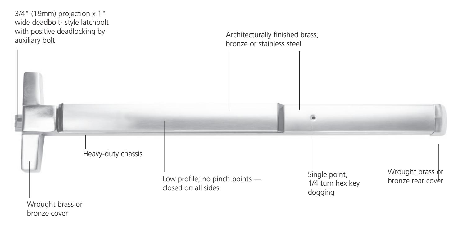
Deadbolt
Full 3/4" (19mm) projection, 1" (25mm) wide , positive deadlocking by auxiliary bolt.
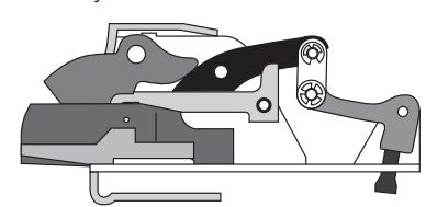
Cutaway Side View
Materials
High-grade, heat-treated, corrosion-resistant nickel steel alloy. Finished parts are brass, bronze or stainless steel; stainless steel springs; nylon bearings.
Latchbolt
Stainless steel. Slide action deadbolt with positive deadlocking by auxiliary bolt. Twopiece deadbolt mechanism utilizing a rollback lever which eliminates any contact (friction) with the strike during relocking.
Projection
3-1/4" (83mm) active, 2-3/4" (70mm) dogged.
Standard: single-point 1/4 turn hex key dogging.
Optional: less dogging; specify M51. Optional: cylinder dogging; specify M52. Optional: electric dogging, specify M97.
Fasteners
Standard: machine screws.
Optional: sex nuts and bolts; specify M54.
Strike
Surface mounted 3/8" (10mm) diameter roller strike, complete with positive locking plate and shims, ensuring low-friction relocking for a long, trouble-free life.
Functions and Trims
Through-bolted lever, knob, pull, thumbturn and thumbpiece trims available with wide range of functions; see Trims and Functions, page 14.
Cylinders
Cylinder not included unless specifi ed. See Quick Codes, page 38.
Removable Mullion
See Mullions, page 32.
Shim Kit
Optional for mounting device over raised vision light molding; specify M58.
Applications and Listings
See page 3.
Warranty
Five-year limited.
ANSI
Meets A156.3, Type 4 or 28, Grade 1. Meets A117.1 Accessibility Code.
UL/cUL
All devices listed for safety as panic hardware; devices comply with UL 305 standards for panic hardware. UL symbol on active case cover indicates listing.
California State Reference Code
This product has been approved by the California State Fire Marshal pursuant to section 13144.1 of the California Health and Safety Code.
NFPA
All exit devices comply with NFPA 101 Life Safety Code.
ADA
Exit devices, lever trims and pulls comply with Americans with Disabilities Act.
Finishes BHMA 605 Bright Brass BHMA 606 Satin Brass BHMA 611 Bright Bronze BHMA 612 Satin Bronze BHMA 613 Oxidized Bronze, oil rubbed, available lacquered BHMA 613E Dark Oxidized Satin Bronze Equivalent BHMA 618 Bright Nickel Plated BHMA 619 Satin Nickel Plated BHMA 625 Bright Chromium Plated BHMA 6261 (Trim Only) Satin Chromium Plated 626C2 Satin Chromium Plated with MicroShield® BHMA 629 Bright Stainless Steel BHMA 630 Satin Stainless Steel 630C2 Satin Stainless Steel with MicroShield® 722 Black oxidized bronze,oil rubbed BSP Black Suede Powder Coat WSP White Suede Powder Coat
- 1. Contact factory for devices required in BHMA 626.
- 2. Finish available with MicroShield® antimicrobial coating.
Copyright © 2001-2023, ASSA ABLOY Access and Egress Hardware Group, Inc. All rights reserved. Reproduction in whole or in part without the express written permission of ASSA ABLOY Access and Egress Hardware Group, Inc. is prohibited. Patent pending and/or patent www.assaabloydss.com/patents.

SecureBolt® Features
ED4000 Series
ED4200S SecureBolt® Exit Device
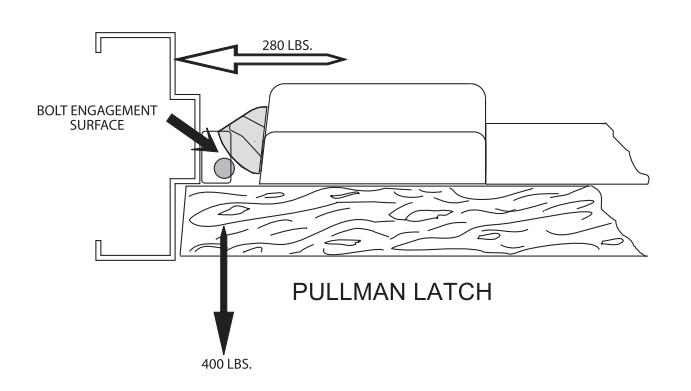
Vector Forces
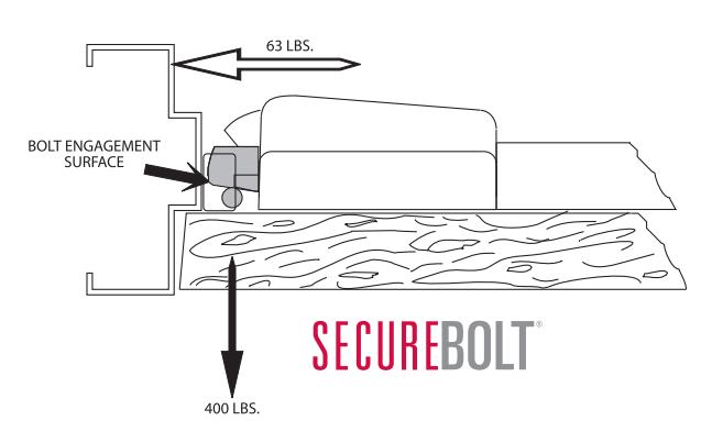
In terms of an exit device, vector forces mean that pressure applied to the door results in a force against the stop and the frame, resulting in door/frame separation. The standard pullman latchbolt applies 280 pounds of force against the frame from a 400- pound pull on the door.
The SecureBolt® exit device only applies 63 pounds of force against the frame from a 400-pound pull on the door. Less force means the door and frame do not separate, providing a higher level of security, as the door cannot be pulled open.

Rim Features
ED4000 Series
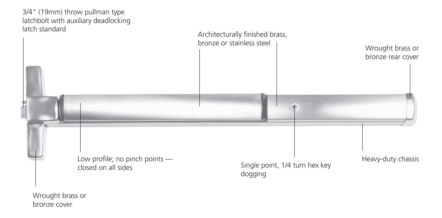
ED4200 Narrow Stile Rim Exit Device

Features Handing
Device non-handed. Trim handed.
Bar Length
Easily fi eld cut to size.
Standard: 36" (914mm) bar fi ts 30"- 36"
(762mm-914mm) door.
Optional: 24" (610mm) bar fi ts 24"
(610mm) door; specify W024. Optional: 48" (1219mm) bar fi ts 36"- 48"
(914mm-1219mm) door; specify W048.
Door Thickness
1-3/4" (44mm) standard. Optional: 2" (51mm); specify D200. Optional: 2-1/4" (57mm); specify D214.
Stile
Minimum width 2" (51mm).
Latchbolt
3/4" (19mm) throw, pullman type with stainless steel deadlocking latch.
Materials
Heavy-duty cold-forged steel chassis; heavy-gauge steel mechanisms, electroplated for corrosion resistance; fi nished parts are brass, bronze or stainless steel; stainless steel springs; nylon bearings.
Projection
3-1/4" (83mm) active, 2-3/4" (70mm) dogged.
Dogging
Standard: single point 1/4 turn hex key dogging.
Optional: less dogging; specify M51. Optional: cylinder dogging; specify M52. Optional: electric dogging; specify M97.
Fasteners
Standard: machine screws.
Optional: sex nuts and bolts; specify M54.
Strike
Surface mounted 3/8" (10mm) diameter roller strike, complete with positive locking plate and shims.
Functions and Trims
Through-bolted lever, knob, pull, thumbturn and thumbpiece trims available with wide range of functions; see Trims and Functions, page 14.
Cylinders
Cylinder not included unless specifi ed. See Quick Codes, page 38.
Removable Mullion
See Mullions, page 32.
Shim Kit
Optional for mounting device over raised vision light molding; specify M58.
Applications and Listings
See page 3.
Warranty
Five-year limited.
Certifi cation/Compliance ANSI
Meets A156.3, Type 4, Grade 1. Meets A117.1 Accessibility Code.
UL/cUL
All devices listed for safety as panic hardware; devices comply with UL 305 standards for panic hardware. UL symbol on active case cover indicates listing.
California State Reference Code
This product has been approved by the California State Fire Marshal pursuant to section 13144.1 of the California Health and Safety Code.
NFPA
All exit devices comply with NFPA 101 Life Safety Code.
ADA
Exit devices, lever trims and pulls comply with Americans with Disabilities Act.
ED4200M & ED4200MA
The ED4200M and ED4200MA rim exit device provides the appearance of a narrow stile rim exit device for use on wide stile or fl ush doors. Using the ED4200M or ED4200MA with narrow stile trim provides design continuity and pleasing aesthetics when matching exit devices for inside doors to outside narrow stile doors.
Finishes
| BHMA 605 | Bright Brass |
|---|---|
| BHMA 606 | Satin Brass |
| BHMA 611 | Bright Bronze |
| BHMA 612 | Satin Bronze |
| BHMA 613 |
Oxidized Bronze, oil rubbed,
available lacquered |
| BHMA 613E |
Dark Oxidized Satin Bronze
Equivalent |
| BHMA 618 | Bright Nickel Plated |
| BHMA 619 | Satin Nickel Plated |
| BHMA 625 | Bright Chromium Plated |
|
BHMA 626*
(Trim Only) |
Satin Chromium Plated |
| 626C |
Satin Chromium Plated
with MicroShield® |
| BHMA 629 | Bright Stainless Steel |
| BHMA 630 | Satin Stainless Steel |
| 630C |
Satin Stainless Steel
with MicroShield® |
| 722 | Black oxidized bronze,oil rubbed |
| BSP | Black Suede Powder Coat |
| WSP | White Suede Powder Coat |
*Contact factory for devices required in BHMA 626

Rim Features
ED4000 Series
ED4200 Narrow Stile Rim Exit Device

Surface Vertical Rod Features
ED4000 Series
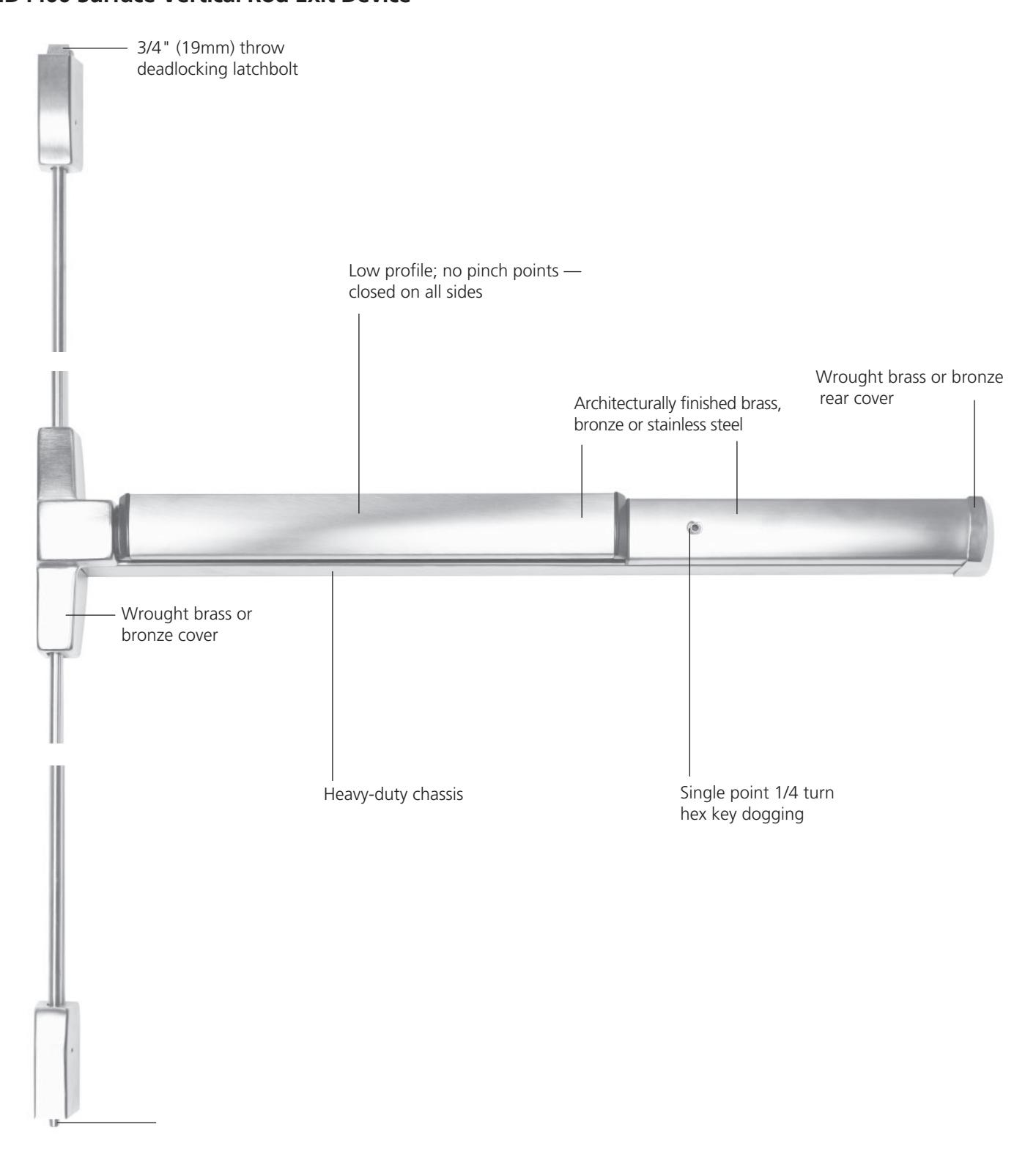
ED4400 Narrow Stile Surface Vertical Rod Exit Device
Features
Handing
Device is handed but easily fi eld reversible. Trim handed.
Bar Length
Easily fi eld cut to size.
Standard: 36" (914mm) bar fi ts 30"- 36"
(762mm-914mm) door.
Optional: 24" (610mm) bar fi ts 24"
(610mm) door; specify W024.
Optional: 48" (1219mm) bar fi ts 36"- 48" (914mm-1219mm) door; specify W048.
Door Thickness
1-3/4" (44mm) standard.
Optional: 2" (51mm); specify D200.
Optional: 2-1/4" (57mm); specify D214.
Stile
Minimum width 2" (51mm).
Door Height
Standard: Top rod for 7' door. All top rods easily fi eld cut to size. Optional door heights available; see Quick Codes, page 38.
Latchbolt
Top: 3/4" (19mm) throw, pullman type with automatic deadlatching. Bottom: 5/8" (16mm) throw deadbolt,
held retracted during door swing.
Vertical Rods
1/2" O.D. tubular brass, bronze or stainless steel with rod guides.
Materials
Heavy-duty cold-forged steel chassis; heavy-gauge steel mechanisms, electroplated for corrosion resistance; fi nished parts are brass, bronze or stainless steel; stainless steel springs; nylon bearings.
Projection
3-1/4" (83mm) active, 2-3/4" (70mm) dogged.
Dogging
Standard: single point 1/4 turn hex key
dogging.
Optional: less dogging; specify M51. Optional: cylinder dogging; specify M52. Optional: electric dogging; specify M97.
Fasteners
Standard: machine screws.
Optional: sex nuts and bolts; specify M54.
Strike
Top: Adjustable roller strike with positive
locking plate and shims. Bottom: fl ush mounted.
Optional strikes available; see Options and
Accessories, page 34.
Functions and Trims
Through-bolted lever, knob, pull, thumbturn and thumbpiece trims available with wide range of functions; see Trims and Functions, page 14.
Cylinders
Cylinder not included unless specifi ed. See Quick Codes, page 38.
Shim Kit
Optional for mounting device over raised vision light moding; specify M58.
Applications and Listings
See page 3.
Warranty
Five-year limited.
Certifi cation/Compliance ANSI
Meets A156.3, Type 5, Grade 1.
UL/cUL
All devices listed for safety as panic hardware; devices comply with UL 305 standards for panic hardware. UL symbol on active case cover indicates listing.
California State Reference Code
This product has been approved by the California State Fire Marshal pursuant to section 13144.1 of the California Health and Safety Code.
NFPA
All exit devices comply with NFPA 101 Life Safety Code.
ADA
Lever trims and pulls comply with Americans with Disabilities Act.
Finishes
| BHMA 605 | Bright Brass | |
|---|---|---|
| BHMA 606 | Satin Brass | |
| BHMA 611 | Bright Bronze | |
| BHMA 612 | Satin Bronze | |
| BHMA 613 |
Oxidized Bronze, oil rubbed,
available lacquered |
|
| BHMA 613E |
Dark Oxidized Satin Bronze
Equivalent |
|
| BHMA 618 | Bright Nickel Plated | |
| BHMA 619 | Satin Nickel Plated | |
| BHMA 625 | Bright Chromium Plated | |
|
BHMA 626*
(Trim only) |
Satin Chromium Plated | |
| 626C |
Satin Chromium Plated
with MicroShield® |
|
| BHMA 629 | Bright Stainless Steel | |
| BHMA 630 | Satin Stainless Steel | |
| 630C |
Satin Stainless Steel
with MicroShield® |
|
| 722 | Black oxidized bronze,oil rubbed | |
| BSP | Black Suede Powder Coat | |
| WSP | White Suede Powder Coat | |
*Contact factory for devices required in BHMA 626

Surface Vertical Rod Features
ED4000 Series
ED4400 Surface Vertical Rod Exit Device

Concealed Vertical Rod Features
ED4000 Series
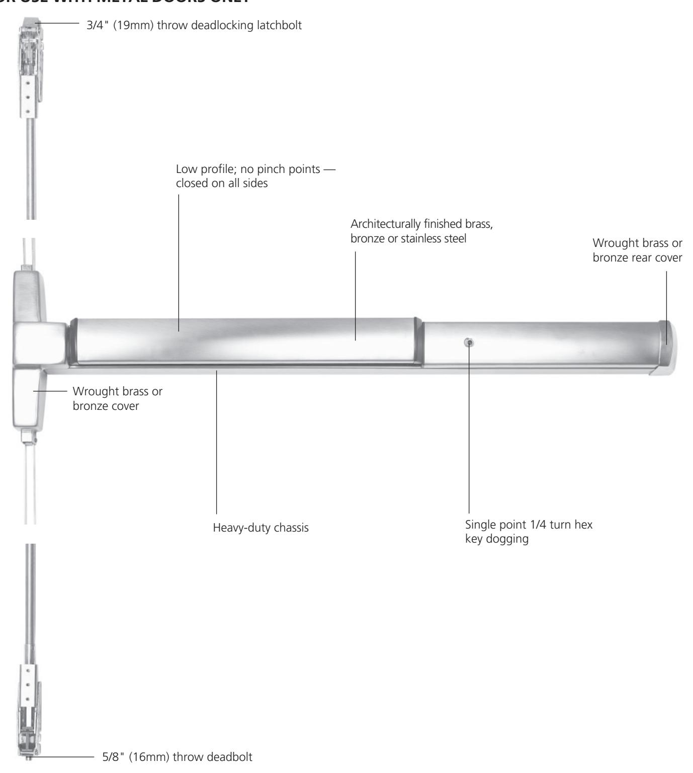
ED4800 Narrow Stile Concealed Vertical Rod Exit Device FOR USE WITH METAL DOORS ONLY

Features
Handing
Device handed but easily fi eld reversible. Lever trim handed.
Bar Length
Easily fi eld cut to size.
Standard: 36" (914mm) bar fi ts 30"- 36"
(762mm-914mm) door.
Optional: 24" (610mm) bar fi ts 24" (610mm) door; specify W024.
Optional: 48" (1219mm) bar fi ts 36"- 48" (914mm-1219mm) door; specify W048.
Door Thickness
1-3/4" (44mm) standard.
Optional: 2" (51mm); specify D200. Optional: 2-1/4" (57mm); specify D214.
Stile
Minimum width 2" (51mm).
Door Height
Standard: Top rod adjustable for 7'-8' door. Telescoping rod assembly to accommodate various door heights.
Optional door heights available; see Quick Codes, page 38.
Latchbolt
Top: 3/4" (19mm) throw, pullman type with automatic deadlatching. Bottom: 5/8" (16mm) throw deadbolt, held retracted during door swing.
Vertical Rods
1/2" O.D. tubing, electroplated for corrosion resistance.
Materials
Heavy-duty cold-forged steel chassis; heavy-gauge steel mechanisms, electroplated for corrosion resistance; fi nished parts are brass, bronze or stainless steel; stainless steel springs; nylon bearings.
Projection
3-1/4" (83mm) active, 2-3/4" (70mm) dogged.
Dogging
Standard: single point 1/4 turn hex key
dogging.
Optional: less dogging; specify M51. Optional: cylinder dogging; specify M52. Optional: electric dogging; specify M97.
Fasteners
Standard: machine screws.
Optional: sex nuts and bolts; specify M54.
Strike
Top: adjustable roller strike with positive locking plate and shims.
Bottom: fl ush mounted.
Optional strikes available; see Options and Accessories, page 34.
Functions and Trims
Through-bolted lever, knob, pull, thumbturn and thumbpiece trims available with wide range of functions; see Trims and Functions, page 14.
Cylinders
Cylinder not included unless specifi ed. See Quick Codes, page 38.
Shim Kit
Optional for mounting device over raised vision light moding; specify M58.
Applications and Listings
See page 3.
Warranty
Five-year limited.
Certifi cation/Compliance ANSI
Meets A156.3, Type 6, Grade 1. Meets A117.1 Accessibility Code.
UL/cUL
All devices listed for safety as panic hardware; devices comply with UL 305. UL symbol on active case cover indicates listing.
California State Reference Code
This product has been approved by the California State Fire Marshal pursuant to section 13144.1 of the California Health and Safety Code.
NFPA
All exit devices comply with NFPA 101 Life Safety Code.
ADA
Exit devices, lever trims and pulls comply with Americans with Disabilities Act.
| Bright Brass | |
| Satin Brass | |
| Bright Bronze | |
| Satin Bronze | |
| available lacquered | |
|
Dark Oxidized Satin Bronze
Equivalent |
|
| Bright Nickel Plated | |
| Satin Nickel Plated | |
| Bright Chromium Plated | |
| Satin Chromium Plated | |
|
Satin Chromium Plated
with MicroShield® |
|
| Bright Stainless Steel | |
| Satin Stainless Steel | |
|
Satin Stainless Steel
with MicroShield® |
|
| Black Suede Powder Coat | |
| White Suede Powder Coat | |
|
Oxidized Bronze, oil rubbed,
Black oxidized bronze,oil rubbed |
*Contact factory for devices required in BHMA 626

Concealed Vertical Rod Features
ED4000 Series
ED4800 Concealed Vertical Rod Panic Exit Device FOR USE WITH METAL DOORS ONLY

Trims and Functions
ED4000 Series
Features:
- Fourteen architectural finishes
- Lever designs allow for design continuum with Corbin Russwin line
- 1-year limited warranty
| Trim Designs |
Passage
ANSI No. 14 |
Dummy
ANSI No. 02 |
Classroom*
ANSI No. 08 |
Storeroom
ANSI No. 09 |
|
|---|---|---|---|---|---|
|
Armstrong
A8 Lever: Cast Escutcheon: Wrought Cylinder: Rim |
15/8"
91/2" 1/2" 4 5/8" 2 |
A810ET | A850ET | A855ET | A859ET |
|
Citation
C8 Lever: Cast Escutcheon: Wrought Cylinder: Rim |
15/8"
91/2" 3/8" 4 25/8" |
C810ET | C850ET | C855ET | C859ET |
|
Dirke
D8 Lever: Cast Escutcheon: Wrought Cylinder: Rim |
15/8"
1/2" 9 41/2" 211/16" |
D810ET | D850ET | D855ET | D859ET |
|
Essex
E8 Lever: Cast Escutcheon: Wrought Cylinder: Rim |
5/8"
1 91/2" 45/8" 23/8" |
E810ET | E850ET | E855ET | E859ET |
|
Lustra
L8 Lever: Cast Escutcheon: Wrought Cylinder: Rim |
15/8"
91/2" 1/8" 5 21/2" |
L810ET | L850ET | L855ET | L859ET |
|
Newport
N8 Lever: Cast Escutcheon: Wrought Cylinder: Rim |
5/8"
1 91/2" 413/16" 5/8" 2 |
N810ET | N850ET | N855ET | N859ET |
|
Regis
R8 Lever: Cast Escutcheon: Wrought Cylinder: Rim |
5/8"
1 1/2" 9 3/4" 4 1/2" 2 |
R810ET | R850ET | R855ET | R859ET |
|
Princeton
PR8 Lever: Cast Escutcheon: Wrought Cylinder: Rim |
15/8"
1/2" 9 51/4" 21/2" |
PR810ET | PR850ET | PR855ET | PR859ET |

Trims and Functions
ED4000 Series
Features:
- Fourteen architectural finishes
- Lever designs allow for design continuum with Corbin Russwin line
- 1-year limited warranty
| Trim Designs |
Passage
ANSI No. 14/15/16 |
Dummy
ANSI No. 02 |
Classroom
ANSI No. 05/08/11 |
Storeroom/Night-
latch ANSI No. 03/06/09/12 |
||
|---|---|---|---|---|---|---|
| (6) |
Plate
F4 Plate: Wrought Cylinder: Rim |
9/2 | N/A | F450ET 2 | N/A |
F457ET
2
(03) |
| 0 41 |
Pull/Thumbpiece
T14 Pull: Cast Escutcheon: Wrought Cylinder: Rim |
2"72" |
T1410ET
(15) |
T1450ET 1,2 |
T1455ET
(05) |
T1457ET 1,2 (06) |
| Pull P10 Pull: Extruded Escutcheon: Wrought Cylinder: Rim | 9-1/2" (241mm) | N/A | P1050ET 2 | N/A |
P1057ET
2
(03) |
|
| • | Plate x Thumbturn O8 Plate: Wrought Thumbturn: Cast Cylinder: Rim | 912 2" |
O810ET
(16) |
N/A |
O855ET
(11) |
O859ET
(12) |
| Pull x Thumbturn O14 Pull: Cast Thumbturn: Cast Cylinder: Rim |
9" O.L.
9" O.L. 2" J. Grave 2" J. Grave |
O1410ET
(16) |
N/A |
O1455ET
(11) |
O1459ET
(12) |
|
|
Key Only
K1 Note: Available with cylinder option only. Ex: K157 x 6P |
N/A | N/A | N/A |
K157ET
2,3
(03) |
Note: Classroom function trims can be converted to Storeroom function by a simple field adjustment.
- 1. Pull only, no thumbpiece.
- Not recommended for use with surface or concealed vertical rod exit devices. Not available in 625 or 626 finish. Supplied in 629 or 630 respectively.

Utility Trims and Functions
ED4000 Series
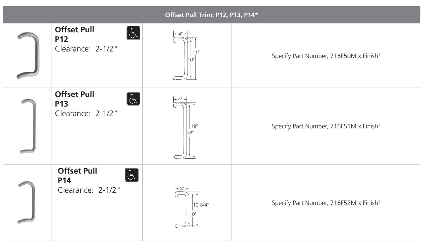
1. Available in 605, 606, 612, 613, 626, 629 and 630 finishes.
* Available on 1-3/4" thick doors only.

Trims and Functions
ED4000 Series
| Function | How to Order Example: | |||||||
|---|---|---|---|---|---|---|---|---|
|
Lever Designs
(Choose from list below) |
Dummy
ANSI No. 02 Function #850 |
Classroom
ANSI No. 08 Function #855 |
Nightlatch
ANSI No. 03 Function #859 |
|||||
| Muséo® | ||||||||
| Georgia | ||||||||
| 102 | 103 | 1044 | 124 2 | 125 2 | ||||
| Salvador | ||||||||
| 106 | 107 | 108 | 109 | 110 | 123 2 | 128² | ||
| Marc | - | 2 | ||||||
| 1114 | 1124 | 1144 | 115 4 | 1164 | 1302,4 | 1312,4 | 132 2,4 | |
| Jackson | ||||||||
| 1054 | 1174 | 119 4 | 1214 | 1224 | 126 2,4 | 127 2,4 | ||
| Piet* | ||||||||
| 21G | 21L | 21M | 215 | 23M | 25M | 27M | ||
| Joseph 3 | ||||||||
| 133 | 134² | 135 | 136 | 137 2 | 138² | |||
| Georges | ||||||||
| 139 | 140 | 141 | 142 | 143 | ||||
| Laszlo | 2 | |||||||
| 147 | 148 2 | 149 | 150 | |||||
ED4000.18
* See pages 36 for how to order the Muséo® Piet Lever Collection. 1. Classroom function trims can be converted to Storeroom function by a simple field adjustment. 2. Complies with codes requiring lever to return to within 1/2" (13mm) of door face.
3. 135-138 contain white or back polycarbonate insert 4. Not available in 32D or 32 finish

ED4000 Series
Electrified Exit Devices
The Corbin Russwin ED4000 series electrified exit devices offer a complete range of options that may be integrated into the monitoring security and alarm systems of most buildings. The continuum of appearance is maintained, as well as the security and function of the ED4000 series mechanical exit device.
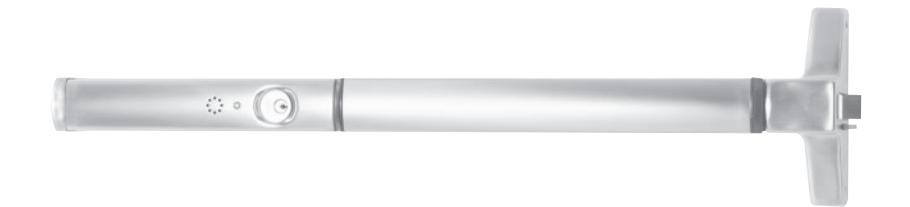
| List No. | Exit Device Description | Available Options | ||||||
|---|---|---|---|---|---|---|---|---|
| M61 | M91 | M92 | M93 | M97 | D | MELR | ||
| ED4200 | Rim Exit Device | x | x | x | x | x | x | x |
| ED4200S | Rim SecureBolt® Device | x | x | x | x | x | x | x |
| ED4400 | Surface Vertical Rod | x | x | x | x | x | x | x |
| ED4800 | Concealed Vertical Rod | x | x | x | x | x | x | x |
Electrified Hardware Option Descriptions
| M61 | Alarm Option |
|---|---|
| M91 | Bolt Monitor |
| M92 | Touchbar Monitor |
| M93 | Trim Monitor |
| M97 | Electric Dogging |
| D | Delayed Egress |
| MELR | Motorized Electric Latch Retraction |
* Add as suffix to exit device. Example: ED5400D x 630 x RHR
Notes:
1. The following options cannot be ordered together on the same device:
| D x M52 | M52 x M61 |
|---|---|
| D x M61 | M52 x M97 |
| D x M92 | M61 x M92 |
| D x M97 | ED4400 x M61 with Monitors M91, M92 or M93 |
D x MELR MELR x M97 D x MELR MELR x M61
2. When ordering a Surface Vertical Rod exit device with the D option (ED4400D), rod and latch quards (provided by others) must be used.

ED4000 Series
Electric Latch Retraction - MELR
The Motorized Electric Latch Retraction (MELR) exit device provides remotecontrolled latch retraction that delivers quiet, smooth operation for convenient, hassle-free egress. Easily installed in new applications and available as retrofit rail kit assemblies for field updates, the MELR features maintenance-free design with few moving parts using 86% less power consumption during retraction than solenoid devices. Plus, MELR is powered by a standard power supply, simplifying installation and increasing system design flexibility.
Application
SecureBolt® Exit Devices Rim Exit Devices Surface Vertical Rod Exit Devices Concealed Vertical Rod Exit Devices Mortise Exit Devices
Listings
UL listed for both Panic and Fire Exit Hardware.
Bar Length
Easily field cut to size.
Standard: 36" (914mm)* bar fits 34"- 36" (762mm-914mm) door.
*Bar fits 34"-36" when equipped with MELR Option.
Optional: 48" (1219mm)* bar fits 36"-48" (914mm-1219mm) door; specify W048.
*bar fits 39"-48" when equipped with MELR Option
Electrical Specifications
24VDC (BPS-24-1) regulated/filtered power supply. Requires 1A per device
Motor Driven Latch Retraction
.65 amp max during retraction .2 amp holding-continuous duty
Device bolts remain retracted for as long as the device is energized.
Removal of power returns the device to the life safety, self-latching mechanical mode.
Interface with central or local fire alarm system, automatic door operators, access control systems, security alarm systems, and blow open door systems.
Amount of rail retraction is automatically controlled by controller PC board; system actively monitors position and speed and adjusts itself.
Timer
Digital retraction timer (0-20 seconds) or set to power mode for access control systems.
Hinges
Standard electric hinge. No special power transfer required.
Note: This feature is not available with Electric Dogging (M97) or delayed egress (D) on the same device.
Warranty
5 years
How to Order
Specify Quick Code MELR.


MELR Retrofit Device Assembly
ED4000 Series
Existing solenoid and mechanical exit devices can be retrofit to motorized electric latch retraction (MELR) by purchasing retrofit kits via the following associated part numbers.
| List Number | Product Description | Available Options | |||
|---|---|---|---|---|---|
| None | M93 | M107 | M107 & M93 | ||
| CRMELR-36 | ED5000 36" MELR DEVICE ASSY | X | X | X | X |
| CRMELR-48 | ED5000 48" MELR DEVICE ASSY | X | X | X | X |
Note:
- For devices that use the M91 option, simply connect the wire from the existing switch to the new rail.
- For devices that use the M92 option, the existing switch needs to be moved and wired to the new rail.
- For a list of replacement parts for existing motorized electric latch retraction devices, contact Technical Product Support at 888-607-5703.
- 782 Controller CANNOT be used with MELR. Recommend BPS-24-xx
Latchhead Assemblies Requirements
The MELR retrofit device assemblies can only be added to ED4000 Series exit devices manufactured after April 2015.
Latchhead Pins (Beginning April 2015 (17/15))
Latch Head Pins (Prior to April 2015 (17/15))
Devices with short pins can NOT be upgraded. New latch head must be ordered for upgrade to MELR.
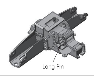
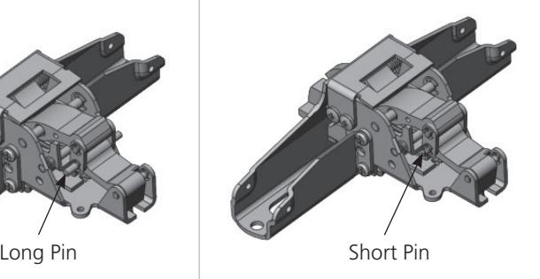
Note: Label with date code is located on front face of latch head.

ED4000 Series
Electric Dogging - M97
This electronic feature will provide continuous dogging when power is applied and the push bar is depressed manually. Interruption or removal of the power will release the pushbar and return the exit device back to normal operation.
Application
SecureBolt® Exit Devices Rim Exit Devices Surface Vertical Rod Exit Devices Concealed Vertical Rod Exit Devices
Listings
UL listed for Panic Exit Hardware.
Electrical Specifications
.35 Amps @ 24VDC-28VDC continuous duty (2) 36 volt holding magnets holding force (86 lbf. total)
Note: This feature is not available with latch pullback (MELR), delayed egress (D) or cylinder dogging (M52) on the same device.
Ordering
Specify quick code M97.
ED4000 Series
Delayed Egress Exit Device - D
The delayed egress option provides additional security and safety in a strong line of panic hardware. The delayed egress exit device is an electromechanical device used to secure interior or exterior openings. The option is available for rim, SecureBolt® and concealed vertical rod devices in all standard finishes.
Operation
The exit door is normally closed and latched. The Delayed Egress Exit Device "D" secures the door in the locked mode with the solid Red LED indicating locked mode status. Depressing the push pad for less than 3 seconds will sound the nuisance beep without initiating the alarm. Depressing the pushpad for 3 seconds or longer will initiate an irreversible local audible beeping tone and a visual amber indicator until the device releases. The person depressing the exit bar is denied egress for 15 or 30 seconds and security personnel are alerted. After the delay time of 15 or 30 seconds the device releases, the LED changes to Green, and the alarm changes to a steady tone which continues to alarm until manually reset by key. The remote monitoring contact outputs can be used to alert security personnel.
Note: The 15-second time delay is standard. 30-second time delay is optional (may be accepted by local jurisdiction).
Applications
- For use on hollow metal interior or exterior doors.
- Complies with NFPA 101 "Code For Safety To Life From Buildings And Structures" by National Fire Protection Association.
- BOCA options available to comply with National Building Code requirements. BOCA option is not suitable for installations in accordance with NFPA 101.
- 1-3/4" door thickness standard; 2" and 2-1/4" optional; specify D200 or D214 when ordering.
- Standard 36" device fits 36" doors only. Device cannot be cut less than 36".
- Option W048 fits doors 41" 48". Devices cannot be cut less than 41".
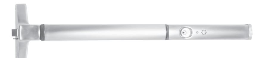
Listing
- UL/cUL Listed
- Controlled Exit Panic Devices (FULA/FULA7)
- Special Locking Arrangements (FWAX/FWAX7)
- BHMA (ANSI A156.3 and ANSI A156.24) Directory of Certified Exit Devices
Specifications
Input Voltage: 24VDC (+/- 10%) Regulated and filtered.
Power Consumption
• Standard Device: 500 mA
Standard Features Key Switch Operation:
- Normal: The system is armed by applying power to the device (solid Red LED). Depressing the pushpad for more than the nuisance delay time starts the exit delay cycle.
- Bypass: Turning the key switch clockwise to the bypass position allows immediate egress without alarming. The bar functions as a standard exit device. (Red LED flashes slow.)
- Reset/Delay: Used to reset device after the factory set 15 or optional 30-second delay cycle has timed out. If the device is armed, turning the key switch counterclockwise to the reset mode will release the device without alarm for egress and will rearm after 5, 10 (default), 20 or 40 seconds. (Red LED flashes quickly.)
Local Visual Status Indicator:
- RED: The exit device is secure and the delayed egress circuitry is energized.
- AMBER: The egress cycle has started, indicated by an irreversible local audible beeping tone.
- GREEN: Exit device is in alarm and has released.
Nuisance Delay Time:
With 3 second (default) setting depressing the push bar for less than 3 seconds sounds an audible beep without activating the irreversible alarm sequence. (Nuisance
Delay Times are dip switch selectable to Immediate, 1, 2, or 3 (default) seconds on the control board).
Internal Alarm Siren:
When the exit device is armed, depressing the push pad initiates the internal 85db alarm siren.
Door Position Switch (DPS) Control Board input: Allows external DPS wiring to control board for higher security. Alarm sounds when the DPS contacts open when the door is forced open.
Remote Control Inputs:
- Remote Reset: Accepts a momentary contact (keyswitch, pushbutton, etc.) to reset the unit during alarm or allows momentary egress selectable 5, 10 (default), 20 or 40 seconds when the unit is armed.
- Remote Bypass: Accepts a momentary contact to put the unit in a maintained bypass operation. The exit device functions as a standard device.
Alarm Outputs:
Contacts change only during alarm status. Alarm Relay Output contacts change state when device delay cycle has started (Alarm). Contacts are selectable for Normally Open (N.O.) or Normally Closed (N.C.) using the 2-pin jumper on the control board. N.O. is default setting. One set of contacts changes when device has released (Secure). Secure Relay Output has two sets of contacts (N.O. and N.C.). The Alarm Relay and Secure Relay contacts are SPDT type, rated 1A @24VDC.
Rearm After Closing (RAC):
Works in conjunction with an external DPS wired to the Control Board. Field Selectable Settings:
Setting 1: If the door is open beyond the momentary egress or remote reset time the device will Alarm.
Setting 2: If the door is open beyond the momentary egress or remote reset time the device will remain in egress mode indefinitely until the door closes (will not Alarm).
Copyright © 2001-2023, ASSA ABLOY Access and Egress Hardware Group, Inc. All rights reserved. Reproduction in whole or in part without the express written permission of ASSA ABLOY Access and Egress Hardware Group, Inc. is prohibited. Patent pending and/or patent www.assaabloydss.com/patents.
ED4000 Series
Door Sign:
Door sign per code included.
Note: This feature is not available with,
M52 Cylinder Dogging M61 Alarm Option M92 Touchbar Monitor M97 Electric Dogging
MELR Motorized Electric Latch
Retraction
How to Order
Specify "D" suffix after device. Example: ED4200SD
Delayed Egress Options Bolt Position Monitor M91:
SPDT (Single Pole Double Throw) switch that monitors the position of the latchbolt or vertical rods. To order, specify M91.
Outside Trim Monitor M93:
Used when outside trim is desired to be used with an external door position switch (by others) input. This switch will allow Bypass (disarms device) when the trim is used for ingress. The device requires setting after entry by means of the keyswitch on the device or a remote switch. To order, specify M93.
Note: If an external DPS is not used, standard trim will allow entry without affecting the device in an armed mode. The device will only be affected when the touchbar is depressed.
NFPA 101 Requirements: 30 Second Delay M88
Upon depressing the pushpad for 3 seconds or longer, the device will sound an audible beeping tone and allow the door to be opened after 30 seconds. The tone will then change to a continuous alarm until reset. Resetting of the alarm and re-arming of the device is accomplished by manual means only.
To order, specify M88.
Note: Where approved by the authority having jurisdiction, a delay not exceeding 30 seconds shall be permitted.
BOCA Requirements: BOCA 15 Second Delay M89 BOCA 30 Second Delay M90
Upon depressing the pushpad for 1 second or longer, the device will sound an audible beeping tone and allow the door to be opened within 15 (or 30) seconds. The tone will then change to a continuous alarm until rest. Resetting of the alarm and re-arming of the device occurs automatically once the door has been returned to the closed position for 30 seconds. The 30-second re-arming timer will re-start if the pushpad is depressed or the door is re-opened before actual re-arming of the device occurs. A DPS (Door Position Switch) is required for the BOCA option. To order, specify M89 (BOCA 15 second) or M90 (BOCA 30 second).
Note: BOCA option is not suitable for installations in accordance with NFPA 101.
Required Accessories Power Supply:
A regulated and filtered power supply with a Fire Alarm interface is required.
1 Amp minimum @ 24VDC per device. Special options will require more amperage. Consult factory.
To order, specify:
- BPS-24-1 (1 AMP)
- BPS-24-2 (2 AMP)
- BPS-24-4 (4 AMP)
Power Transfer:
Allows the power to make the transition from frame to door without pinching or removal of insulation. Optional power transfer: EPTL – concealed transfer for up to and over 120° swing doors. To order specify Part No. 704F28. Consult catalog for additional recommended power supplies and accessories.
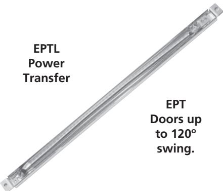
Refer to McKinney Power Transfer Device catalog for ElectroLynx options
|
ElectroLynx® Power
Transfer Device Options |
||||
|---|---|---|---|---|
| Hinge | External DPS | Options | ||
| QC8 | Not required | None | ||
| QC12 | Required | M91 or M93 | ||
Trims
See Trims and Functions, pages 14-15.
Cylinders
Utilizes a 1-1/8" mortise cylinder with an A02 cam. Cylinder not included unless specified. See Quick Codes, page 34.
Warranty
Exit devices carry a five-year limited warranty. Electronic components carry a two-year limited warranty. Trim carries a one-year limited warranty.

ED4000 Series
M61 Option and ED40AK Alarm Kit
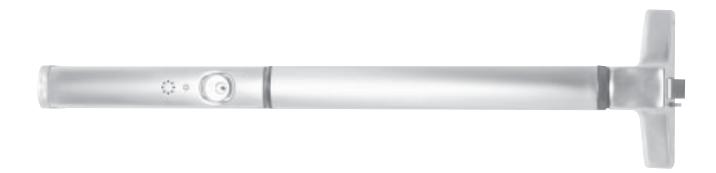
Activation
Alarm is armed by turning key clockwise. Low audible chirp indicates alarm has been activated. 20-second delay allows egress before alarm is set (selectable, 7, 10, 15 and 20) Alarm will sound when the exit device pushpad is depressed.
Continuous Alarm Mode
Alarm sounds continuously when the exit device pushpad is depressed. Alarm must be manually reset by keyswitch. Dip switch setting allows auto reset from 2, 5 or 10 minutes. LED flashes after device has reset.
Low Battery Warning
Audible chirp every 30 seconds.
Warning Decal
"EMERGENCY EXIT–ALARM WILL SOUND" provided.
REX and Passage Delay
A 7, 10, 15 or 20-second delay (after arming) permits egress (by turning key clockwise).
Alarm Shunt
Shunt alarm input for devices with signal, outside trim monitors (M91 & M93)or card access.
Power Requirements
One 9-volt battery (included).
Alarm Strength
105db @ 10 feet.
Arm/Disarm
Requires one 1-1/8" mortise cylinder with an A02 cam. Clockwise turn arms the alarm, counterclockwise turn disarms or silences the alarm. Low audible chirp indicates alarm has been activated.
Device Status
A Red LED indicator will illuminate every 30 seconds when the alarm is armed. DIP switch allows LED to be changed to green if desired.
Tamper Resistant
Built-in safety monitor sounds alarm when tampering occurs.
Cylinders
Cylinder not included unless specified. See How to Order, page 38.
Door Width
Available for 36"-48" devices only. Not available with devices less than 36". 48" device can be cut to fit 42" door.
Quick Code
M61
Kit
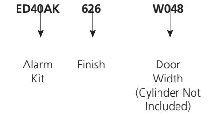
Available in kit form for field retrofit. Order ED40AK.
Hard Wired Option
A hard wired option is available by using a 9VDC output power supply and a remote power harness. Specify 784 to order the 9VDC output power supply. See page 28 for 784 power supply information. Specify 709F989 to order the remote power harness for a 36" device and specify
709F999 to order the remote power harness for a 48" device.
Exceptions
Dogging not available with M61 option and ED40AK alarm kit. The ED40AK for the ED4000 series exit devices cannot be retrofitted in the field to ED4400 series surface vertical rod exit devices.
The alarm option is available for the surface vertical rod devices by factory order only. To order, add the quick code
suffix M61 to the device number; for example, ED4400 x M61.
Please note, in accordance with Corbin Russwin's standard limited warranty, any attempt to retrofit the ED40AK to a surface vertical rod exit device will void the warranties for these products.
Surface vertical rod exit devices with M61 alarm option cannot be ordered with M91, M92 or M93 monitors.
M61 alarm option is not available with delayed egress (D).
How to Order
Ordering example for Exit Device
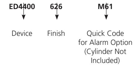
Ordering Example for Alarm Kit Only
Copyright © 2001-2023, ASSA ABLOY Access and Egress Hardware Group, Inc. All rights reserved. Reproduction in whole or in part without the express written permission of ASSA ABLOY Access and Egress Hardware Group, Inc. is prohibited. Patent pending and/or patent www.assaabloydss.com/patents.

ED4000 Series
BPS-24-2 Power Supply
Provides 2 Amps of output current at 24VDC and can control a total of 5 Electric Dogging Devices. A separate switching device (key switch or push button) must be used to control the locking device.
Specifications
- 120VAC Input Power
- 24VDC @ 2 Amp Output
- Fire Alarm Interface
BPS-24-4 Power Supply
Provides 4 Amps of output current at 24VDC and can control a total of 10 Electric Dogging Devices. A separate switching device (keyswitch or push button) must be used to control the locking device.
Specifications
- 120VAC Input Power
- 24VDC @ 4 Amp Output
- Fire Alarm Interface
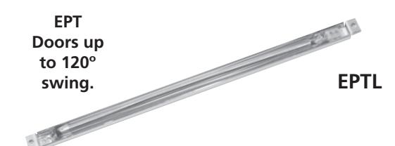
EPTL
Concealed power transfer for over 120° swing doors. Installs in door and frame edges. Supports wires up to .25" (6mm) thick, and works with doors hung with butt hinges, continuous hinges and pivots. To order, specify Part No. 704F288.

Electrified Options & Accessories
ED4000 Series
Monitors - M91, M92, M93
Operation
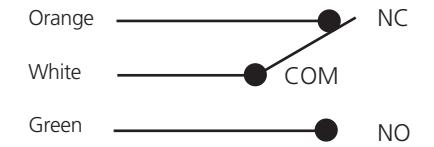
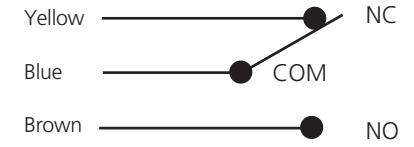
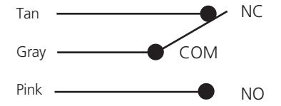
Monitors are used to indicate the authorized and unauthorized use of an opening or to signal and control other opening hardware, such as magnetic locks. Each monitoring device is equipped with one internal single-pole double-throw (SPDT) switch per monitor.
Bolt Position Monitoring - M91
Provides indication of the position of the deadlatch or vertical rods. Used with security systems to monitor the deadlatch in rim, SecureBolt® devices and rods in CVR & SVR devices.
Application
See chart on page 19.
Listings
UL listed for Panic Exit Hardware.
Electrical Specifications
2 Amps @ 28VDC SPDT contacts.
Ordering
Specify quick code M91.
Touchbar Monitoring - M92
Provides indication of the pushpad being depressed. Used as a request to exit to shunt alarm systems, release electromagnetic locks or monitor egress.
Application
See chart on page 19.
Listings
UL listed for Panic Exit Hardware.
Electrical Specifications
2 Amps @ 28 VDC SPDT contacts.
Ordering
Specify quick code M92.
Outside Monitoring or Signaling - M93
Provides indication of the device being operated from the outside. Used as a request to enter signal switch to shunt alarms; also used to monitor entry.
Application
See chart on page 19.
Listings
UL listed for Panic Exit Hardware.
Electrical Specifications
2 Amps @ 28VDC SPDT contacts.
Ordering
Specify quick code M93.
Electrified Options & Accessories
ED4000 Series
BPS Power Supply Operation
Power supplies are designed to provide reliable filtered and regulated power for long life to a variety of electrified hardware components. All modular power supplies are designed to meet UL 1481 Standards. Recommended for the M97 and delayed egress exit devices.
Features
- Fire panel emergency release input
- PC Board mounted system LED indicator
- Regulated and filtered with input and output protection
- Battery charging is provided from a separate output terminal
Electrical Specifications
- Inputs: 115VAC @600mA
- Outputs: 12/24 VDC @ 1 Amp, 1.5 Amp or 4 Amp, Filtered and regulated output
Listings
- UL & cUL listed 1012 General Purpose Power Supply
- Fire & Burglar Alarm Power Supply Unit URT2
- Releasing device Accessory SYSW
- Access Control Systems Units ALVY
- Burglar Alarm Systems Power Supply APHY
Applications
- D Delayed Egress
- M97 Electric Dogging
Note: Batteries are not included with the BPS power supply.
784 Power Supply
Features
- Provides a fi ltered and regulated 9 VDC remote power
- Requires raceway through the door*
Includes:
- Plug-In Wall Transformer with approximately12' (3.6m) of shielded wire that provides input power to the power supply
- Includes 12' (3.6m) of shielded wire for connection between power transfer and power supply
- To order separately, specify 793F039
- *Recommended for new opening. Retrofi t application may require surface mounted wire mold and transfer loop by others.
| Model | Enclosure | Input | Output |
|---|---|---|---|
| BPS-24-1 | 12" (304mm) x 9" (229mm) x 4" (102mm) | 115VAC, 50/60 Hz. | 1.0 Amp @ 24 VDC |
| BPS-24-2 | 14" (356mm) x 14" (356mm) x 4" (102mm) | 115VAC, 50/60 Hz. | 2.0 Amp @ 24 VDC |
| BPS-24-4 | 15" (381mm) x 18" (457mm) x 6" (152mm) | 115VAC, 50/60 Hz. | 4.0 Amp @ 24 VDC |
| BPS-12-1 | 12" (304mm) x 9" (229mm) x 4" (102mm) | 115VAC, 50/60 Hz. | 1 amp @ 12 VDC |
| BPS-12-3 | 14" (356mm) x 14" (356mm) x 4" (102mm) | 115VAC, 50/60 Hz. | 3 amp @ 12 VDC |
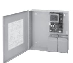
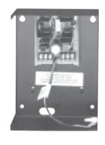
BPS Power Supply 784 Power Supply
Exit Controls and Switches
Key Switches
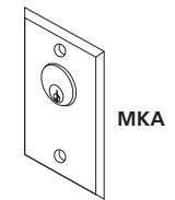
MKA - (1) SPDT Maintained MK - (1) SPDT Momentary MKN - (1) SPDT Momentary NS MK2 - (1) DPDT Momentary MKPZ x MKS - (1) SPDT Momentary with audio Double Gang x Additional Switch Note: All key switches come standard with 12/24 VDC bi-color LED.
Specifications
- Keyswitch for operation using a standard 1-1/8" mortise cylinder (A02 cam) (cylinder not included).
- Contact Rating 5 Amps @ 12-24VDC
- SPDT 3-position.
Push Buttons

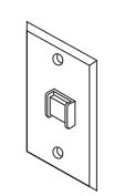
PB2 - (1) SPDT Momentary PB2 - (1) DPST Remote Momentary PB3 - (1) DPST Momentary PB3A - (1) DPST Maintained (Alt. Action) PB3EA - (1) DPST Alternate
Specifications
• 3 Amps @ 12-24 VDC
Audible/Visual Annunciators
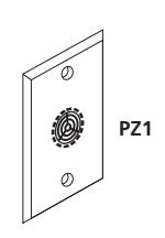
PZ1 - Sonalert 90db @ 2ft. 12-24VDC. Mounted on one gang stainless steel plate.
Digital Entry
DK-12 - Digital Keypad - 4 User DK-26SS - Digital Keypad NS - 59 User - SS Finish DK-26BK - Digital Keypad NS - 59 User -
Power Transfers
Black Finish
TSB B-C - Door Cord

Electrified Applications
ED4000 Series
Latch Pullback - MELR Option Components
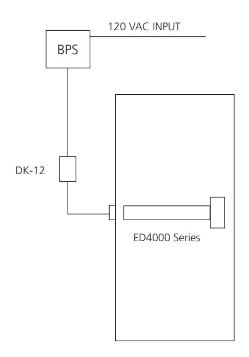
ED4000 Series x MELR Latch Retraction Exit Device - Corbin Russwin DK-12 – Digital Keypad Power Transfer Hinge
Operation
Operation of DK-12 Digital Keypad will allow keyless entry from the non-protected side of opening. Free exit using the exit device from the protected side of the door.
Electric Dogging & Touchbar Monitoring Switch - M97 & M92
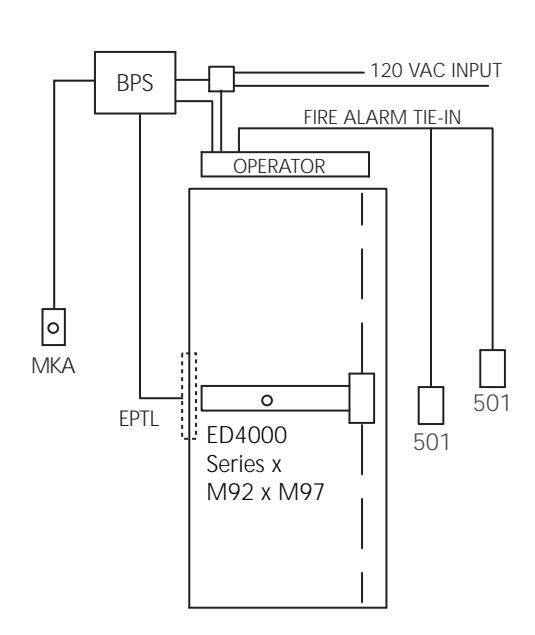
Components
ED4000 Series x M92 x M97 with Cyl. + Bar Monitor & Electric Dogging - Corbin Russwin Automatic Door Operator - Norton 501 Push Switch or 700 Wave to Open Switch - Norton Power Transfer Hinge BPS Power Supply - Corbin Russwin Key Switch - Corbin Russwin
Operation
Operation of Electric Dogging combined with the Door Monitor Switch will enable Push Switches for operation of the 6000. A maintained keyswitch will control the activation of the electric dogging which is powered by the Power supply. A Fire Alarm Tie-In, if required, will release the dogging and let the operator work in manual mode when activated. (NOTE: Electric Dogging is not automatic like Latch Pullback. It requires the bar to be pushed in manually the first time after applying power.)

Electrified Applications
ED4000 Series
Latch Pullback - MELR Option with Norton® Automatic Door Operator
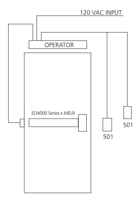
Components
ED4000 Series x MELR Latch Retraction Exit Device - Corbin Russwin Automatic Door Operator - Norton 501 Push Switch or 700 Wave to Open Switch - Norton Power Transfer Hinge Keyswitch - Corbin Russwin
Operation
Activation and operation of Push Switches from either side of door will be controlled by the Maintained Keyswitch. The Push Switches will in turn activate Latch Retraction Exit Device. An internal timer on the 6000 will coordinate and prevent the door from being opened before latch retraction takes place. Standard timers on the 6000 will also provide length of time door is open and latch being retracted. Door operator also acts like standard closer when opened manually. ED4000 Series x MELR
Exit Device with Electric Strike
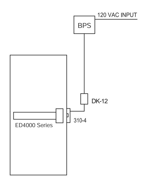
Components
ED4000 Series Exit Device – Corbin Russwin DK-12 – Digital Keypad 310-4 Electric Strike – Folger Adam® BPS Power Supply – Corbin Russwin
Operation
Operation of DK-12 Digital Keypad will allow keyless entry from the non-protected side of opening. Free exit using the exit device from the protected side of the door.

Electrified Applications
ED4000 Series
Exit Device with Delayed Egress Option on "Exit Only" Door
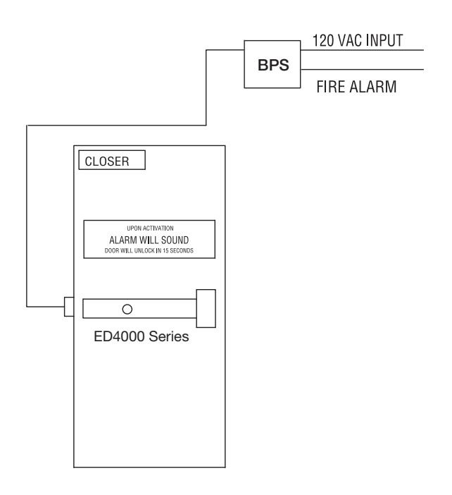
Components
ED4000 Series Delayed Egress Exit Device – Corbin Russwin Power Transfer Hinge BPS Power Supply – Corbin Russwin Surface Door Closer – Corbin Russwin
Operation
Operation of the ED4000 Series Exit Device will sound an alarm and activate either a 15- or 30-second alarm sequence inside of the exit device. After this time period, the device will release the pushbar, making it active, and egress is possible. When the fire alarm is activated, power to the exit device will be interrupted, allowing free egress and mechanical latching. Authorized alarm bypass and reset is done through the built-in keyswitch located in the exit device.
Exit Device - High Security Application M91, M92 and M93 Monitoring Switch Options With FAMSS-1C Door Position Switch
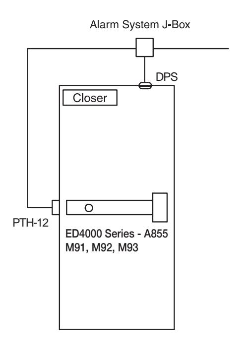
Components
ED4000 Series - A855 Nightlatch Trim – Corbin Russwin M91 Bolt Monitor Switch M92 Touchbar Monitor Switch M93 Trim Monitor Switch Door Position Switch Power Transfer Hinge
Surface Door Closer – Corbin Russwin
Operation
Operation of the ED4000 Series Exit Device with the M91, M92, M93 and a door position switch can be used together or individually to sound an alarm, shunt an alarm, monitor the door's security or as a "Request to Exit" in conjunction with a magnetic lock.

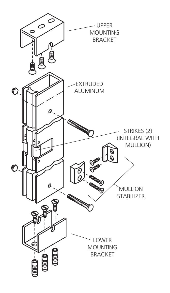
Mullions
ED4000 Series
CR808 Mullion
Used to install two Rim Exit Devices in a double door opening. May be quickly and easily removed when a full double door opening is temporarily required.
Materials and Finish
Extruded aluminum mullion,
1-1/4" x 3-1/2" x 8'2" (for 8'0" doors), supplied with two integral strikes, top and bottom mounting brackets, two sets of mullion stabilizers, and zinc-plated fasteners for metal frames and concrete fl oors. May be cut, drilled and tapped in the fi eld for Rim Exit Devices. Available in 628 and 695 fi nishes.
Ordering
To order, specify Part No. CR808* x Finish.
Mullion Stabilizer Kit
Controls the movement of the mullion. Recommended for openings over 7' high or whenever door movement must be minimized. Available in 628 and 695 fi nishes. Two sets supplied standard with all CR808 mullions. To order separately, specify Part No. 653F11-1 x Finish.

Options and Accessories
ED4000 Series
Shim Kits
Designed for mounting an exit device over raised vision light molding. Each kit contains two sets of 1/8" thick shims to shim a device 1/8" (3mm) or 1/4" (6mm). Black fi nish. To order with exit device, specify M58. To order separately, specify Part No.
| Exit Device Type | Shim Kit Part No. |
|---|---|
|
ED4200, ED4200S,
ED4800 |
697F35-8 |
| ED4400 | 697F36-8 |
Cylinder Dogging Kits
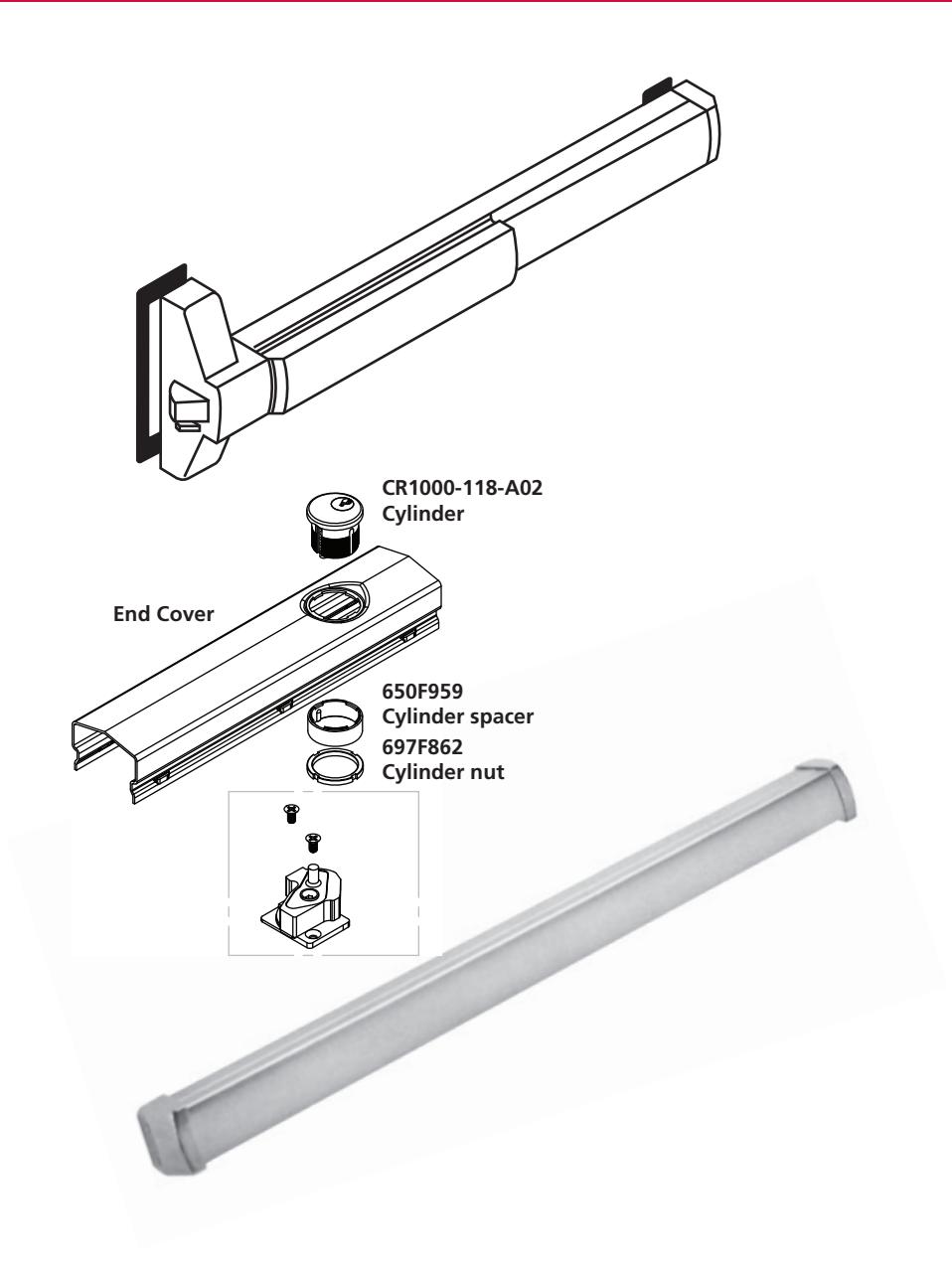
Designed to convert a panic device from hex key dogging to cylinder dogging. To order cylinder dogging kit, specify Part No. x Finish below. Cylinder not included.
| Bar Length |
Cylinder Dogging Kit
Part No. |
|---|---|
| Standard W036 | 653F13M x FIN |
| W048 | 865F14M x FIN |
ED5000DB Inactive Bar
Non-operating dummy pushbar available for doors up to 48" wide. May be fi eld cut for narrower doors. To order, specify ED5000DB x Finish.
Surface and Concealed Vertical Rod Extension Kits
Used to extend the height of standard length rods supplied with ED4400 and ED4800 Series exit devices. Available in 2", 6" and 12" sizes. To order with exit device, see How to Order, page 35. To order separately, specify Part No. x Finish.
| Rod Extension |
Rod Extension Kit
Part No. |
|---|---|
| 2" (50mm | 655F15 x Finish |
| 6" (152mm) | 655F16 x Finish |
| 12" (305mm) | 655F17 x Finish |
| 24" (610mm) | 684F42 x Finish |
Options and Accessories
ED4000 Series
Rim Strike (Screws Included)
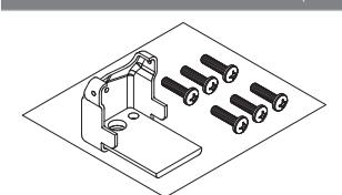
End Cap Reinforcement**
A solid steel plate, welded to the end bracket, evenly distributes impact forces over a larger surface area, eliminating point loading. To order with an exit device, specify M109. To order separately specify 705F09 x finish.
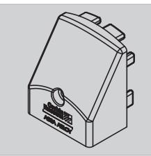
Flush End Cap
Durable heavy-duty cast steel or stainless steel, sits flush on the exit device rail and has a low profile which eliminates catch points. To order with a device, specify M110. To order separately specify 710F00M x finish.
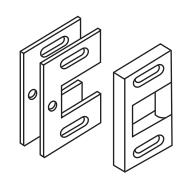
Rim Strike
Standard on ED4200 and ED4200S devices, Supplied with two 1/16" (2mm) shims. For doors with 1/2" (13mm) or 5/8" (16mm) stop. Adjustable to compensate for shrinkage and swelling of door. 3" x 2" (76mm x 51mm). Black finish only. To order separately, specify 650F31-8.


Top Strike
Standard on ED4400 and ED4800 devices. Supplied with two 1/16" (2mm) shims and one 1/16" (2mm) locking plate. Adjustable to compensate for shrinkage and swelling of door. 1-9/16" x 15/16" (40mm x 24mm). Black finish only. To order separately, specify 650F548.

Bottom Strike
Standard on ED4400 and ED4800 devices. 1-1/16" (27mm) diameter x 1/16" (2mm) lip x 11/16" (17mm) high. Black finish only.
Both top and bottom strikes are included in the vertical rod parts packet. To order parts packet, specify 650F57-8.
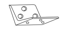
Flush Transom Top Strike Bracket
Optional for use with ED4400 devices. Used to mount top strike on openings with flush transom. 2-1/2" x 1-5/8" (64mm x 41mm). Black finish only. To order with exit device, specify M67. To order separately, specify 650F87-8.
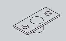
Bottom Strike for 1/2" Thresholds
Optional for use with ED4400 and ED4800 devices. Required for 1/2" (13mm) threshold or for flush mount. 2-5/8" x 1-1/16" (67mm x 27mm). Black finish only. To order with exit device, specify S09. To order separately, specify 650F88-8.
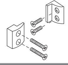
Mullion Stabilizer Kit
Controls the movement of the mullion. Two sets supplied standard with all CR808 mullions. Available in 628 and 695 fi nishes. To order separately, specify Part No. 653F11-1 x Finish.
Photoluminescent Touchpad Cover
The PathLite™ patent pending technology offers a number of benefits:
- Requires no wiring or maintenance
- Recharges with exposure to ambient light
- Unaffected by heat or cold
- Non-toxic, will not rub or fade
- Vandal resistant
**Note: Six 1/4 x 20 screws come standard with either M109 option or 705F09 kit. Only two screws required to fasten end cap assembly to door for retrofit. Other four screws are used with SecureBolt® Latch Head if ordered as an M109 option with complete device. When the kit is ordered a new end cap is also supplied.

Cylinders
ED4000 Series
Rim (Trim Only)
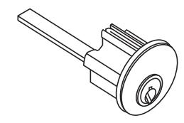
| Description | Part Number | Cylinder Ring | Part Number |
Cylinder Ring**
57 Function Only |
|---|---|---|---|---|
| 6-pin | CR3000-058 | 270F15 | CR3000-200N* | 270F15 |
| 7-pin | CR3000-058-7 | 654F07 | CR3000-200-7 | 654F07 |
| 6-pin, LFIC | CR3080-058 | 654F07 | CR3080-178 | 654F07 |
| 7-pin, LFIC | CR3080-058-7 | 654F08 | CR3080-178-7 | 654F08 |
| 6-pin, LFIC, less core | CR3070-058 | 654F07 | CR3070-178 | 654F07 |
| 7-pin, LFIC, less core | CR3070-058-7 | 654F08 | CR3070-178-7 | 654F08 |
| 6-pin, SFIC | CR3050-058 | 654F07 | CR3050-178 | 654F07 |
| 7-pin, SFIC | CR3050-058-7 | 654F08 | CR3050-178-7 | 654F08 |
| 6-pin, SFIC, less core | CR3040-058 | 654F07 | CR3040-178 | 654F07 |
| 7-pin, SFIC, less core | CR3040-058-7 | 654F08 | CR3040-178-7 | 654F08 |
| 6-pin, Security | CR3010-058 | 654F07 | CR3010-200 | 654F07 |
| 6-pin, Security IC | CR3090-058 | 654F07 | CR3090-178 | 654F07 |
| 7-pin, Pyramid | CR3020-058 | 654F07 | CR3020-200 | 654F07 |
| 7-pin, Pyramid IC | CR3030-058 | 654F07 | CR3030-178 | 654F07 |
* For K157, substitute -200
Mortise (Cylinder Dogging Only)
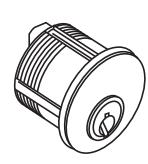
| Description | Part Number | Cylinder Ring |
|---|---|---|
| 6-pin | CR1000-118-A02 | N/A |
| 7-pin | CR1000-114-A02-7 | 270F15 |
| 6-pin, LFIC | CR1080-114-A02 | 270F15 |
| 7-pin, LFIC | CR1080-112-A02-7 | 654F07 |
| 6-pin, LFIC, less core | CR1070-114-A02 | 270F15 |
| 7-pin, LFIC, less core | CR1070-112-A02-7 | 654F07 |
| 6-pin, SFIC | CR1050-114-A02 | 270F15 |
| 7-pin, SFIC | CR1050-114-A02-7 | 654F07 |
| 6-pin, SFIC, less core | CR1040-114-A02 | 270F15 |
| 7-pin, SFIC, less core | CR1040-114-A02-7 | 654F07 |
| 6-pin, Security | CR1010-118-A02 | 270F15 |
| 6-pin, Security IC | CR1090-114-A02 | 270F15 |
| 7-pin, Pyramid | CR1020-114-A02 | 270F15 |
| 7-pin, Pyramid IC | CR1030-114-A02 | 270F15 |
** K157 uses the 270F15 cylinder ring

How to Order the Muséo® Piet Levers
ED4000 Series
Muséo® Piet Lever Collection Trim and Finish Options
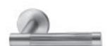
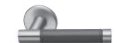
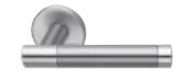
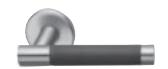
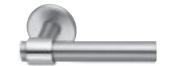
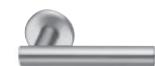
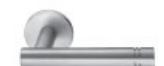
Grooved Insert 21G
Leather Insert 21L
Polished with Satin Insert 21M
Santoprene™ Insert 21S
With Raised Band 23M
Plain 25M
Plain with Two Grooves 27M
Piet Finish Codes
| BHMA/ASSA ABLOY Finish | Piet Code* | Description |
|---|---|---|
| 630 | 30 | Satin Stainless Steel |
| 629 | 29 | Bright Stainless Steel |
| 613E | 3E | Dark Oxidized Satin Bronze, Equivalent |
| BSP | BS | Black Suede Powder Coat |
| WSP | WS | White Suede Powder Coat |
| N/A | BK | Black (Santoprene™ or leather insert) |
| N/A | BN | Brown (leather insert) |
| N/A | 00 | No Insert |
* Code used to specify Piet Collection finishes only. Use available finishes list to specify desired finish when ordering.
Piet Lever Descriptions & Available Finishes
| Lever Designation | Lever Description | Available Finishes (as ordered) |
|---|---|---|
| 21G | Grooved Insert | 292929, 303030, 3E003E, BS00BS, WS00WS |
| 21L | Leather Insert | 29BK29, 29BN29, 30BK30, 30BN30, 3EBK3E, 3EBN3E, BSBKBS, BSBNBS, WSBKWS, WSBNWS |
| 21M | Metallic Insert | 293029** only |
| 215 | Santoprene Insert | 29BK29, 30BK30, 3E003E, BS00BS, WS00WS |
| 23M | Raised Band | 290029, 300030, 290030**, 3E003E, BS00BS, WS00WS |
| 25M | Plain | 290029, 300030, 3E003E, BS00BS, WS00WS |
| 27M | Two Grooves | 290029, 300030, 3E003E, BS00BS, WS00WS |
** Two-tone finish - grip of lever is 630, balance of lever is 629. Escutcheon finish will be 618.
Ordering Examples
Trim Only
| Quantity | Trim/Function | Lever Finish | Hand |
|---|---|---|---|
| 2 | 21M850 | 293029 | RHR |
In this example the escutcheon finish will be supplied in 618.
Exit Device with Trim
| Quantity | Exit Device | Trim/Function |
Lever
Finish |
Exit Bar
Finish |
Hand |
Cylinder
Option |
Door
Thickness |
Optional
Strike |
Door Width |
|---|---|---|---|---|---|---|---|---|---|
| 2 | ED4400M | 21G850 | 303030 | 630 | LHR | 6P | D200 | SB214 | W048 |

How to Order
ED4000 Series
Ordering Examples Exit Device Only
| Quantity |
Series/
Function |
Finish | Hand |
Misc.
Options |
|---|---|---|---|---|
| 24 | ED4200S | 626 | RHR | M51-M54 |
Removable Mullion
| Quantity | Mullion | Finish |
|---|---|---|
| 12 | CR808 | 695 |
Where to find ordering information and Quick Codes
| Trims and Functions | Page 14 |
|---|---|
| Removable Mullion | Page 29 |
| Handing | Page 34 |
| Door Thickness | Page 34 |
| Strike | Page 34 |
| Door Width | Page 34 |
| Door Height | Page 34 |
| Miscellaneous Options | Page 34 |
| Cylinder and Keying | Page 34 |
Exit Device with Trim
| Quantity | Exit Device |
Trim/
Function |
Finish | Hand | Door Thickness | Door Width | Door Height | Misc. Options |
|---|---|---|---|---|---|---|---|---|
| 36 | ED4400 | N855ET | 605 | LHR | D200 | W048 | H0706 | M51-M54 |
Trim Only
| Quantity |
Trim/
Function |
Finish | Hand | Door Thickness |
Cylinder
Option |
|---|---|---|---|---|---|
| 24 | N855ET | 625 | RHR | D214 | 6P |
Contract/Detailed Order – Exit Device with Trim
| Quantity | Exit Device |
Trim/
Function |
Finish | Hand | Door Height |
Optional
Strike |
Door Width | Misc. Options |
Cylinder/Key
Options |
Keyset |
|---|---|---|---|---|---|---|---|---|---|---|
| 36 | ED4400 | C855ET | 626 | LHR | H0800 | S09 | W048 | M52-M54 | 7P - VKC3 | AA1 |

Quick Codes
ED4000 Series
Cylinder and Keying
| Description | Specify |
|---|---|
| Less cylinder(s) | (standard) |
| Conventional 6-pin | 6P |
| Conventional 7-pin | 7P |
| LFIC | |
| LFIC 6-pin1 | C6 |
| LFIC 6-pin less core | CL6 |
| LFIC 6-pin with temporary construction core (Red) | CT6R |
| LFIC 6-pin with temporary construction core (Blue) | CT6B |
| LFIC 6-pin with temporary construction core (Green) | CT6G |
| LFIC 6-pin with temporary disposable core | CT6D |
| LFIC 7-pin | C7 |
| LFIC 7-pin less core | CL7 |
| LFIC 7-pin with temporary construction core (Red) | CT7R |
| LFIC 7-pin with temporary construction core (Blue) | CT7B |
| LFIC 7-pin with temporary construction core (Green) | CT7G |
| LFIC 7-pin with temporary disposable core | CT7D |
| SFIC | |
| SFIC 6-pin | C6S |
| SFIC 6-pin with temporary construction core (Blue) | CT6SB |
| SFIC 6-pin with Less Core | CLS6 |
| SFIC 6-pin with SFIC disposable temporary core | CT6SD |
| SFIC 7-pin | C7S |
| SFIC 7-pin with temporary construction core (Blue) | CT7SB |
| SFIC 7-pin with Less Core | CLS7 |
| SFIC 7-pin with SFIC disposable temporary core | CT7S |
| Security | |
| Security | HS |
| Security IC | CHS |
| Access 3® | |
| Access 3® - Patented | AP |
| Access 3® - Security | AS |
| Access 3® - High Security | AHS |
| Access 3® IC - Patented | ACP |
| Access 3® IC - Security | ACS |
| Access 3® IC- High Security | ACHS |
| Pyramid | |
| Pyramid Security fixed core | PS |
| Pyramid Security IC | PCS |
| Pyramid High Security fixed core | PHS |
| Pyramid High Security IC | PCHS |
| Pyramid IC with temporary construction core | CTP |
| Pyramid IC with temporary disposable core | CTPD |
| Pyramid IC less core | CLP |
| Keying and Keys | |
| 0-bitted with 2 blank keys | (standard) |
| Keyed random | KR |
| Construction master keyed | CMK |
* Not available with Rim or SVR lever trim - Classroom Function
Finish
| Description | Specify | |
|---|---|---|
| US3 | Bright Brass | 605 |
| US4 | Satin Brass | 606 |
| US9 | Bright Bronze | 611 |
| US10 | Satin Bronze | 612 |
| US10B | Dark Oxidized Satin Bronze, oil rubbed | 613 |
| US10BE | Dark Oxidized Satin Bronze Equivalent | 613E |
| US14 | Bright Nickel Plated | 618 |
| US15 | Satin Nickel Plated | 619 |
| US26 | Bright Chromium Plated | 625 |
| US26D | Satin Chromium Plated |
6261
(Trim only) |
|
Satin Chromium Plated
with MicroShield® |
626C2 | |
| US32 | Bright Stainless Steel | 629 |
| US32D | Stain Stainless Steel | 630 |
| Stain Stainless Steel with MicroShield® | 630C2 | |
| Satin Aluminum, Clear Anodized (mullions only) | 628 | |
| Dark Bronze Coated (mullions only) | 695 | |
| — | Black oxidized bronze,oil rubbed | 722 |
| — | Black Suede Powder Coat | BSP |
- 1. Contact factory for devices required in BHMA 626
- 2. Finish available with MicroShield® antimicrobial coating.
Lock/Cylinder Finish
| Lock | Cylinder/Core* |
|---|---|
| 605,606,611,612,613,613L,722 | 606 |
| 618,619,625,626,WSP | 626 |
| BSP | BSP |
* Finish when cylinder provided with lock
Door Height
| Specify |
|---|
| (standard) |
| H0702 |
| H0706 |
| H0800 |
| H0900 |
| H1000 |
| (standard) |
| H0802 |
| H0806 |
| H0900 |
| H1000 |
+ Not available with 55 function

Quick Codes
ED4000 Series
Door Width
| Door Width | Specify |
|---|---|
| 24" (610mm) | W024 |
| 36"(914mm) | (standard) |
| 48" (1219mm) | W048 |
Handing
| Hand | Specify |
|---|---|
| Right Hand Reverse | RHR |
| Left Hand Reverse | LHR |
Door Thickness
| Door | Specify |
|---|---|
| 1-3/4" (44mm) | (standard) |
| 2" (51mm) | D200 |
| 2-1/4" (57mm) | D214 |
Strike
| Description | Specify |
|---|---|
|
Surface and concealed vertical rod Bottom
strike for 1/2" thresholds |
S09 |
Removable Mullion
| Door Height | Specify |
|---|---|
| Up to 8'0" (ED4200 & ED4200S) | 808 |
Miscellaneous Options
| Description | Specify |
|---|---|
| Torx® head screws | M04 |
|
Knurling outside and inside (embossed touchbar -
device side) |
M201 |
| Knurling outside only (trim side) | M211,2 |
|
Knurling inside only (embossed touchbar -
device side) |
M221 |
| Abrasive coat outside and inside (trim and device) | M23 |
| Abrasive coat inside only (device side) | M24 |
| Abrasive coat outside only (trim side) | M25 |
|
24", 36" and 48" PathLite™ Photoluminescent Touchbar
Cover |
M49 |
| Less dogging | M51 |
| Cylinder dogging | M52 |
| Sex nuts and bolts (SNBs) | M54 |
| Shim kit (for vision light) | M58 |
| High Impact End Clamp | M109 |
| Flush End Cap | M110 |
1. All levers provided in a powder coat finish will be supplied with an abrasive coating
Electrical Options
| Description | Specify |
|---|---|
| Alarm Option | M61 |
| Bolt Position Monitor | M91 |
| Touchbar Monitor | M92 |
| Trim Monitor | M93 |
| Electric Dogging | M97 |
| Delayed Egress | D |
| Motorized Electric Latch Retraction | MELR |
2. Not available on museo and vineyard levers

Facts and Figures
ED4000 Series
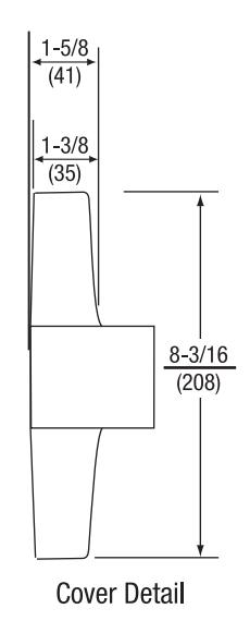
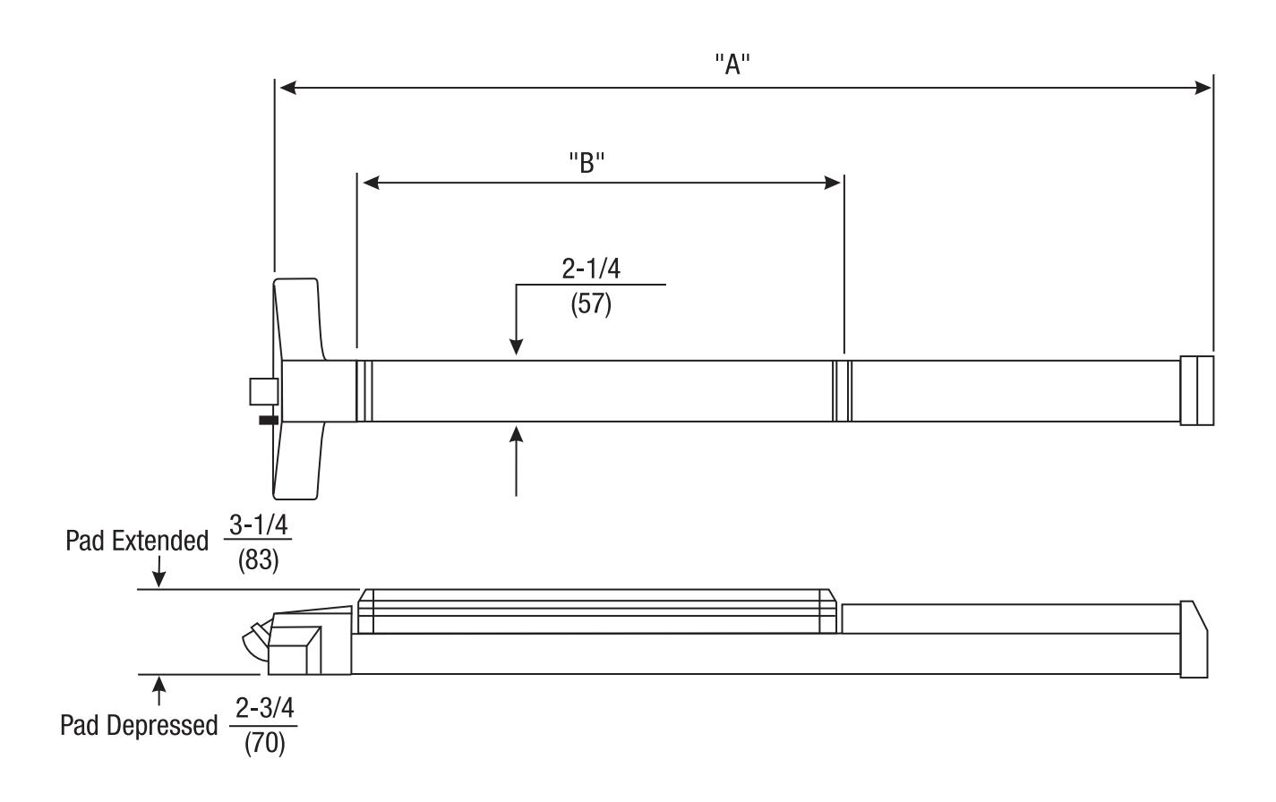
ED4000 Series (all variables)
| Series | "A" | "B" |
|---|---|---|
| ED4000 |
34-5/8"
(880mm) |
18"
(457mm) |
| ED4000 x W024 |
22-5/8"
(575mm) |
12"
(305mm) |
| ED4000 x W048 |
46-5/8"
(1184mm) |
24"
(610mm) |
Dimensions are shown in: inches mm

Helpful Terms
ED4000 Series
Abrasive Coat
Hard granular material applied to provide a non-slip tactile surface for the visually impaired.
Active Door
In a pair of doors, the door that is operable from the trim side.
Astragal
A vertical member applied to one or both sides of a pair of doors at the meeting edges. The astragal closes the gap between the two doors.
Coordinator
A device used on a pair of doors to ensure that the inactive door closes before the active door.
Deadlocking Latch
A supplemental latch that automatically deadlocks the latchbolt when pressure is applied to it.
Dogging
A mechanism that allows the latchbolt to remain retracted, permitting the door to operate as if it were a push-pull; it cannot be used on fire-rated exit devices.
Double Egress
A pair of doors of the same hand that swing in opposite directions, commonly found in corridors.
Dummy Trim
Trim only. Usually used on the inactive door of a pair of doors for design balance.
Exit Device (Panic Hardware)
A door locking device with a pushbar or crossbar which, when pressed, allows instant exit (egress).
Fire Exit Hardware
An exit device listed by an independent testing laboratory as meeting panic, fire and hose stream test standards; used on fire-rated openings.
Hand
The direction a door swings.
Inactive Door
In a pair of doors, the door that is inoperable from the trim side.
Latchbolt
A lock component that has a beveled end and projects into a strike, holding the door in a closed position.
Mullion
A fixed or removable vertical member that divides a door opening and provides a latch surface for a pair of rim exit devices.
Open Back Strike
For mortise exit devices, used on the inactive door (usually the vertical rod door) of a pair of doors that swing in the same direction. It permits the inactive door to open or close independently.
Reversible
Pertains to a product that may be changed in the field to accommodate any hand of the door.
Shim Kit
Pieces of metal that permit mounting of an exit device on a door that has a surface projecting vision light (glass bead) molding.
Split Astragal
An astragal that is split through the middle on a pair of doors, allowing both doors to operate independently.
Threshold
A strip fastened to the floor beneath a door. It serves as a stop, prevents heat loss, and provides a strike location for latching the bottom rod of a vertical rod exit device.
Trim
A knob, lever, pull, or thumbpiece used on the outside of an exit device door to control access to an area.
Universal Exit Device
An exit device that may be used on doors of either hand without any modifications.
Keying and Cylinder Terms Concealed Key Control (CKC)
The marking of standard key symbols on a cylinder in a location that is not visible once the cylinder is installed.
Construction Master Keying (CMK)
A cylinder preparation that allows temporary access by construction personnel.
Control key
A key used to remove and install interchangeable cores.
Cylinder
A lock component containing the combination that determines which keys will operate.
Security Cylinder
A cylinder which provides extra resistance to picking and unauthorized duplication of keys.
Interchangeable Core (IC)
A cylinder which can be removed and installed quickly with a control key by non-skilled personnel when rekeying is required.
Key Symbol
A letter/number combination in standard industry format (e.g., 1AA, AA1, etc.) which indicates exactly how a key or cylinder fits into a keying system.
Keyway
The opening in a cylinder plug through which the key enters.
Master Keying
Preparation of a cylinder to operate with keys of different levels of access.
Visual Key Control (VKC)
The marking of standard key symbols on keys and on the visible portion of the front of a cylinder.

Suggested Specification
ED4000 Series
Suggested Specification
Exit devices shall be ED4000 Series Narrow Stile Pushpad Exit Devices.
The exit device chassis shall be cold forged steel, electroplated for corrosion resistance, and shall be architecturally fi nished brass, bronze or stainless steel. The pushpad mechanism shall be constructed of extruded aluminum and shall be scalped with architecturally fi nished brass, bronze or stainless steel. The maximum projection shall be 3-1/4" when the pushpad is active and 2-3/4" when the pushpad is dogged down. Nylon bearings and stainless steel springs shall be used for long life and durability; only torsion springs are acceptable. Rear and active case covers shall be wrought brass or bronze and shall be plated to match the exit bar. Plastic or painted covers are not acceptable. Latchbolts shall be steel and shall incorporate a deadlocking latch feature for increased security. Devices without deadlocking latches are not acceptable. Mounting screws shall be concealed to deter tampering. Devices shall be closed on all sides with no pinch points. All exit devices shall be easily fi eld sized to accommodate various door widths.
Exit devices shall have single point, one quarter turn hex key dogging standard. Optional cylinder dogging shall be available. Devices with hex key dogging shall be easily fi eld converted to cylinder dogging. Panic listed devices shall be available less dogging. Trims shall be throughbolted with concealed fasteners. Escutcheon and pull type trims shall be constructed of brass or bronze. All lever trims shall use cast or forged levers. On trims with cylinders, the mechanism that locks and unlocks the trim shall be housed in the trim and not in the active case of the exit device. Lever trims shall match those on Corbin Russwin Mortise and Cylindrical Locksets.
Exit devices and trims shall be furnished in BHMA standard architectural fi nishes.
Exit devices shall be listed by Underwriters Laboratories (UL) for safety as panic hardware.
Certifi cation: ANSI/BHMA A156.3, Grade 1
Exit devices, trims and cylinders shall be from one manufacturer.
Trims and electronic components shall carry a two-year limited warranty.
Exit devices shall carry a fi ve-year limited warranty.

Notes
ED4000 Series

For additional information, contact your ASSA ABLOY Door Security Solutions sales consultant or visit www.corbinrusswin.com.
In U.S.
Corbin Russwin 225 Episcopal Road Berlin, CT 06037 Phone: 800-543-3658 Fax: 800-447-6714 corbinrusswin.com
In Canada
ASSA ABLOY Door Security Solutions Canada 160 Four Valley Drive Vaughan, Ontario Canada L4K 4T9 Phone: 800-461-3007 Fax: 800-461-8989 www.assaabloydss.ca
MicroShield®
As part of their promise to provide innovative solutions to their customers, certain ASSA ABLOY Group brands offer the MicroShield® technology, a silver-based antimicrobial coating designed to inhibit the growth of bacteria.
Microshield® is a registered trademark of ASSA ABLOY Access and Egress Hardware Group, Inc.

The Agion antimicrobial is not intended as a substitute for good hygiene. Coated products must
still be cleaned to ensure the surfaces will be free of destructive microbes. ASSA ABLOY makes no representations or warranties, express or implied, as to the efficacy of the Agion antimicrobial. A copy of the Agion warranty is available upon request. Agion is a registered trademark of Agion Technologies, Inc., Wakefield, MA, USA