Corbin Russwin Access 800 TWCI1 & TCPIP1 Series Trim by ED5000 Series Exit Device Installation Instructions_FM336
Open the original PDF document
View PDF

Corbin Russwin ASSA ABLOY
Installation Instructions For 9800 TWCl1 & TCPIP1 Series Trim by ED5000 Series with SecureBolt™ and Rim Exit Devices
FM336 10/18
Attention Installer
Please read these instructions carefully to prevent missing important steps.
Please Note: Improper installations may result in damage to the lock and void the factory warranty.
Important: The accuracy of the door preparation is critical for proper functioning and security of this lock.
Misalignment can cause premature wear and a lessening of security.
For installation assistance contact Corbin Russwin Inc., at 1-800-810-WIRE (9473)
Copyright © 2018 Corbin Russwin, Inc., an ASSA ABLOY Group company. All rights reserved. Reproduction in whole or in part without the express written permission of Corbin Russwin, Inc. is prohibited.
ASSA ABLOY, the global leader in door opening solutions
Table of Contents
| 1) Warning2 | |
|---|---|
| 2) General Description/Specifications/Features | 3 |
| 3) 9800 TWC1 Series Trim Product Illustration4 | |
| 4) Installation Instructions5 | |
| 5) Operational Check10 | |
| 6) Hard Wiring Options11 | |
| 7) PIP (PoE) Wiring Options12 |
1) Warning
Changes or modifications to this unit not expressly approved by ASSA ABLOY Inc. could void the user's authority to operate the equipment.
FCC:
NOTE: This equipment has been tested and found to comply with the limits for a Class B digital device, pursuant to Part 15 of the FCC Rules. These limits are designed to provide reasonable protection against harmful interference in a residential installation.
This equipment generates, uses, and can radiate radio frequency energy and, if not installed and used in accordance with the instructions, may cause harmful interference to radio communications. However, there is no guarantee that interference will not occur in a particular installation. If this equipment does cause harmful interference to radio or television reception, which can be determined by turning the equipment off and on, the user is encouraged to try to correct the interference by one or more of the following measures:
- Reorient or relocate the receiving antenna.
- Increase the separation between the equipment and receiver.
- Connect the equipment into an outlet on a circuit different from that to which the receiver is connected.
- Consult the dealer or an experienced radio/TV technician for help.
Industry Canada:
The term "IC:" before the radio certification number only signifies that Industry Canada technical specifications were met.
This Class B digital apparatus meets all requirements of the Canadian Interference Causing Equipment Regulations. Operation is subject to the following two conditions: (1) this device may not cause harmful interference, and (2) this device must accept any interference received, including interference that may cause undesired operation.
Cet appareillage numérique de la classe B répond à toutes les exigences de l'interférence canadienne causant desrèglements d'équipement. L'opération est sujette aux deux conditions suivantes: (1) ce dispositif peut ne pas causer l'interférence nocive, et (2) ce dispositif doit accepter n'importe quelle interférence reçue, y compris l'interférence qui peut causer l'opération peu désirée.

WARNING: To comply with "Fire Listed" doors, only alkaline batteries must be used.

2) General Description / Specifications / Features
The Corbin Russwin Access 800 TCWI1 Rim, SecureBolt™ Exit Device is designed for applications requiring wireless access control. The TCWI1 is a self-contained microprocessor-controlled access control product with non-volatile memory. It is able to utilize the existing wireless LAN 802.11 b/g in order to communicate with the access control system. The TCWI1 lock will hold a total of 2000 different user codes. This product is operated by six (6) "AA" alkaline batteries or by Corbin Russwin 784 9VDC power supply. Corbin Russwin Access 800 TCWI1 Rim, SecureBolt™ Exit Devices are designed with quality components to provide high security, performance and durability.
Using PoE technology coupled with approved third party software, this Access 800 TCWI1 Rim, SecureBolt™ Exit Device offers a complete, integrated access control system.
The TCWI1 Rim, SecureBolt™ Exit Device may be used for both indoor and exterior applications. A weather-protective gasket is recommended for exterior applications.
HID and iCLASS are registered trademarks of HID Global Corporation.
Items Supplied with Exit Device Items included with ED5 00 (S) (A) Rim or SecureBolt Exit Device by 9800 TCWI1 Series Trim
- Outside Escutcheon with keypad
- Outside motorized Trim Assembly
- Exit Device
- Rim cylinder for 9834
- Inside Escutcheon with Circuit board and battery Pack 6 "AA" alkaline batteries
- Screw Pack
Specifications
- Latch 1/2" standard
- 3/4" throw fire rated double doors
- (optional) M16- prefix
- Inside lever retracts latch
- Locks furnished for 1-3/4" to 2" doors
- U.L. Listed
- Deadlocking latch
- For 2-1/4" doors specify option D214
- Cylinder override
- Outside lever controlled by keypad, or key retracts latch
Features
- 2400 users per lock; 10,000 event audit trail
- Multiple time zone and holiday access scheduling
- Centralized lock management
- Real time door status monitoring
- First-In unlock configuration, either by time or by user (selectable)
- Lock down capable
- Input Power: PoE Class 2 Device, as defined by IEEE 802.3af
- Supports HID® 125 kHz prox or 13.56 MHz iCLASS® credentials (26 - 39 bit); supports CSN reads for other common 13.56 MHz cards, including MiFare, DesFire and Felica


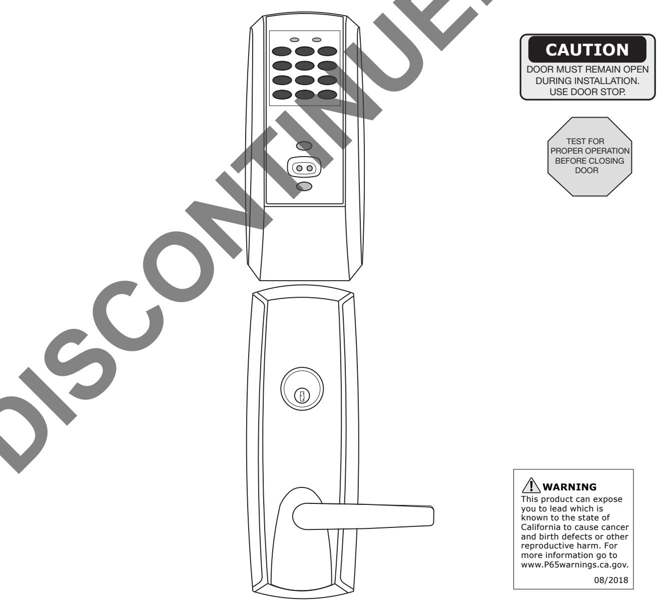
3) 9800 TCWI1 Series Trim Product Illustration
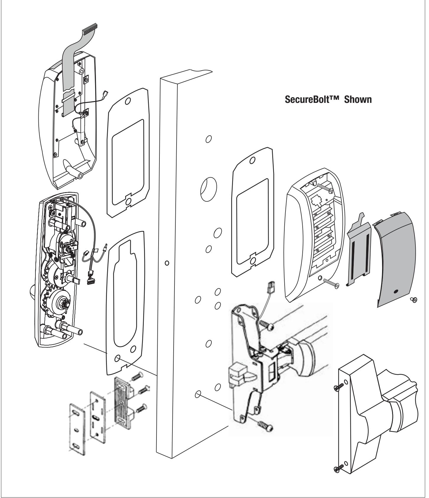

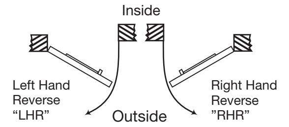
This device is not handed, however the Trim assembly is handed. Door should be fitted and hung. Verify box label for size of exit device, function and hand.
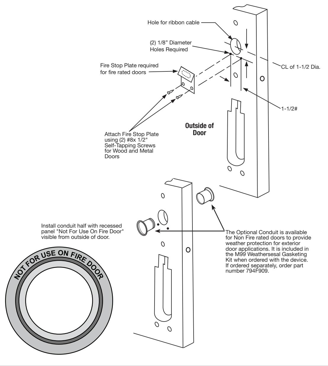
Prep door according to supplied Corbin Russwin Inc. door marker.


-
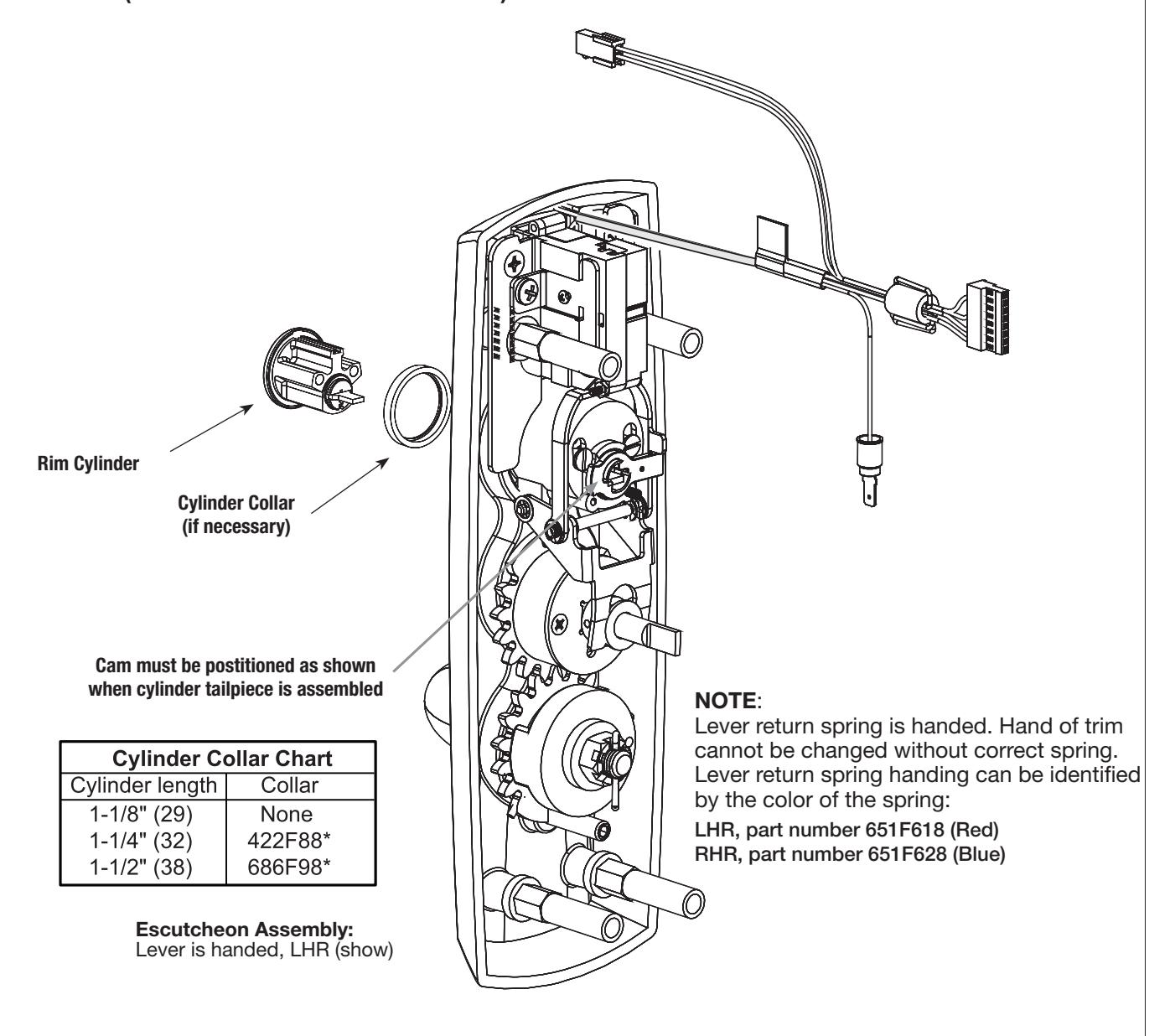
1. Check cylinder components.
- NOTE: Cylinders longer than 1-1/8" (29mm) will require collars. Refer to Cylinder Chart Below.
- 2. When required, cut cylinder tailpiece. Correct length is 1/16" to 3/16" (2 to 5 mm) beyond cylinder housing cam.
Assembly of cylinder:
- Insert cylinder housing prongs into matching notches of escutcheon.
- Pass cylinder tailpiece thru cylinder collar (when required) and slot cylinder housing cam.
- Fasten cylinder in escutcheon recess of collar using (2) mounting screws.
(DO NOT OVER TIGHTEN SCREWS.)

4) Installation Instructions
4
Outside Trim Assembly
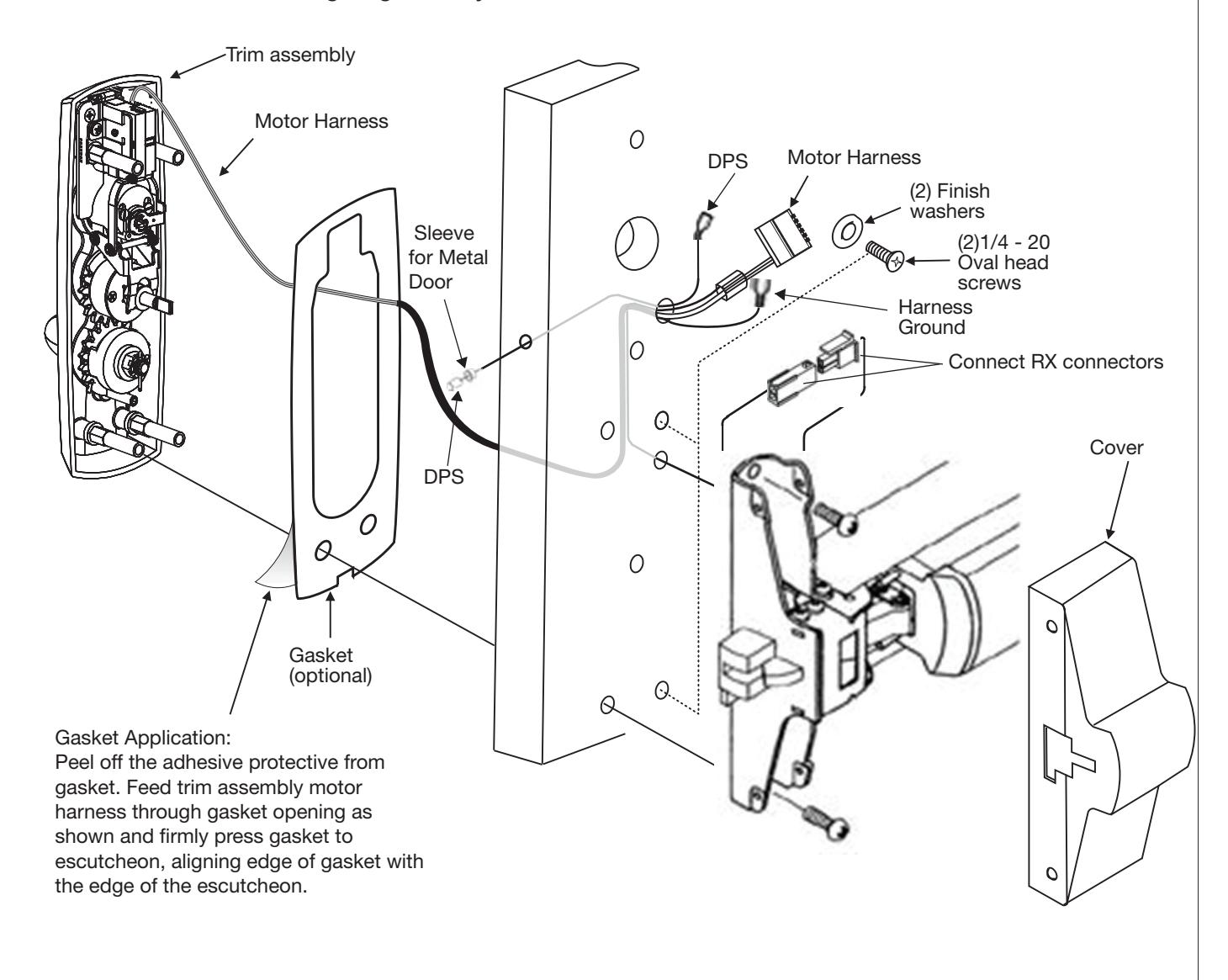
- 1. Route motor harness pigtail thru 3/4" diameter hole "C" on inside of door and out other side through trim assembly prep. Connect to trim assembly motor harness.
- 2. Route RX connector thru hole "C" on inside of door, thru race way between hole "C" and trim cutout, and through 1/2" diameter hole "D" back to inside of door. Connect to the RX connector from the device.
- 3. Mount trim assembly to door pulling slack wire from motor harness pigtail towards device side of door. Be careful not to pinch harness wires.
- 4. When mounting trim, lift tailpiece to pass through hole on device side. Ensure tailpiece is in vertical position.
- 5. Fasten trim assembly to door through holes "A" using (2) 1/4-20 oval head screws and two (2) finish washers. Finger tighten only!


5 Installation of Outside Keypad Escutcheon
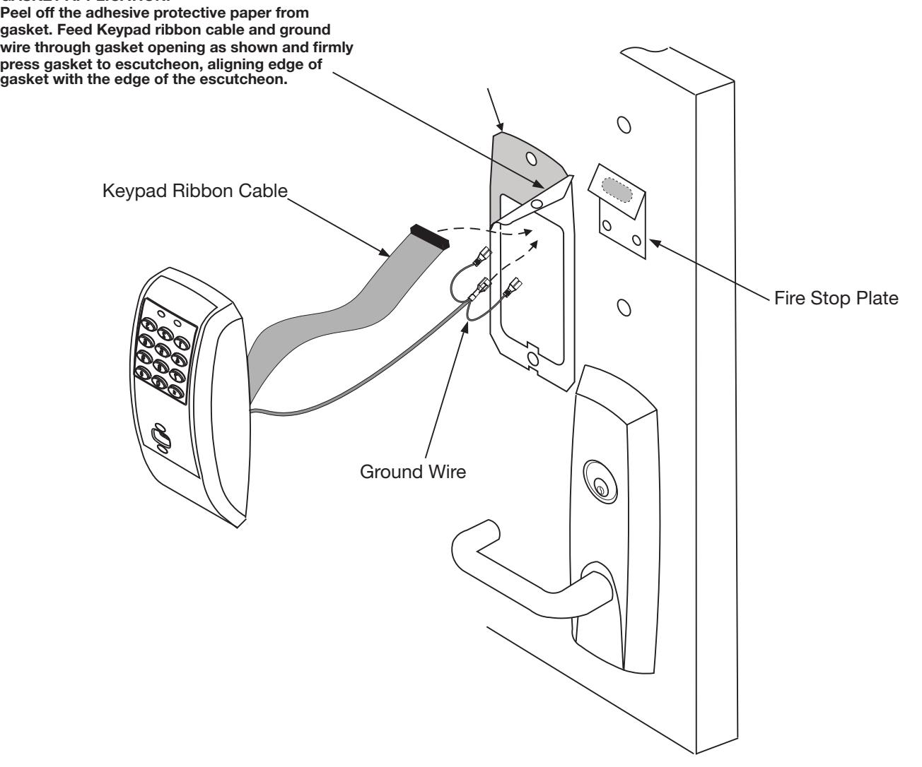
- 1a. For fire rated devices, feed keypad ribbon cable/connector and ground wire from outside of door through fire stop plate and hole in door.
- 1b. For non fire rated exit devices, feed keypad ribbon cable/connector and ground wire through hole in door.
- 2. Place escutcheon against door surface.
GASKET APPLICATION:


Battery Installation
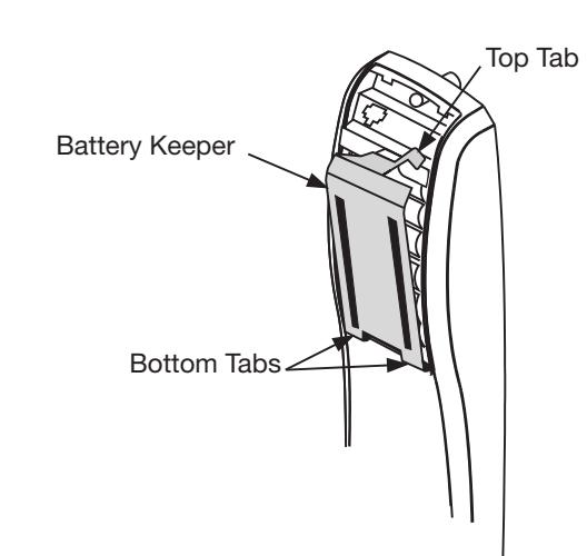
- 1. Remove battery keeper by lifting top tab and pulling away from the unit.
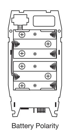
- 2. Install (6) AA Batteries into controller compartment being careful to align +/-polarity properly.
- 3. Install Battery Keeper by first inserting bottom tabs in bottom slots of controller. Lift the top tab over batteries and snap into position.
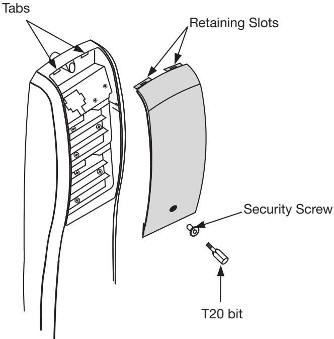
- 4. Attach battery cover to inside controller escutcheon making sure to line up tabs with retaining slots in battery cover. Secure with security screw using security T20 bit.


5) Operational Check
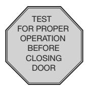
- 1. For exit devices without cylinder override trims, go to Step 3 below.
- 2. For Rim and Secure olt exit devices with 9834 Series cylinder override trims.
- a. Insert key into cylinder and rotate.
- b. While holding key in rotated position, operate outside lever to retract latch.
- c. They should rotate freely and outside lever should retract latch.
- 3. Depress exit device pushpad to retract latch.
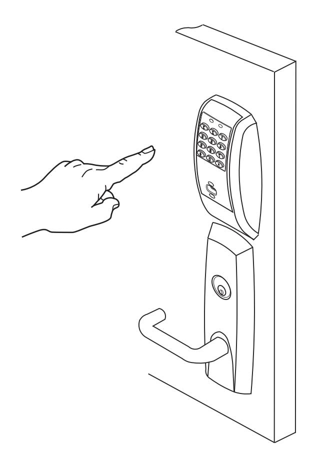
- 4. Use Proximity Card or Pin code set up with Lock Configuration Tool. This should unlock outside lever and allow latch to be retracted. Please see Network Lock Configuration Tool User Manual (WFMN1) for more information.

6) Hard Wiring Instructions
6.1 Important
- 1. Caution: Disconnect all input power before beginning installation to prevent electrical shock and equipment damage.
- 2. Installer must be a trained, experienced service person.
- 3. All wiring must comply with applicable local electrical codes, ordinances and regulations.
6.2 Installation Notes
- 1. With new applications, an ElectroLynx<sup>™</sup> door harness with 8 and 4 pin connectors will be pre-installed inside door by ASSA ABLOY door manufacturer when specified during ordering process.
- 2. Wiring to pigtail harness is per facility wiring requirement. ElectroLynx<sup>™</sup> connector terminations and wire colors all match.
- 3. If door does not have an ElectroLynx™ type door harness, cut connectors off product and hard wire, or consult factory for appropriate mating harness.
6.3 ElectroLynx<sup>™</sup> Connector System Notes:
The system is designed to be installation friendly with pluggable connectors from the electric hinge through the door to the rail. The only wiring required is to the loose wires on the pigtail harness assembly on the frame side of the electric hinge.
IMPORTANT:
The plug and receptacle connectors are designed to mate and lock together as shown in the figure. Plug the connectors into each other with the locking mechanism aligned as indicated.
Do NOT Force connectors on any other way.


7) PIP (PoE) Installation Wiring
-
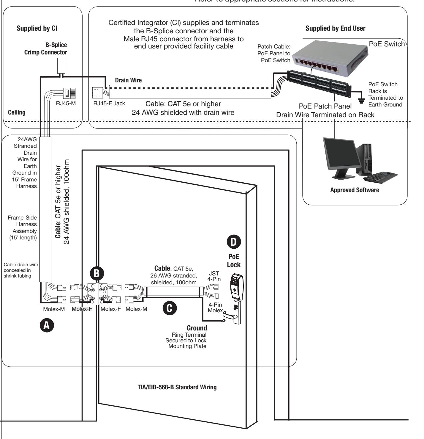
1. PIP (PoE) Installation Wiring:
- PoE Frame harness assembly (From McKinney)
- PoE data hinge (Patent Pending) (From McKinney)
- PoE Door harness* (From McKinney)
-
Access 800 PIP (PoE Lock)
- * Order of installation may vary. Refer to appropriate sections for instructions.
7) PIP (PoE) Installation Wiring (Continued)
A Frame Harness Installation
RJ45-M
Ceiling
24AWG Stranded Drain Wire for Earth Ground in 15' Frame Harness
Frame-Side Harness Assembly (15' length)
Cable drain wire concealed in shrink tubing
B-Splice Crimp Connector
Supplied by CI
Molex-M Cable : CAT 5e or higher 24 AWG shielded, 100ohm
Components and wire harness supplied by McKinney: Suggested installation.
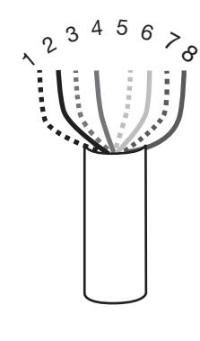
Cut end / ceiling-side PoE harness:
TIA/EIB-568-B Standard Wiring
| Pair Number | Wire | PIN | |
|---|---|---|---|
| 1 | White/Blue | White/Blue | 5 |
| Blue | 4 | ||
| 2 | White/Orange | White/Orange | 1 |
| Orange | 2 | ||
| 3 | White/Green | White/Green | 3 |
| Green | 6 | ||
| 4 | White/Brown | White/Brown | 7 |
| Brown | 8 |
Do not confuse pair numbers with pin numbers. A pair number is used for reference only (eg: 10BaseT Ethernet uses pairs 2 & 3). The pin numbers indicate actual physical locations on the plug and jack.
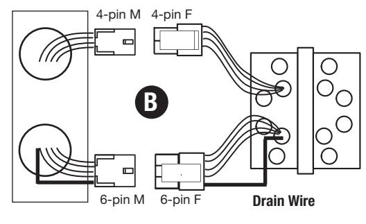
B Hinge side of PoE harness:
- 1. Feed cut end of harness into hole on hinge-side through single access hole.
- 2. Push one of the connectors back through hole and feed into separate access hole.
Each of the hinge-side harness connectors should end up threaded through a different access hole and matched to the same size pin connector from the door harness:
- 4-pin male Molex connector.
- 6-pin male Molex connector with ground wire.
Notes:
- Connectors only go on one way. They cannot be plugged to incorrect position.
- Do not force and do not offset connectors.
- Be sure they are completely seated (flush).
Hinge-side harness connectors:
- 4-pin male molex connector
- 6-pin male molex connector with ground wire
Lock-side harness connectors:
- Ring terminal
- (2) 4-pin connectors
Frame PoE Hinge (Patent Pending)

7) PIP (PoE) Installation Wiring (Continued)
C Hinge Installation
Order of installation may vary. Refer to appropriate sections for instructions.
Hinge-side harness connectors:
- 4-pin male Molex connector
- 6-pin male Molex connector with ground wire
Lock-side harness connectors:
- Ring terminal
-
(2) 4-pin connectors:
- 4-pin Molex connector
- 4-pin connector
Notes:
• Connectors go on only one way. They cannot be plugged to incorrect position.
Drain Wire
Do not force and do not offset connectors.

PoE Hinge (Patent Pending)
Door Harness Installation
Order of installation may vary. Refer to appropriate sections for instructions.
6-pin M
- 1. Prop door open.
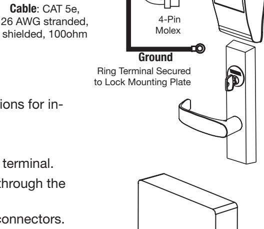
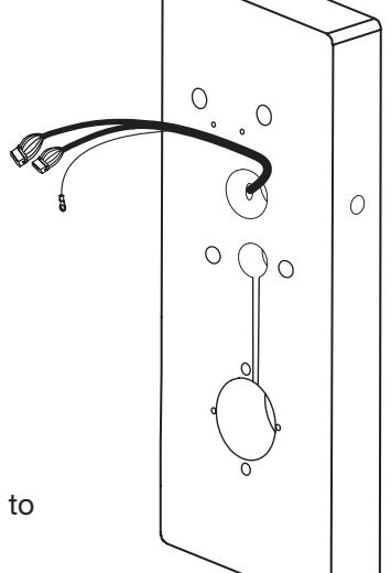
- 2. Tape the two lock-side 4-pin connectors to the ring terminal.
- 3. Using the ring terminal, carefully fish the assembly through the door channel to the lock.
- 4. Remove tape from ring terminal and door harness connectors.
Hinge-side harness connectors:
- 4-pin male Molex connector
- 6-pin male Molex connector with ground wire
Lock-side harness connectors:
- Ring terminal
-
(2) 4-pin connectors:
- 4-pin Molex connector
- 4-pin connector
Notes:
- Connectors go on only one way. They cannot be plugged to incorrect position.
- Do not force and do not offset connectors.
- Be sure they are completely seated (flush).
JST
4-Pin

Corbin Russwin, Inc. 225 Episcopal Road Berlin, CT 06037-4004 USA 800-810-WIRE (9473) • www.corbinrusswin.com

Corbin Russwin, Inc. 225 Episcopal Road Berlin, CT 06037-4004 USA 800-810-WIRE (9473) • www.corbinrusswin.com