Corbin Russwin Access 800 TCAC2 WM800 Installation Instructions_FM233
Open the original PDF document
View PDF

ASSA ABLOY
Installation Instructions for WM800 Reader / Controller

FM233 11/18
Attention Installer
! WARNING
This product can expose you to lead which is known to the state of California to cause cancer and birth defects or other reproductive harm. For more information go to www.P65warnings.ca.gov.
08/2018
For installation assistance, contact Corbin Russwin, Inc., at 1-800-810-WIRE (9473)

<u>Table of Contents –WM800 Reader / Controller</u>
| Section 1: Introduction | |
|---|---|
| 1.1 General Description/Requirements | 3 |
| 1.2 System Requirements | |
| 1.3 Description/Features | 4 |
| 1.4 Supplied Parts/Optional Items | 5 |
| 1.5 WM800 Specifications | 6 |
| Section 2: Installation | |
| 2.1 WM800 Component Overview | 8 |
| 2.2 Performing a Wall Mount Installation | 9 |
| 2.3 Preventing Possible Water Problems | 10 |
| 2.4 Performing a Glass Mount Installation | 11 |
| 2.5 Performing a Secure Installation (Keypad/controller away from prox antenna) | 12 |
| Section 3: Wiring | |
| 3.1 Connecting the Communication Board to the Main Control Board | 15 |
| 3.2 Main Control Board Wiring Connection Overview | 16 |
| 3.3 Communication Board Wiring Connection Overview | 17 |
| 3.4 Wiring the Main Relay to Fail Secure Lock | 18 |
| 3.5 Wiring the Main Relay to Fail Safe Lock | 19 |
| 3.6 Wiring the Auxiliary Relay for Alarm Shunt | 20 |
| 3.7 Wiring the Auxiliary Relay for Door Ajar or Forced Door Alarm | 21 |
| 3.8 Wiring the REX (Request to Exit) Switch | 22 |
| Section 4: Programming | |
| 4.1 Default Settings | 23 |
| 4.2 User Type Definitions | 24 |
| 4.3 Program Commands | |
| 4.4 LED Indicators/Sounder Operations | |
| 4.5 Testing the Controller/Keypad |

Section 1: Introduction
1.1 General Description/Requirements
This equipment is designed to be installed and serviced by security and lock industry professionals.
Access system programming: This access system possesses infrared communications capability and can be managed as part of an overall access control system with Accessware<sup>TM</sup> software. See section 1.2 for system requirements.
Optional Keypad Programming: The WM800 unit can be programmed manually using the keypad on each unit and without the use of a personal computer (PC) and software. This manual contains the optional keypad programming instructions (section 4). Keypad programming can be helpful to get a door or doors up and running prior to having the availability of the host computer. In all cases, the personal computer programming options supersede the keypad programming options.
Information to User
Any changes or modifications not expressly approved by the party responsible for compliance could void the user's authority to operate the equipment.
1.2 System Requirements
Access system programming -System Requirements
• Accessware<sup>TM</sup> PC with Access HH PDA software
PC Hardware Requirements
- IBM-compatible Pentium-class computer
- 30MB available hard disk space
- VGA monitor or better, 800x 600 resolution recommended
- CD-ROM or DVD-ROM drive
- Mouse
Operating System List
Windows 98; Windows 2000; Windows XP

* Image Must Be Used - CANNOT Be Typed
* Must Be Used On All Single Page and Multiple Page Installation Instruction Sheets
* Must Be Used On The Bottom Left Of ALL ONE PAGE Installation Instruction Sheets
* It is NOT USED On The Back Page Or Back Cover Of Installation Instruction Sheets
* A 2 line Version and a 5 Line Version Of The Corporate Statement Image Are Available
* Must Be Used On The Bottom of ALL ONE PAGE Installation Instruction Sheets
Copyright © 2008 Corbin Russwin, Inc., an ASSA ABLOY Group company. All rights reserved.
Reproduction in whole or in part without the express written permission of Corbin Russwin, Inc. is prohibited.
Note: Marketing will continue to be part of the instruction sheet and template reviewing process
* Must Be Used On The Bottom of The BACK PAGE OR BACK COVER Of All Multiple Page Installation Instruction Sheets
* Must Be Used On The Bottom Left Of ALL INSIDE PAGES of Multiple Page Installation Instruction Sheets
Installation and Wiring Instructions for Corbin Russwin WM800
1.3 Description/Features
The WM800 unit is a single opening (single or pair of doors) access system that is managed from a personal computer using Accessware™ software. The unit is equipped with infrared communications which allow the unit to be programmed with Access HH PDA software. In addition, the unit can be programmed manually with its keypad. * Image Must Be Used - CANNOT Be Typed Corporate Statement * Must Be Used On The BACK PAGE Or BACK COVER Of All Multiple Page Installation Instruction Sheets
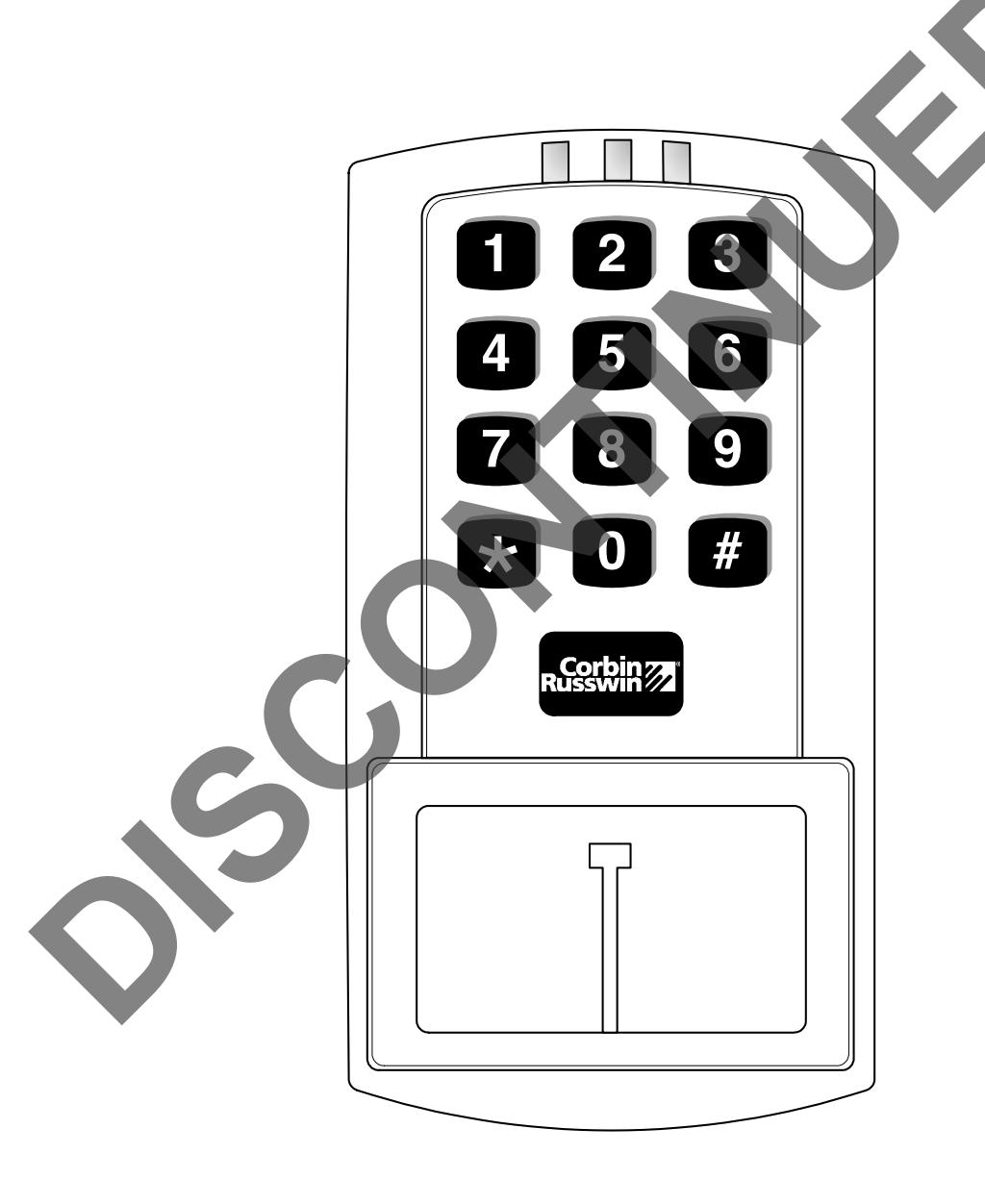
The WM800 unit is unique since no separate controller is needed and there is no need to run cables from a reader to a controller. The unit is self-contained and includes built in HID proximity technology, a keypad, and the controller.
Important features include:
- Managed with Accessware™ software loaded on a PC (personal computer)
- Programmed with Access HH PDA software
- No separate controller to install
- Eliminate costly reader wiring
- 2000 users per door
- 2000 event audit trail
- Integrated-HID proximity reader
- Card, code, card and code (Card = proximity card, fob or tag)
- Can locate proximity antenna 10 ft from controller
- Indoor and outdoor (gasket included) applications
- Glass mount kit
- Door monitor relay
- Main relay for lock
- Programmable auxiliary relay (For Alarm Shunt, Door Ajar, or Forced Door)
- Local sounder for alerts
- Internal and external REX (Request to Exit) capability
* Image Must Be Used - CANNOT Be Typed
Branding Guidelines For Installation Instruction Sheets
* Must Be Used On All Single Page and Multiple Page Installation Instruction Sheets
* Must Be Used On The Bottom Left Of ALL ONE PAGE Installation Instruction Sheets
* It is NOT USED On The Back Page Or Back Cover Of Installation Instruction Sheets
* Must Be Used On The Bottom Left Of ALL INSIDE PAGES of Multiple Page Installation Instruction Sheets
Endorsed Logo

* Image Must Be Used - CANNOT Be Typed
* Must Be Used On All Single Page and Multiple Page Installation Instruction Sheets
* Must Be Used On The Bottom Left Of ALL ONE PAGE Installation Instruction Sheets
* It is NOT USED On The Back Page Or Back Cover Of Installation Instruction Sheets
* Must Be Used On The Bottom Left Of ALL INSIDE PAGES of Multiple Page Installation Instruction Sheets
Installation and Wiring Instructions for Corbin Russwin WM800
1.4 Supplied Parts/Optional Items
Quantity Description
| 1 |
Keypad/control unit assembly with Prox Sensor, Backplate, hex socket
Corporate Statement screw * Must Be Used On The BACK PAGE Or BACK COVER Of All Multiple Page Installation Instruction Sheets |
| 1 |
* Image Must Be Used - CANNOT Be Typed
* A 2 line Version and a 5 Line Version Of The Corporate Statement Image Are Available Filler Piece/REX Button |
| 1 | Press to Exit Label |
| 4 | Wall Anchors |
| 4 | Mounting Screws |
| 1 | Antenna Backplate for remote mounting |
| 1 | Silicone Rubber dogbone |
| 4 | Self-Adhering Pads (for glass mounting) |
| 1 |
Installer Guide
Copyright Statement |
| 4 |
* Must Be Used On The Bottom of ALL ONE PAGE Installation Instruction Sheets
Cable Assemblies * Must Be Used On The Bottom of The BACK PAGE OR BACK COVER Of All Multiple Page Installation Instruction Sheets |
| 1 |
* Copy Can Be Typed
Tamper Screw (spanner) Copyright © 2008 Corbin Russwin, Inc., an ASSA ABLOY Group company. All rights reserved. |
| 1 |
Reproduction in whole or in part without the express written permission of Corbin Russwin, Inc. is prohibited.
Gasket |
|
Optional Items
Note: Marketing will continue to be part of the instruction sheet and template reviewing process |
|
| Replacement Battery: Panasonic BR1225 or equivalent | |
| Accessware™ PC software with Access HH PDA software | |
| ISO Prox II | |
| ProxCard II | |
| DuoProx II | |
| MicroProx tag | |
| ProxKey II | |
* Image Must Be Used - CANNOT Be Typed
Branding Guidelines For Installation Instruction Sheets
* Must Be Used On All Single Page and Multiple Page Installation Instruction Sheets
* Must Be Used On The Bottom Left Of ALL ONE PAGE Installation Instruction Sheets
* It is NOT USED On The Back Page Or Back Cover Of Installation Instruction Sheets
* Must Be Used On The Bottom Left Of ALL INSIDE PAGES of Multiple Page Installation Instruction Sheets
Endorsed Logo

* Must Be Used On All Single Page and Multiple Page Installation Instruction Sheets
* Must Be Used On The Bottom Left Of ALL ONE PAGE Installation Instruction Sheets
* It is NOT USED On The Back Page Or Back Cover Of Installation Instruction Sheets
* Must Be Used On The Bottom Left Of ALL INSIDE PAGES of Multiple Page Installation Instruction Sheets
Installation and Wiring Instructions for Corbin Russwin WM800
1.5 WM800 Specifications
| ELECTRICAL |
* Image Must Be Used - CANNOT Be Typed
12 or 24 VDC, linear filtered and regulated power supply |
| 500 mA (not including locking device or peripherals) | |
|
WIRING
(by others) |
Corporate Statement |
| Remote Antenna Cable |
* Must Be Used On The BACK PAGE Or BACK COVER Of All Multiple Page Installation Instruction Sheets
ALPHA 1174C (22AWG) 4-wire, stranded * Image Must Be Used - CANNOT Be Typed |
|
* A 2 line Version and a 5 Line Version Of The Corporate Statement Image Are Available
(this is required ONLY if you choose to remote the |
|
| antenna 10 feet Max away from the keypad/controller) | |
| Power Supply Cable | 18AWG -22AWG 2-wire stranded (depends on distance) |
| Door Lock Cable | 18AWG -22AWG 2-wire stranded (depends on distance) |
| Door Monitor Cable | 18AWG -22AWG 2-wire stranded (depends on distance) |
| REX Cable | (If using remote switch) 2-wire stranded |
| MECHANICAL | |
| Height |
5.25 in (13.3 cm)
Copyright Statement |
| Width |
* Must Be Used On The Bottom of ALL ONE PAGE Installation Instruction Sheets
2.75 in (7 cm) * Must Be Used On The Bottom of The BACK PAGE OR BACK COVER Of All Multiple Page Installation Instruction Sheets |
| Depth |
* Copy Can Be Typed
1.375 in (3.5 cm) |
| RELAY OUTPUT |
Copyright © 2008 Corbin Russwin, Inc., an ASSA ABLOY Group company. All rights reserved.
Reproduction in whole or in part without the express written permission of Corbin Russwin, Inc. is prohibited. |
|
Main Relay (switches up to 2A)
Note: Marketing will continue to be part of the instruction sheet and template reviewing process |
|
| Aux Relay (switches up to 2A) | |
| MONITOR INPUTS | |
| Door Position (Normally Closed, dry contact) | |
| Request to Exit (REX, Normally Open, dry contact) | |
| LEDs | Bi-Color (red/green) |
| Yellow | |
| COMPATIBLE | Any HID card can be programmed by keypad presentation. |
| PROXIMITY | HID 26, 33, 34-bit, and corporate 1000 (35-bit) cards can |
| CARDS | be programmed through software |
* Image Must Be Used - CANNOT Be Typed
Branding Guidelines For Installation Instruction Sheets
* Must Be Used On All Single Page and Multiple Page Installation Instruction Sheets
* Must Be Used On The Bottom Left Of ALL ONE PAGE Installation Instruction Sheets
* It is NOT USED On The Back Page Or Back Cover Of Installation Instruction Sheets
* Must Be Used On The Bottom Left Of ALL INSIDE PAGES of Multiple Page Installation Instruction Sheets
Endorsed Logo

* Must Be Used On All Single Page and Multiple Page Installation Instruction Sheets
* Must Be Used On The Bottom Left Of ALL ONE PAGE Installation Instruction Sheets
Installation and Wiring Instructions for Corbin Russwin WM800
| UNIT CAPACITY |
* Must Be Used On The Bottom Left Of ALL INSIDE PAGES of Multiple Page Installation Instruction Sheets
* It is NOT USED On The Back Page Or Back Cover Of Installation Instruction Sheets |
|
|---|---|---|
| Users |
2,000 users maximum; each user can have a card/tag, a
* Image Must Be Used - CANNOT Be Typed |
|
| PIN code, or a card/tag plus a PIN code | ||
| Audit Trail | 2,000 transactions maximum; each transaction includes, | Corporate Statement |
| Transactions | date, time, user, site, door, event, serial # | * Must Be Used On The BACK PAGE Or BACK COVER Of All Multiple Page Installation Instruction Sheets |
| Lock Time |
1-
255 seconds |
* Image Must Be Used - CANNOT Be Typed
* A 2 line Version and a 5 Line Version Of The Corporate Statement Image Are Available |
| Lock Mode | Access Time or Passage | |
| ALARM OUTPUT | One of these three events can be programmed: Alarm | |
| Shunt Relay, Forced Door Relay or Door Ajar Relay | ||
| USER ACCESS | ||
| CONFIGURATIONS | ||
| Code ONLY | ||
| Card ONLY | ||
| Code OR Card | Copyright Statement | |
| Code AND Card | * Must Be Used On The Bottom of ALL ONE PAGE Installation Instruction Sheets | |
| PROGRAMMABLE |
Each user is assigned one of the following user types:
* Copy Can Be Typed |
* Must Be Used On The Bottom of The BACK PAGE OR BACK COVER Of All Multiple Page Installation Instruction Sheets |
| USER TYPES | Copyright © 2008 Corbin Russwin, Inc., an ASSA ABLOY Group company. All rights reserved. | |
| 0-Passage | Reproduction in whole or in part without the express written permission of Corbin Russwin, Inc. is prohibited. | |
| 1-Standard access | Note: Marketing will continue to be part of the instruction sheet and template reviewing process | |
| 3-Lockout | ||
| 4-Extended time | ||
| 5-Single use | ||
| 6-Relock | ||
| 7-Emergency | ||
| 8-Communication unlock | ||
| SYSTEM USES/ | Suitable for remote locations,indoors or outdoors, | |
| INSTALLATION | wall mounted, glass mounted, or secure installation | |
| CONFIGURATIONS | ||
| ENVIRONMENTAL | Indoor or outdoor | |
| Operating | -22° to 150° F (-30° to 65° C) for 12 VDC Operation | |
| Temperature | -22° to 122° F (-30° to 50° C) for 24 VDC Operation | |
| Operating Humidity | 5% to 95% relative humidity, non-condensing |
* Image Must Be Used - CANNOT Be Typed
Branding Guidelines For Installation Instruction Sheets
* Must Be Used On All Single Page and Multiple Page Installation Instruction Sheets
* Must Be Used On The Bottom Left Of ALL ONE PAGE Installation Instruction Sheets
* It is NOT USED On The Back Page Or Back Cover Of Installation Instruction Sheets
* Must Be Used On The Bottom Left Of ALL INSIDE PAGES of Multiple Page Installation Instruction Sheets
Endorsed Logo

* Image Must Be Used - CANNOT Be Typed
* Must Be Used On All Single Page and Multiple Page Installation Instruction Sheets
* Must Be Used On The Bottom Left Of ALL ONE PAGE Installation Instruction Sheets
* It is NOT USED On The Back Page Or Back Cover Of Installation Instruction Sheets
* Must Be Used On The Bottom Left Of ALL INSIDE PAGES of Multiple Page Installation Instruction Sheets
Installation and Wiring Instructions for Corbin Russwin WM800
Section 2: Installation
2.1 WM800 Component Overview
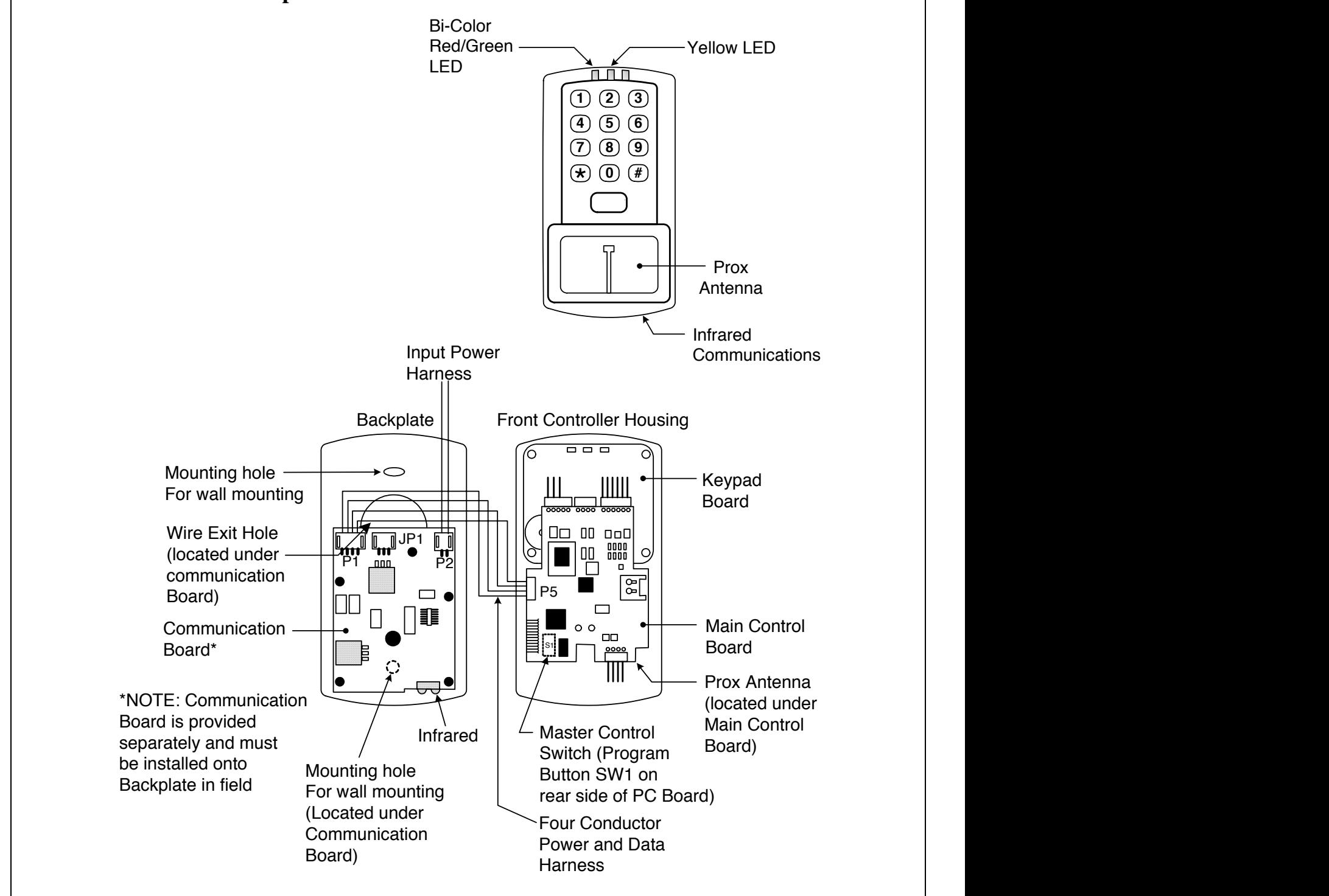
Figure 1 WM800 Component Overview
* Image Must Be Used - CANNOT Be Typed
* Must Be Used On The Bottom Left Of ALL ONE PAGE Installation Instruction Sheets
* It is NOT USED On The Back Page Or Back Cover Of Installation Instruction Sheets
* Must Be Used On The Bottom Left Of ALL INSIDE PAGES of Multiple Page Installation Instruction Sheets
Endorsed Logo

2.2 Performing a Wall Mount Installation
Typically, the WM800 unit is mounted on a flat, surface (drywall, masonry, wood, etc.). A single-gang electrical box (or back box) can be used. Typically, the WM800 unit is wall mounted outside the access area on the unsecure side of the door. Figure 2 illustrates the backplate on the WM800 unit used for wall mounting. Two single-gang box holes align with two corresponding holes in the single-gang box. A wire
- 1. Secure a single-gang box to the desired location.
- 2. Punch out the two holes for single-gang box connectors (Figure 2) on the controller backplate of the WM800 unit. Punch out wiring exit hole(s) as required.
- 3. Disconnect the controller backplate of the WM800 unit from the front keypad/controller. Align the two single-gang box connectors on the controller backplate over the two corresponding holes on the single-gang box, previously secured at step 1.
- 4. Secure the backplate to the single-gang box by inserting/tightening two screws into the two single-gang box holes. For exterior applications, install the supplied gasket between the WM800 backplate and wall (Figure 3).
- 5. Pull the WM800 wiring through the wiring exit holes as appropriate.
exit knockout is supplied through which the WM800 wiring is pulled.
- 6. Install the communication board onto the controller backplate using the supplied five screws.
- 7. Refer to Wiring Instructions (section 3), to connect the communication board to the main controller board and appropriate wiring for the application.
- 8. Connect the front keypad/controller to the back housing.
- 9. Install either the hex screw using the supplied hex wrench or the spanner screw supplied in the hardware pack. Use a #6 spanner bit (not included) for the spanner screw.
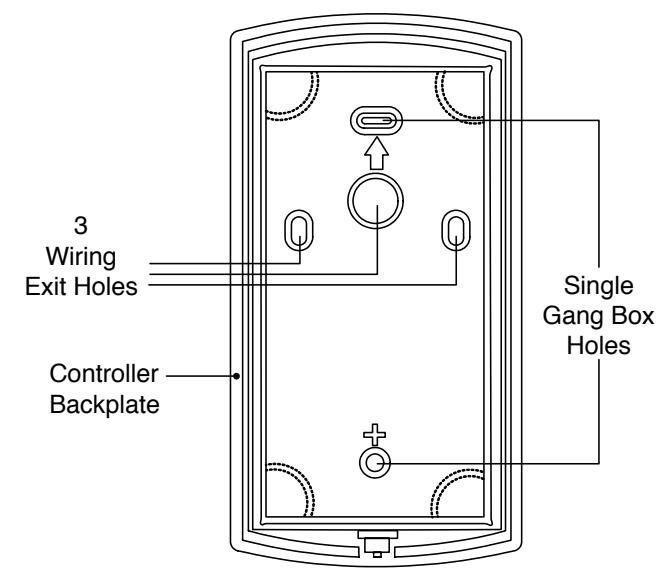
Figure 2 Backplate

* Image Must Be Used - CANNOT Be Typed
* Image Must Be Used - CANNOT Be Typed
* Must Be Used On All Single Page and Multiple Page Installation Instruction Sheets
* Must Be Used On The Bottom Left Of ALL ONE PAGE Installation Instruction Sheets
* It is NOT USED On The Back Page Or Back Cover Of Installation Instruction Sheets
* A 2 line Version and a 5 Line Version Of The Corporate Statement Image Are Available
* Must Be Used On The Bottom of ALL ONE PAGE Installation Instruction Sheets
Copyright © 2008 Corbin Russwin, Inc., an ASSA ABLOY Group company. All rights reserved.
Reproduction in whole or in part without the express written permission of Corbin Russwin, Inc. is prohibited.
Note: Marketing will continue to be part of the instruction sheet and template reviewing process
* Must Be Used On The Bottom Left Of ALL INSIDE PAGES of Multiple Page Installation Instruction Sheets
* Must Be Used On The BACK PAGE Or BACK COVER Of All Multiple Page Installation Instruction Sheets
* Must Be Used On The Bottom of The BACK PAGE OR BACK COVER Of All Multiple Page Installation Instruction Sheets
Installation and Wiring Instructions for Corbin Russwin WM800
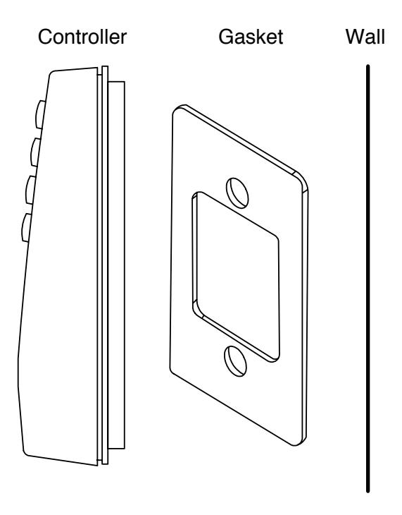
Figure 3 Gasket Installation/Exterior Applications
2.3 Preventing Possible Water Problems
To avoid damage to electronics caused by water when used on exterior applications, follow these instructions carefully.
- 1. Do NOT seal the cover and base together. Keypads are designed to direct any water that enters the two constituent pieces, base and cover, towards the bottom and out a drain or weep hole.
- 2. Use the supplied gasket for exterior applications.
- 3. Use silicone to seal wire runs and mounting holes.
- 4. Bend the wires before they enter the case to form a drip loop. Water can follow the wires to the connection point of the circuit board and short out the terminals to which the wires are connected.
* Image Must Be Used - CANNOT Be Typed
Branding Guidelines For Installation Instruction Sheets
* Must Be Used On All Single Page and Multiple Page Installation Instruction Sheets
* Must Be Used On The Bottom Left Of ALL ONE PAGE Installation Instruction Sheets
* It is NOT USED On The Back Page Or Back Cover Of Installation Instruction Sheets
* Must Be Used On The Bottom Left Of ALL INSIDE PAGES of Multiple Page Installation Instruction Sheets
Endorsed Logo

2.4 Performing a Glass Mount Installation
Figure 4 shows the four pressure-sensitive adhesive pads and the two side cut-outs used for this installation. In this configuration, the WM800 unit is affixed with the four self-adhesive pads to the glass or the glass window adjacent to the controlled door being accessed, on the interior side of the glass. One of the two side cut-outs is used to bring the wires out of the side of the WM800 case.
- 1. Disconnect the back housing from the front keypad/controller. Remove the tape from the four self-adhesive pads on the back housing and apply the pads to the four corners of the backplate.
- 2. Affix the back housing to the glass door or the glass window adjacent to the controlled door being accessed on the interior side of the glass.
- 3. Determine which of the two side cut-outs on the back housing to use for the wiring and open that cut-out using the appropriate cutting tool.
- 4. Pull the wiring through the selected side cut-out as required.
- 5. Install the communication board onto the controller backplate using the five screws provided.
- 6. Refer to Wiring Instructions (section 3), connect the communication board to the main controller board and appropriate wiring for the application.
- 7. Connect the front keypad/controller to the back housing.
- 8. Install either the hex screw using the supplied hex wrench or the spanner screw supplied in the hardware pack. Use a #6 spanner bit (not included) for the spanner screw.
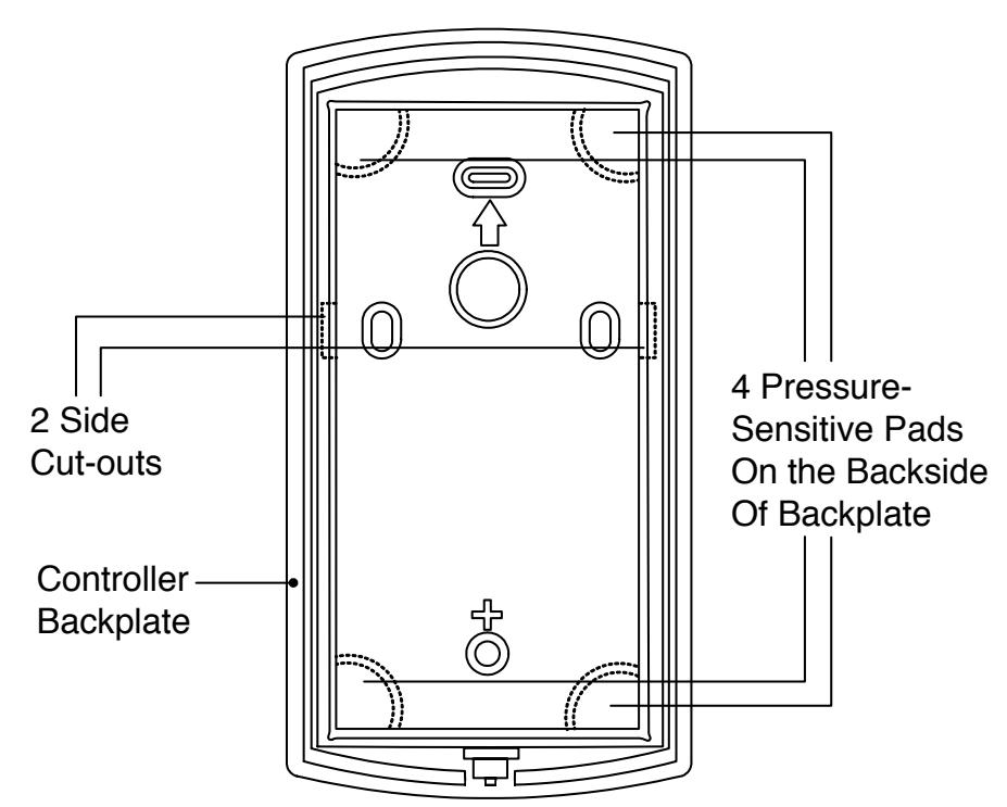
Figure 4 Performing a Glass Mount Installation

2.5 Performing a Secure Installation (keypad/controller away from prox antenna)
In this configuration, the WM800 prox sensor housing is removed from the keypad/controller and located a maximum of 10 feet away. The controller/keypad is located inside a secure area.
-
1. Disconnect the backplate of the WM800 unit from the front keypad/controller.
- When handling the main printed circuit board, to guard against possible static discharges, touch a grounded object BEFORE touching the WM800 unit. Remove the main printed circuit board by pressing the two spring tabs in the direction of the arrows as shown in Figure 5. Be careful with the wires.
- Pull on the main circuit board and remove Pin connector P4 (a 4-pin connector) from the bottom of the main board. A ribbon cable now holds the main board to the keypad board. DO NOT pull this ribbon cable out of its connector! Once the main board is removed, you can access the interior of the antenna.
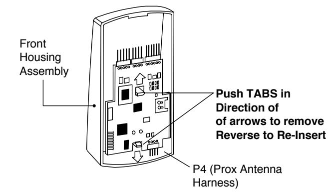
Figure 5 Removing/Inserting Printed Circuit Board
2. Remove the antenna housing from the keypad/controller by pressing the four secure tabs inward (see Figure 6) until the sensor housing pops out.
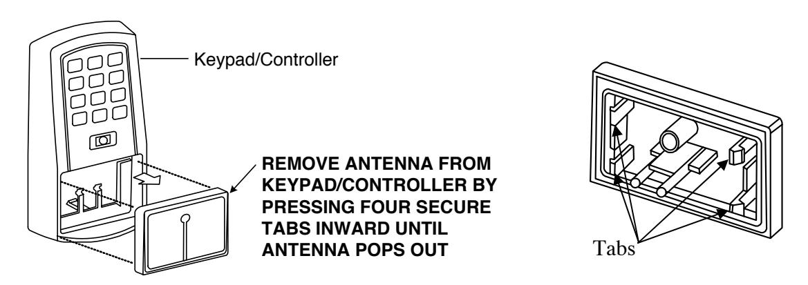
Figure 6 Removing Prox Antenna

-
3. Prepare the wiring and extension wiring as follows:
- Cut off the plastic connector of the WM800 sensor housing harness (Figure 7).
- Splice the recommended remote antenna cable Alpha 1174C (22AWG), field supplied 10-foot maximum length , to the properly cut antenna cable using standard electrical techniques.
REMOTE INSTALLATION SITE
MAX 10 feet from Keypad / Controller
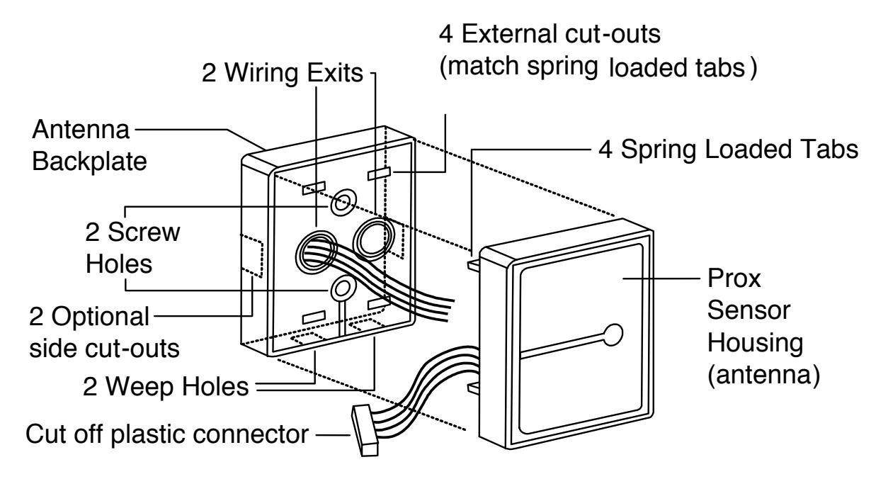
Figure 7 Remote Installation of Prox Antenna
-
4. Mount the antenna backplate in a vertical orientation (Figure 7) and secure it to the wall through the two screw holes using the two screws provided. Ensure that the two weep holes, provided to remove possible moisture, are positioned on the bottom. The wiring exits in the antenna backplate. (Four external cut-outs on the antenna backplate match the four spring-loaded tabs on the antenna.)
NOTE: Two side cut-outs are furnished on the antenna backplate for the wiring, if the
- NOTE: Two side cut-outs are furnished on the antenna backplate for the wiring, if the installation does not permit the wiring to run through the wall. These must be cut out to be used.
- Once the antenna backplate is mounted properly, align the antenna to the backplate and connect the antenna to the antenna backplate. The large tab in the center of the antenna assembly must be broken off before being attached to the antenna backplate.
- 5. Refer to the Wall Mount Installation instructions and Figure 2 for backplate and communication board installation.

- 6. Run the antenna wiring back to the secure keypad/controller and connect it to the main circuit board, using the 10-inch 4-wire harness (red, black, white, and white) that you plug into connector P4 on the controller board. Connect the red wire of the antenna to the red wire of the P4 harness, etc. Seal the wire holes with silicone.
-
7. Select Filler or Request to Exit (REX) operation as follows (Figure 8):
- If you elect to use the filler piece as a REX switch, return to the keypad/controller and break off two tabs on the filler piece as illustrated in Figure 8. The filler piece replaces the antenna on the front of the keypad/controller for secure installations.
- If the filler piece is not to be used as a REX switch, DO NOT remove the two tabs.
- Select Filler or REX operation and affix the appropriate provided label to the filler piece.
For Filler operation, no tabs are broken off the filler piece, which merely sits in place of the remotely located antenna, once the main circuit board and cabling are replaced.
For REX operation , break off the labeled tabs, which allows a spring-loaded tab to engage the REX switch on the main circuit board and open the door.
- Replace the main circuit board into the keypad/controller and Pin connector P4 to the main circuit board.
- Connect the front keypad/controller of the unit to the back housing.
- Secure with a hex socket screw using the supplied hex wrench, or secure with a tamper screw (optional tool required).
NOTE: REX is off by default. It can be turned on manually see page26 step 5, action7.
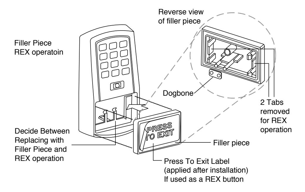
Figure 8 Filler Piece or Internal REX Installation

Section 3: Wiring
3.1 Connecting the Communication Board to the Main Control Board
The WM800 is composed of two circuit boards, the control board and the communication board, which is mounted in the rear keypad housing. The communication board contains the infrared communications circuitry used for communicating to a PDA device, as well as the power supply. The power supply circuit should be powered with 12 or 24 VDC. This is selectable by jumper JP1; 24 VDC is the factory setting. For details, see Figure 9.
The WM800 unit is powered through P2 on the communication board. Connector P1 on the communication board then provides power to the keypad control board using the supplied wire harness; this connects to P5 on the control board. The two data wires for infrared communications are also on this same wire harness. See Figure 9.
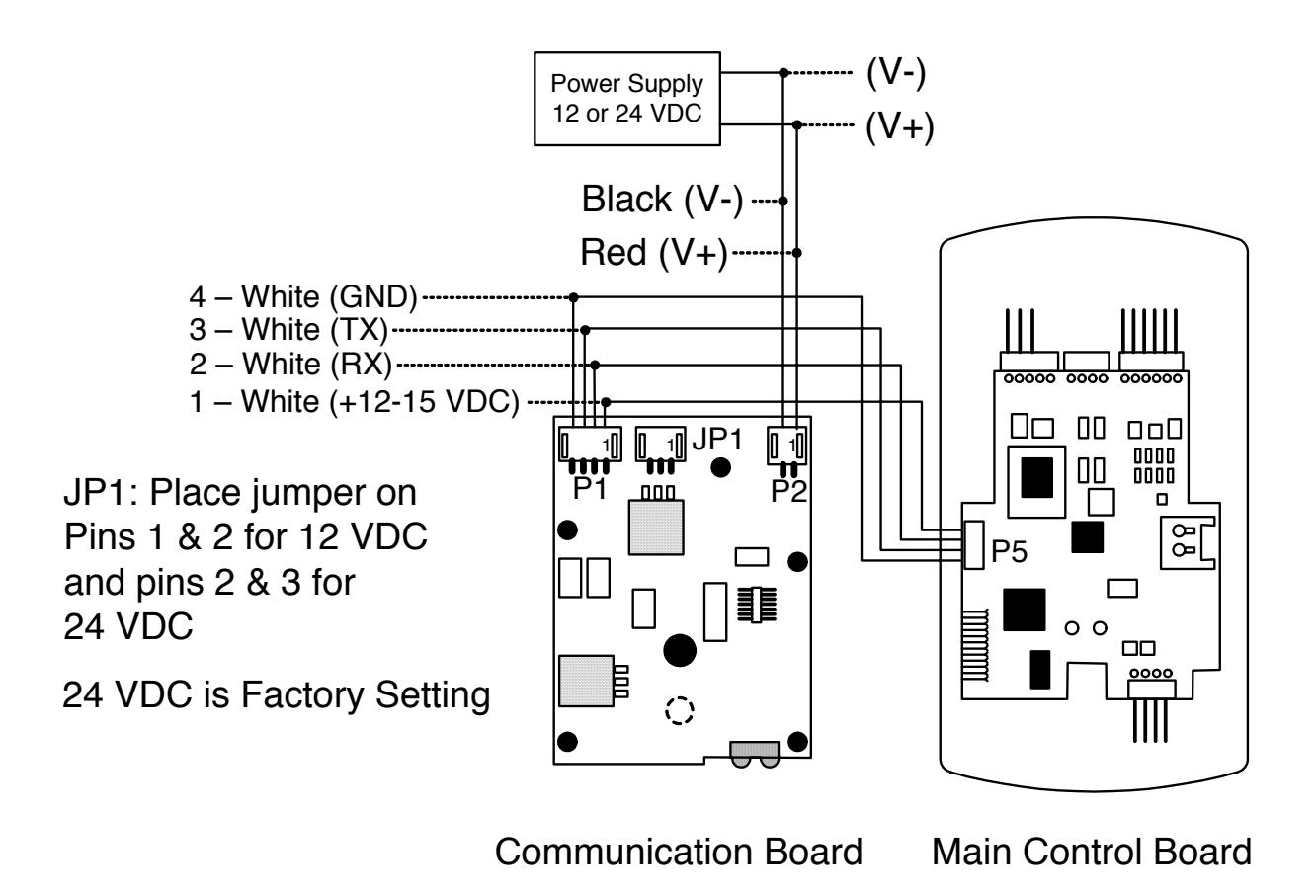
Figure 9 Connecting Communication Board to Main Control Board

3.2 Main Control Board Wiring Connection Overview
Figure 10 below illustrates the Pin connectors on the WM800 main circuit board. Specifications are listed on page 6.
* See Note below
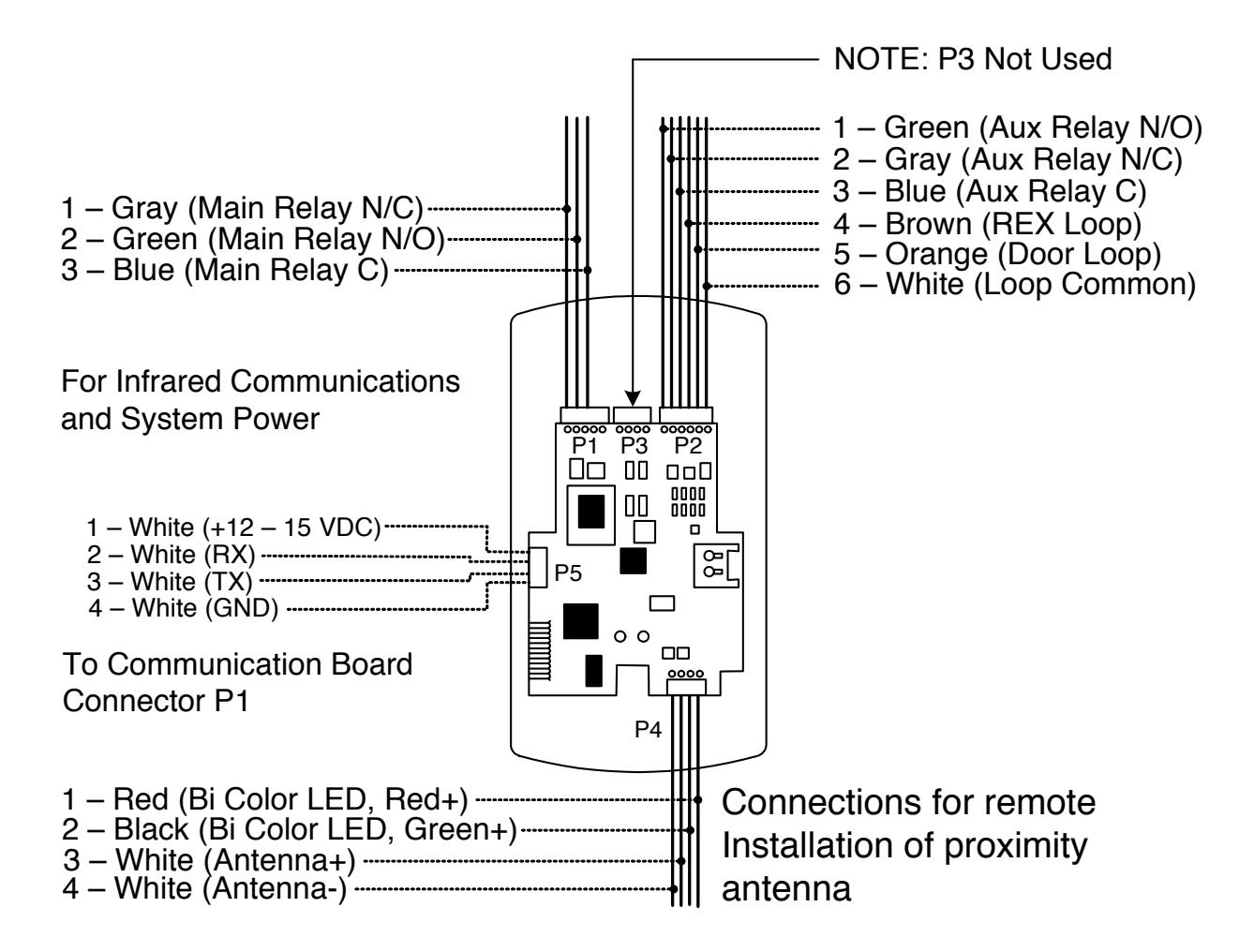
Figure 10 Identifying Pin Connectors (Main Control Board)
NOTE: P2 —Pins 1 and 2 can be wired at the installer's option for one of the following alarm outputs: Alarm Shunt, Forced Door, or Door Ajar.
[Mandatory: If you do not wish to install door contacts, twist the white and orange wires together. If this is not done, REX input will not work.]

3.3 Communication Board Wiring Connections Overview
Figure 11 below illustrates the pin connections on the WM800 communication board.
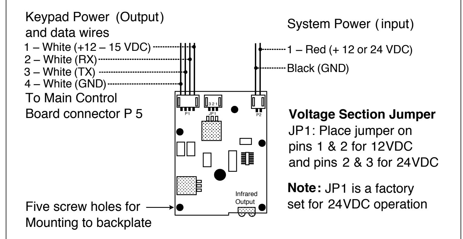
Figure 11 Identifying Pin Connectors (communication board)

3.4 Wiring the Main Relay to Fail Secure Lock
The door lock is wired to connector P1 on the WM800 main circuit board.
Power for the WM800 unit should be powered with a 12 or 24 VDC linear, filtered, and regulated power supply. It is typical for the chosen power supply to power BOTH the WM800 unit and the selected locking device. When using one power supply for both the WM800 unit and locking device, be sure to include both devices in your current requirements calculation.
NOTE: We recommend that you ground the power supply to earth ground.
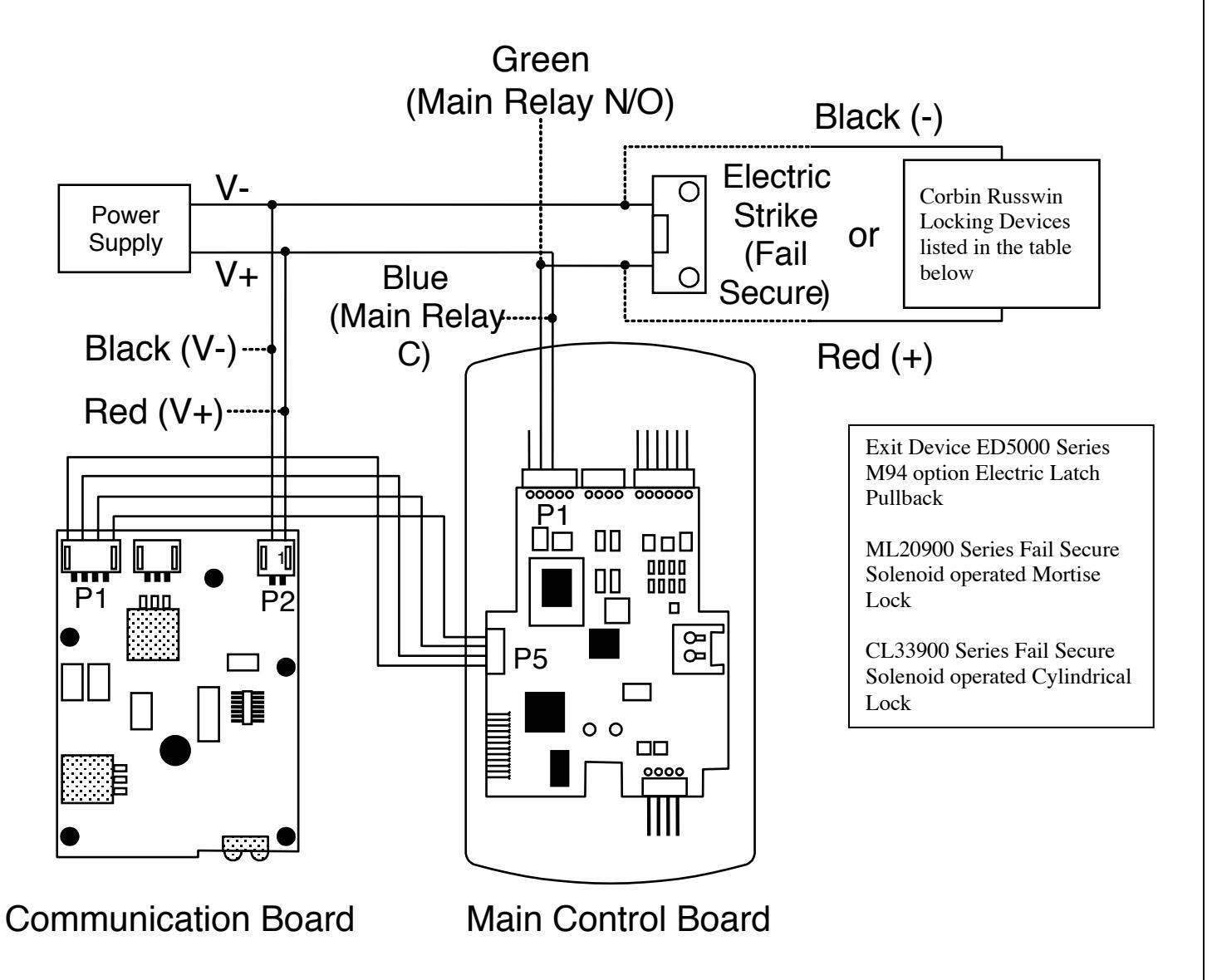
Figure 12 Fail Secure Wiring Diagram

3.5 Wiring the Main Relay to Fail Safe Lock
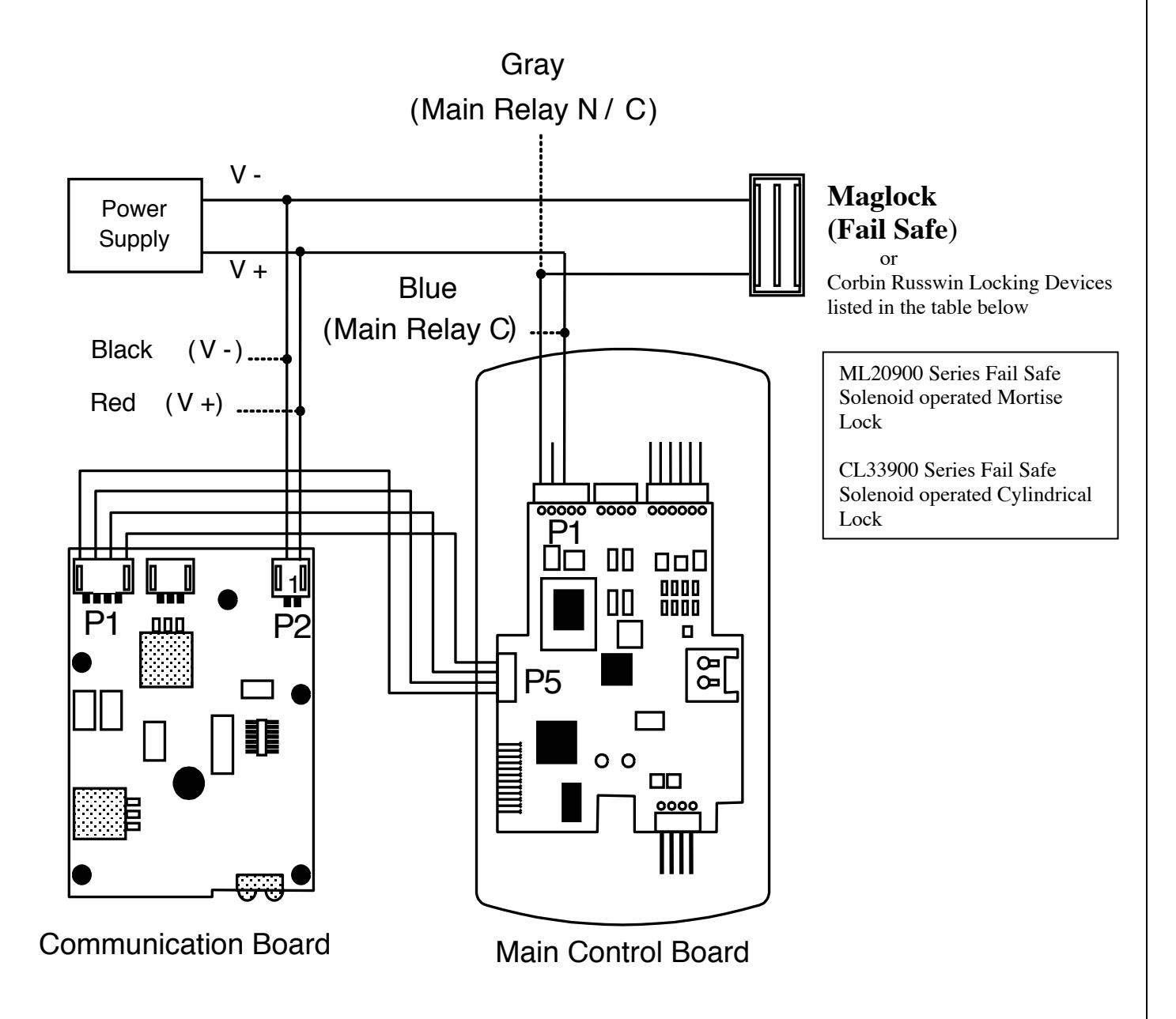
Figure 13 Fail Safe Wiring Diagram

* Image Must Be Used - CANNOT Be Typed
* Must Be Used On All Single Page and Multiple Page Installation Instruction Sheets
* Must Be Used On The Bottom Left Of ALL ONE PAGE Installation Instruction Sheets
* It is NOT USED On The Back Page Or Back Cover Of Installation Instruction Sheets
* Must Be Used On The Bottom Left Of ALL INSIDE PAGES of Multiple Page Installation Instruction Sheets
Installation and Wiring Instructions for Corbin Russwin WM800
3.6 Wiring the Auxiliary Relay for Alarm Shunt
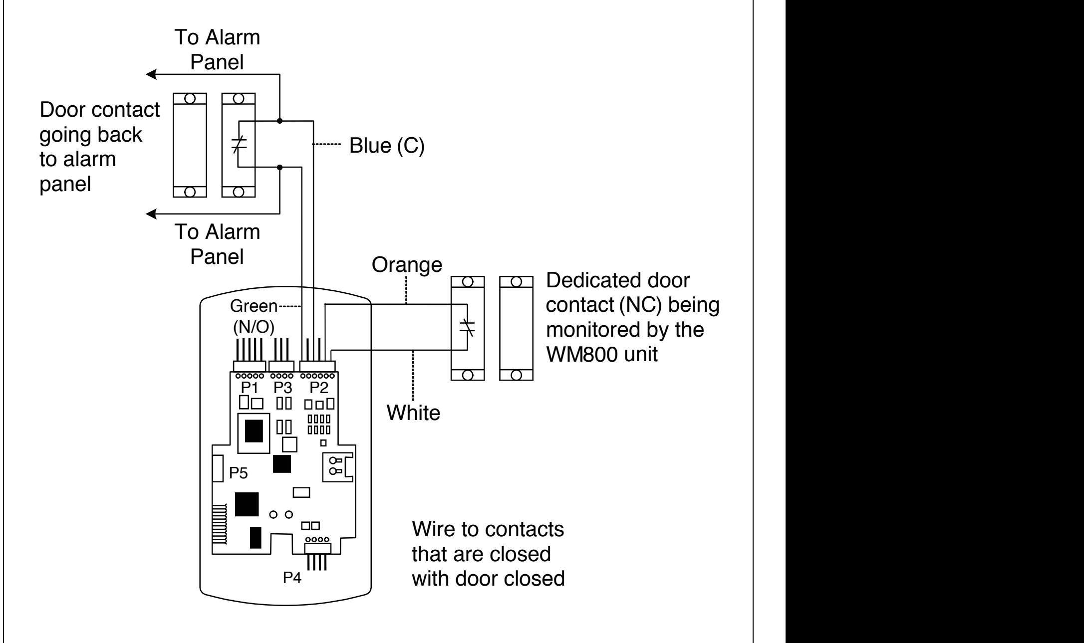
Figure 14 Wiring Auxiliary Relay for Alarm Shunt
* Image Must Be Used - CANNOT Be Typed
Branding Guidelines For Installation Instruction Sheets
* Must Be Used On All Single Page and Multiple Page Installation Instruction Sheets
* Must Be Used On The Bottom Left Of ALL ONE PAGE Installation Instruction Sheets
* It is NOT USED On The Back Page Or Back Cover Of Installation Instruction Sheets
* Must Be Used On The Bottom Left Of ALL INSIDE PAGES of Multiple Page Installation Instruction Sheets
Endorsed Logo

3.7 Wiring the Auxiliary Relay for Door Ajar or Forced Door Alarm
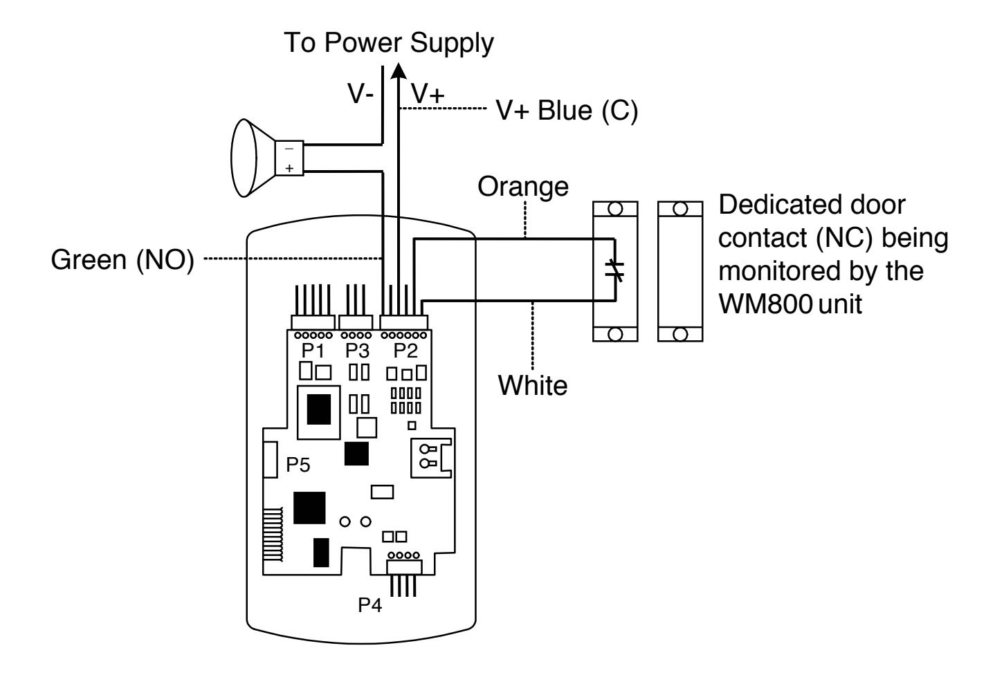
Figure 15 Wiring Auxiliary Relay for Door Ajar/Forced Door Alarm

3.8 Wiring the REX (Request to Exit) Switch
The WM800 unit can be wired to monitor a remote switching device, which is intended to be installed on the secure side of a door. The Request to Exit (REX) loop is a momentary input that engages the lock output for the same length of time for which it is programmed. This feature can be stored in the Transaction Log for viewing.
If you elect to perform a secure installation where the controller is mounted on the secure side of the door, you can use the filler piece as a REX switch. (See page 14, Figure. 8)
Other REX devices can be used to include a remote button placed at a receptionist desk, a press-to-exit switch on the inside of a door, or a passive infrared detector, allowing free and convenient egress. The external REX feature requires no programming; simply wire the unit as illustrated in Figure 16. To incorporate this feature, follow the steps below:
- 1. Turn OFF power to the WM800 unit, and then unlatch the keypad from the plastic housing.
- 2. Locate connector P2 on the main circuit board.
- 3. Plug the 6-conductor harness into connector P2. (NOTE: The 2-pin jumper on pins 5 and 6 of connector P2 must be removed first. SeeFigure 16.)
- 4. If you do not wish to install the door contacts per Figure 16, twist the white wire and the orange wires and wire nut together. This is mandatory. If this is not done, the REX input will not function.
NOTE : The door contact MUST be closed for the REX feature to work properly.
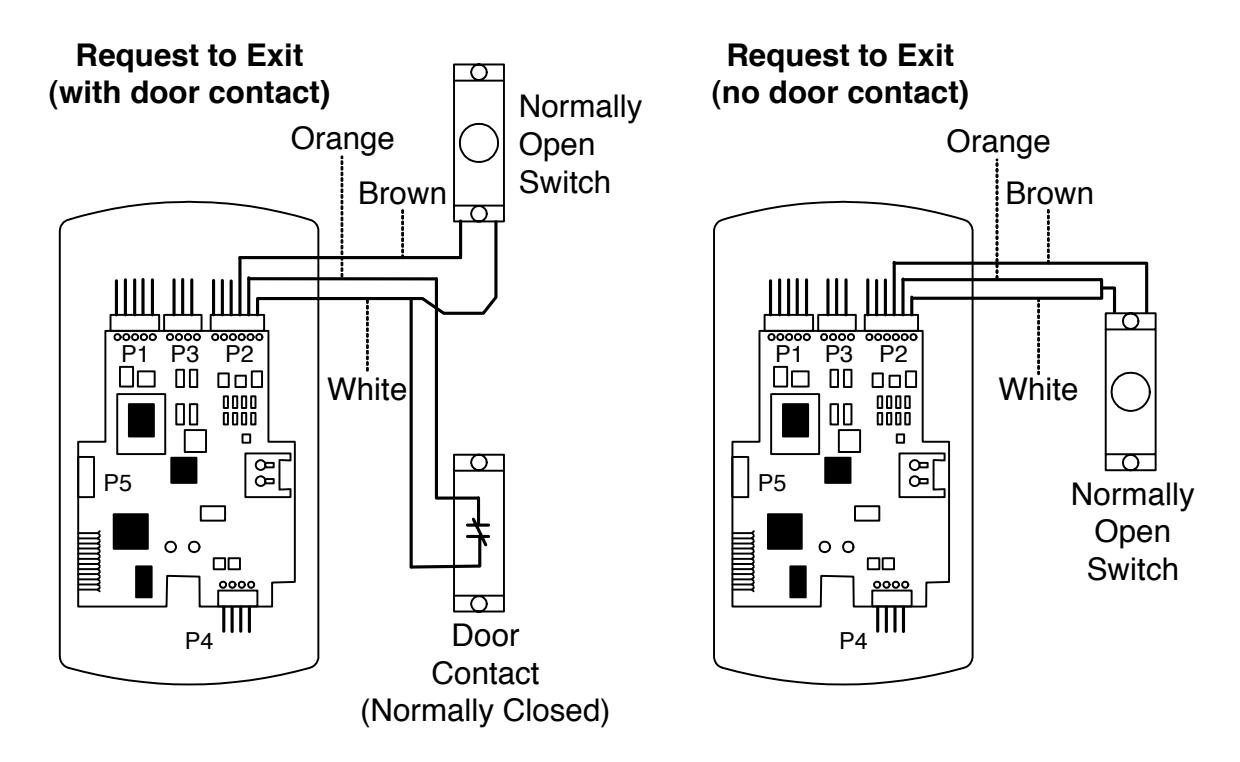
Figure 16 Wiring the REX Switch

Section 4: Programming
4.1 Default Settings
| Parameter | Default Setting |
|---|---|
| Main Relay | Lock Output |
| Auxiliary Relay | Alarm shunt function |
| Audio Alert #1 | Forced Door |
| Audio Alert #2 | Door Ajar |
| Master Code (user one) | 1234 |
| Main Relay energizes for | Five (5) seconds |
| Audible Keypress Feedback | ON |
| Door Ajar Output activates after | Thirty (30) seconds |
| Forced Door Output activates for | Ten (10) seconds |
4.1.1 Master Code
The Master code is a special code stored in user location one. This code can be used to enter program mode, and has access to all programming commands.
"1234" NOTE: "1234" is the default master code, which Corbin Russwin recommends that you change right away. See Section 4.3 Action 1.
4.1.2 Supervisor Code
The Supervisor code is a special code stored in user location two. This code has limited access to Program mode, including commands:
- Adding/Deleting Users (commands #50, #51, #52, #53, #57, and #58)
- Enabling/Disabling Users (command #56)
- Changing Lock Output Time (command #11)
- Changing Keypad Platform Parameters 5 and 6 (command #32)
By default, user location two is empty, which means that if you need a Supervisor code, you must program one.
4.1.3 Master Code and Supervisor Code Notes
The following is a list of items that pertain only to the Master and Supervisor codes:
- The Master and Supervisor codes can only be programmed as standard user types
- The Master and Supervisor codes can be programmed as card AND code or card OR code users.
- The Master and Supervisor codes cannot be programmed as card only.

* Must Be Used On All Single Page and Multiple Page Installation Instruction Sheets
* Must Be Used On The Bottom Left Of ALL ONE PAGE Installation Instruction Sheets
* Must Be Used On The Bottom Left Of ALL INSIDE PAGES of Multiple Page Installation Instruction Sheets
Installation and Wiring Instructions for Corbin Russwin WM800
4.2 Wall Prox User Types
|
User Type
Numeric ID Description Passage 0 Passage user causes the following: If the door is locked, it is unlocked and will remain in an unlocked Corporate Statement state. If the door is unlocked, it is relocked. * Must Be Used On The BACK PAGE Or BACK COVER Of All Multiple Page Installation Instruction Sheets Passage mode is indicated by 6 quick beeps * Image Must Be Used - CANNOT Be Typed and a solid green LED. Standard Access 1 Standard Access users unlock door for the lock duration programmed in command 12. Lockout 3 Presentation of a valid credential by this user type locks out all other users in the controller. This is useful if there has been a danger identified in a particular room and you do not want anyone to enter until the danger is cleared. The state of the lock does not change when a Lockout Code is entered. To clear the Lockout condition, you must enter a Lockout Code again. During the Lockout condition, the following users are still allowed to gain access: Master, Supervisor, and Emergency user types. Extended Time 4 Extended Time Users are like Standard users except they use the unlock duration programmed in command 32, parameter 3. The default unlock time is 10 seconds. Single Use Code 5 Presentation of a valid credential by the user type will unlock the door as a standard user will, but the code is accepted by that particular controller only once. Relock 6 Relock codes are used to relock the door when |
|---|
| * A 2 line Version and a 5 Line Version Of The Corporate Statement Image Are Available |
| * Copy Can Be Typed |
| Copyright Statement |
|
* Must Be Used On The Bottom of ALL ONE PAGE Installation Instruction Sheets
* Must Be Used On The Bottom of The BACK PAGE OR BACK COVER Of All Multiple Page Installation Instruction Sheets |
| Copyright © 2008 Corbin Russwin, Inc., an ASSA ABLOY Group company. All rights reserved. |
|
Reproduction in whole or in part without the express written permission of Corbin Russwin, Inc. is prohibited.
Note: Marketing will continue to be part of the instruction sheet and template reviewing process |
| a passage or auto-unlock is active. Entering 00 |
| # prior to a relock code allows auto-unlock to |
| be re-triggered, when First In is enabled. Relock |
| users cannot unlock the door. |
|
Emergency
7 Emergency users are special users that cannot |
| be locked out and cannot be disabled. |
| The user also uses the unlock duration |
| programmed in command 32 parameter 3. |
| The default unlock time is 10seconds. |
|
Communication Unlock
8 Communication Unlock user is used to unlock |
| communications, which allow the transferring of |
| data to/from the PDA to the WM800 unit. This |
| code does not unlock the door. |
* Image Must Be Used - CANNOT Be Typed
Branding Guidelines For Installation Instruction Sheets
* Must Be Used On All Single Page and Multiple Page Installation Instruction Sheets
* Must Be Used On The Bottom Left Of ALL ONE PAGE Installation Instruction Sheets
* It is NOT USED On The Back Page Or Back Cover Of Installation Instruction Sheets
* Must Be Used On The Bottom Left Of ALL INSIDE PAGES of Multiple Page Installation Instruction Sheets
Endorsed Logo

4.3 Program Commands
In addition to personal computer (PC) programming, the WM800 unit can be programmed manually using the keypad on each unit and without the use of a personal computer and software. Keypad programming can be helpful to get a door or doors up and running prior to having the availability of the host computer. In all cases, the personal computer programming options supersede the keypad programming options.
Defaults are in bold.
| Action Desired | Press | Details |
|---|---|---|
| To enter program mode | 99 # (Master Code) * | Default Master code = |
| 1234. | ||
| Yellow LED blinks slowly | ||
| 1. Change master code | 99 # (Master Code) * | Example: |
| Code-only operation | ||
| (example, 4321 master | 1 # (new code) * (repeat code) * * * | 1 # 4321 * 4321 * |
| code) | 00 # 04 4 6 1 1 4 | NOTE AVI 10 ( |
| 2. Assign outputs (see | 99 # (Master Code) * | NOTE: A Virtual Output is |
| note below) | 10 # | simply an output that can be |
|
10 # virtual output # physical output
# * * * |
assigned to a physical output. | |
| # *** | Default Output Assignments Lock is assigned to Main Relay | |
| Lock is assigned to Main Relay | ||
| Alarm Shunt is assigned to | ||
| Auxiliary Relay (Aux Relay can | ||
| be programmed for Alarm Shunt, | ||
| Door Ajar or Forced Door) | ||
| , , , , , , , , , , , , , , , , , , , | ||
| Forced Door is assigned to Audio | ||
| Alert #1 | ||
| Propped Door is assigned to | ||
| Audio Alert #2 | ||
| Virtual Output Physical Output | Entering a zero (0) for a | |
| 1-Lock 1-Relay1(Main) | virtual output disables | |
| 2 -Alarm Shunt 2 -Relay 2 (Aux) | the physical output | |
| 3-Door Ajar 5 -Audio Alert #1 | Note: Door Ajar & Forced Door | |
| 2.6.1.1 | 4-Forced Door 6-Audio Alert #2 | can only be performed manually |
| 3. Set lock output | 99 # (Master Code) * | tt = number of seconds |
| duration (main relay) | 11 # 44 # 0 # *** | to operate lock on |
| 11 # tt # 0 # *** |
access (1 through 255)
defaults to 5 seconds |
|
| 4. Delete users | 99 # (Master Code) * | defaults to 3 seconds |
| 4. Defete users | 99 # (Master Code) " | |
| user-location # *** | ||
| user-incation # | ||

ASSA ABLOY
Installation and Wiring Instructions for Corbin Russwin WM800
| Action Desired | Press | Details | |
|---|---|---|---|
| 5. Set/clear keypad | 99 # (Master Code) * | ||
| programming options | 30 # option # set/clear # | *** | |
| F88 -F | Option | Set/Clear | |
| 0-audio keypress feedback | 0=off, 1=ON | ||
| 1-visual keypress feedback | 0=off, 1=ON | ||
| 2-auto entry enable | 0=OFF , 1=on | ||
| 3-Card and PIN required for | 0=OFF ,1=on | ||
| Program mode | 0-311,1 on | ||
| 5-user lockout enable | 0=off, 1=ON | ||
| 7-internal REX select | 0=OFF ,1=on | ||
| 8-user lockout select | 0=BY LOCATION, | ||
| 1=by group | |||
| 9-timezones select | 0=OFF ,1=on | ||
| 10-holiday time zone midnight | 0=off, 1=ON | ||
| crossing | 0-011, 1-011 | ||
| 11-auto-unlock select | 0=OFF ,1=on | ||
| 12-first-in auto-unlock | 0=OFF ,1=on | ||
| 13-daylight savings time select | 0=off, 1=ON | ||
| 15-daylight savings time select |
0=011, 1=011
0=USA, |
||
| 15 daylight savings time format | 1=European | ||
| 16-anti-passback | 0=off, 1=ON | ||
| To unit pussouek | 0 011,1-011 | ||
| 6. Change keypad | 99 # (Master Code) * | See options below | |
| parameters | 32 # parameter # value # ** | ||
| Parameter | Value | ||
| 0-error lockout threshold | 1-50 ( def=3 ) | ||
| 1-error lockout duration | 1-255 ( def=10 sec ) | ||
| 3-extended unlock time | 1-255 ( def=10 sec ) | ||
| 4-site code (for cmds 51, 57) | 0-255 ( def=11 ) | ||
| 5-user timezone mask | 0-255 ( def=255 ) | ||
| (for programming users through | |||
| the faceplate) | |||
| 6-user lockout group | 0-15 ( def=4 ) | ||
| 7-lockout by group operand | 0-3 ( def=0 ) | ||
| (see below) | |||
| 0=lockout users i | |||
| 1=lockout users i | |||
| (except lockout u | |||
| 2=lockout users in higher numbered | |||
| groups | |||
| n lower numbered | |||
| groups | 2 240 /1/4 | ||
| 8-anti-passback delay | 2-240 (1/4 second | ||
| increments, default | |||
| 7.0.//1 . 1.1 | 00 # 04 4 6 1 2 | = 4 or 1 second | |
| 7. Set/clear auto-unlock | 99 # (Master Code) * | autz -auto-unlock | |
| mask | 20 114 11 4/3 11 4/4/4 | timezone (1-8) | |
| 38 # autz # set/clear # *** | Entering a 1 sets the | ||
| timezone as | |||
| auto-unlock and a 0 | |||
| O Dagtona greaterer | 00 # (Master C - 1 - ) * | clears it | |
| 8. Restore system defaults (master user | 99 # (Master Code) * | Does not erase users. | |
| , | 40 # 00000 # 00000 # * * * | ||
| and system | 40 # 00000 # 00000 # * * * | ||
| options/parameters only) | 00 # (Master C - 1 - ) * | hhmm-hour/minute | |
| 9. Set system time | 99 # (Master Code) * 41 # hhmm # 0 # *** | hhmm=hour/minute, | |
| 41 # IIIIIIII # V # *** | 24-hr format | ||

| Action | Press | Details |
|---|---|---|
| 10. Set system date | 99 # (Master Code) * | mmddyy=month, date, |
| • | 42 # mmddyy # dow # * * * | year; dow=day of |
| week,1=Sunday, etc. | ||
| 11. Set door number | 99 # (Master Code) * | nnnn=door number |
| 43 # nnnnn # 0 # * * * | Default=0001 (max | |
| number=65535) | ||
| 12. Set Door Ajar output | 99 # (Master Code) * | ttt=Door Ajar time, |
| time | to nearest 10's | |
| 44 # ttt # 0 # *** | seconds, entered as | |
| 00-990; default=30 secs | ||
| entering 00 disables | ||
| Door Ajar | ||
| 13. Set forced door output | 99 # (Master Code) * | ttt=forced door time, to |
| time | 45 # ttt # 0 # *** | nearest 10's seconds, |
| entered as 00-990 (00 | ||
| latches it); default=10 | ||
| secs | ||
| 14. Clear all memory and | 99 # (Master Code) * | Sees |
| restore default settings | 77 ii (iviasici Couc) | |
| restore default settings | 46 # 00000 # 00000 # *** | |
| User Types | Lockout users are | |
| 0-passage | defaulted to by location. | |
| 1-standard access | To ensure all users are | |
| 3-lockout | locked out, program to | |
| 4-extended time | location 4. | |
| 5-single use | ||
| 6-relock code | ||
| 7-emergency | ||
| 8-comm. unlock | ||
| 15a. Code only user | 99 # (Master Code) * | |
| 50 # type # location # key pin *keypin ** | ||
| 15b. Card only user by | 99 # (Master Code) * | |
| presentation |
50 # type # location # **
present card> * |
|
| 15c. Card AND code user | 99 # (Master Code) * | |
| 13c. Card 7111D code user |
50 #type#location #key pin*keypin
present card> |
|
| ** | ||
| 15d. Delete user | 99 # (Master Code) * | |
| 50 #0#location#*** | ||
| NOTE: Card site codes m | ust be programmed before programming command 51 | (see command 32). |
| 16. Program 26-bit card | 99 # (Master Code) * | Location must be |
| only user without | greater than 2; | |
| presenting card | 51 #type # location # card pin *card pin ** | master/supervisor |
| cannot be set as card only | ||
| 17. Program card OR | 99 # (Master Code) * | |
| code user | 52 # type # location # key pin * keypin * | |
| To de abel |
|
|
| present cara- | 1 |

| Action | Press | Details |
|---|---|---|
| 18. Program consecutive card | 99 # (Master Code) * | Start user must be greater than 2; |
| only users by presentation |
53 # type # start user # **
present |
master/supervisor cannot be set as |
| 3 1 |
card>
card>* |
card only |
| 19. Enable/disable users | 99 # (Master Code) * | 0= Enables that user |
| 1= Disables that user; | ||
| 56 # enable/disable # user # * * * | master user cannot be disabled; an | |
| unprogrammed user cannot be | ||
| enabled or disabled (generates a | ||
| program error) | ||
| NOTE: Card site codes must be | e programmed before programming comma | and 57 see page 26 command 32. |
| 20. Program block of | 99 # (Master Code) * | Start user must be |
| 26-bit card only users | 57 #number of users #start user #card | greater than 2; |
| without presenting cards | pin * card pin * * | master/supervisor |
| without presenting earlies | p.m. curu p.m. | cannot be set as card |
| only; uses site ID set in | ||
| command 32, | ||
| parameter 4 | ||
| 21. Delete block of | 99 # (Master Code) * | |
| consecutive users | ||
| 58 # start user # start user # number | ||
| of users * number of users * * | ||
| 22. Set/clear event log | 99 # (Master Code) * | See options below; all |
| mask | 73 #event #set/clear #*** | events are logged by |
| default unless stated | ||
| otherwise below | ||
| Event | Events 30 and 50 cannot be disabled | |
| 1-access denied invalid PIN | ||
| 2-program denied | ||
| 4-REX | ||
| 5- Door Ajar | Events 32 and 33 are disabled by | |
| 6-Door Closed | default | |
| 7-Forced Door | ||
| 17-access granted to user #N | ||
| 19-access denied to user #N, bad time | ||
| zone | ||
| 20-toggle mode activated by user #N | ||
| (passage) | ||
| 21 -toggle mode de-activated by user #N | ||
| (passage de-activated) | ||
| 22 -1st in auto-unlock triggered by user | ||
| #N | ||
| 23 -door relocked by user #N | ||
| 24 -user lockout enabled by user #N | ||
| 25 -user lockout disabled by user #N | ||
| 26 -access denied to user #N -user is | ||
| disabled | ||
| 27 -card/code mismatch | ||
| 29 -program mode started by user #N | ||
| 30 log erased by user #N | ||
| 32 –unprogrammed card data | ||
| 33 -unprogrammed code data | ||
| 50 log retrieved | ||
| 51 -access denied to user #N, user group | ||
| 1 ) 1 -access defiled to fiser #18 fiser orono |
| Action | Press | Details |
|---|---|---|
| 23. Reset (erase) transaction log | 99 # (Master Code) * | |
| 76 # 00000 # 00000 # * * * | ||
| 24. To exit Program mode | *(after final command) | Yellow stops flashing |
NOTE:
If the WM800 unit is not entering program mode when 99# Master Code * is pressed on the WM800 keypad or installer/ programmer forgets the "Master Code" it may be reset by following the instructions below.
- 1. With power to WM800 unit turned ON, remove the main circuit board from the unit as described in section 2.5.
- 2. Locate the "Program" button (SW1) underneath the main circuit board and press it for about 2 seconds. Take care if you must pull the circuit board out of the plastic housing. Handle the board edges, otherwise, your fingers can short the solder points. Figure 1 illustrates the location of this button. (When handling main circuit board, to guard against possible static discharges, touch a ground object BEFORE touching the WM800 unit.) (The yellow LED blinks slowly, indicating that program mode is active.)
-
3. To program a new master code, press:
- 1# new-code * repeat-code *
The code can be 1-6 digits, with repeated numbers acceptable.
- 4. To exit program mode, press *.
- 5. Continue programming as described in Section 4.

4.4 Led Indicators/Sounder Operations
| LED or Sounder | Visual/Audible Condition | Description |
|---|---|---|
| Yellow LED | Slow blink | Unit is in Program mode |
| Rapid blink | Verify mode is active (checking that the last two values in sequence match) | |
| Steady | Program error; to clear, press * or error lockout | |
| Very rapid blink | Memory (eeprom) erase is in progress (commands 40/46, loop-back) | |
| Bi-color LED | Steady red | Lock output deenergized |
| Steady green | Lock output is energized (timed or latched) | |
| Red/green alternating | Awaiting second PIN during Card AND | |
| Code access attempt | ||
| Green blink | Auto-unlock active | |
| Sounder | Short beep (100 ms), | Audio alert #2 is active |
| every 2 seconds | ||
| Sounder 1/2 sec on, | Audio alert #1 is active | |
| 1/2 sec off | ||
| Double beep | Lockout is canceled | |
| Pair of double beeps | Lockout is activated | |
|
3 slow beeps (250 ms),
then double beep |
Keypad self-test is complete | |
|
Sounder After
PIN/Card |
1 single beep | Valid card access |
|
1 long beep followed
by 1 short beep |
User disabled | |
|
1 long beep followed
by 2 short beeps |
Bad time zone | |
|
1 long beep followed
by 3 short beeps |
User lockout | |
| 3 rapid beeps after code entered or card presented | Code or Card is not found | |
| 4 quick beeps | First-In Auto-unlock | |
| 6 quick beeps | Passage mode is active |

* Image Must Be Used - CANNOT Be Typed
* Image Must Be Used - CANNOT Be Typed
* Must Be Used On All Single Page and Multiple Page Installation Instruction Sheets
* Must Be Used On The Bottom Left Of ALL ONE PAGE Installation Instruction Sheets
* It is NOT USED On The Back Page Or Back Cover Of Installation Instruction Sheets
* A 2 line Version and a 5 Line Version Of The Corporate Statement Image Are Available
* Must Be Used On The Bottom Left Of ALL INSIDE PAGES of Multiple Page Installation Instruction Sheets
* Must Be Used On The BACK PAGE Or BACK COVER Of All Multiple Page Installation Instruction Sheets
* Must Be Used On The Bottom of The BACK PAGE OR BACK COVER Of All Multiple Page Installation Instruction Sheets
Note: Marketing will continue to be part of the instruction sheet and template reviewing process
Installation and Wiring Instructions for Corbin Russwin WM800
4.5 Testing the Controller/Keypad
- 1. Connect the power to the WM800 unit.
- 2. Turn ON the power supply.
- 3. Ensure that the bi-color LED (red and green) on the WM800 unit lights red.
- 4. On the WM800 controller/keypad, press: 7890 # 123456 *
If all 12 key presses are verified, the WM800 unit enters the self-test mode. The bi-color LED turns green. The red LED blinks alternately with the yellow LED and then both turn OFF. Next, the sounder beeps three times, pauses, and then beeps twice more. If this does not occur, attempt to enter the self-test mode again by repeating step 5. * Must Be Used On The Bottom of ALL ONE PAGE Installation Instruction Sheets
NOTE: If you are using Corbin Russwin software, you can capture the self-test data on a PDA. This data contains information about the device. Copyright © 2008 Corbin Russwin, Inc., an ASSA ABLOY Group company. All rights reserved. Reproduction in whole or in part without the express written permission of Corbin Russwin, Inc. is prohibited.
5. Enter the factory default master code on the keypad by pressing:
1234 * (or programmed master code *)
The red LED turns OFF and the green LED turns ON for five seconds while the main relay energizes.
End of Installation Instructions
* Image Must Be Used - CANNOT Be Typed
Branding Guidelines For Installation Instruction Sheets
* Must Be Used On All Single Page and Multiple Page Installation Instruction Sheets
* Must Be Used On The Bottom Left Of ALL ONE PAGE Installation Instruction Sheets
* It is NOT USED On The Back Page Or Back Cover Of Installation Instruction Sheets
* Must Be Used On The Bottom Left Of ALL INSIDE PAGES of Multiple Page Installation Instruction Sheets
Endorsed Logo

In U.S.A.: Corbin Russwin, Inc. 225 Episcopal Road Berlin, CT 06037-4004 www.corbinrusswin.com
Technical Product Support
Phone: 800-810-WIRE (9473)
In Canada: ASSA ABLOY Door Security Solutions Canada 160 Four Valley Drive Vaughan, Ontario, Canada L4K 4T9 www.assaabloy.ca