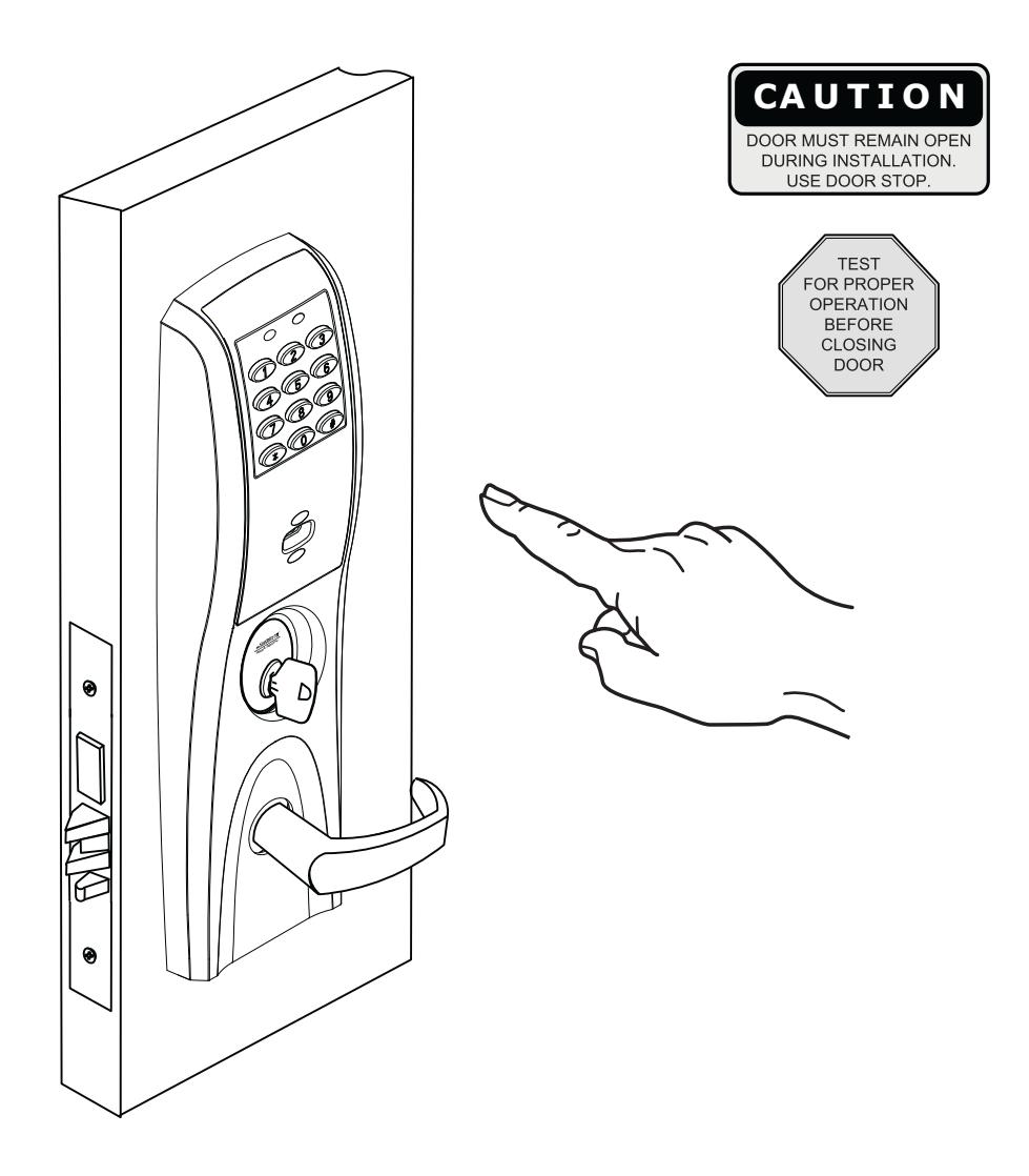
Corbin Russwin Access 800 ML20800 TCWI1, TCIP1 Installation Instructions_FM335
Open the original PDF document
View PDFAccess 800°
Installation Instructions For ML20800 TCWI1/TCIP1 Series Mortise Lockset
FM335 10/18

In U.S.: Corbin Russwin, Inc. 225 Episcopal Road Berlin, CT 06037 USA www.corbinrusswin.com
In Canada: ASSA ABLOY Door Security Solutions Canada 160 Four Valley Drive Vaughan, Ontario, Canada L4K4T9 www.assaablov.ca
Attention Installer
Please read these instructions carefully to prevent missing important steps.
Please Note: Improper installation may result in damage to the lock and void the factory warranty.
Important: The accuracy of the door preparation is critical for proper functioning and security of this lock.
Misalignment can cause premature wear and a lessening of security.
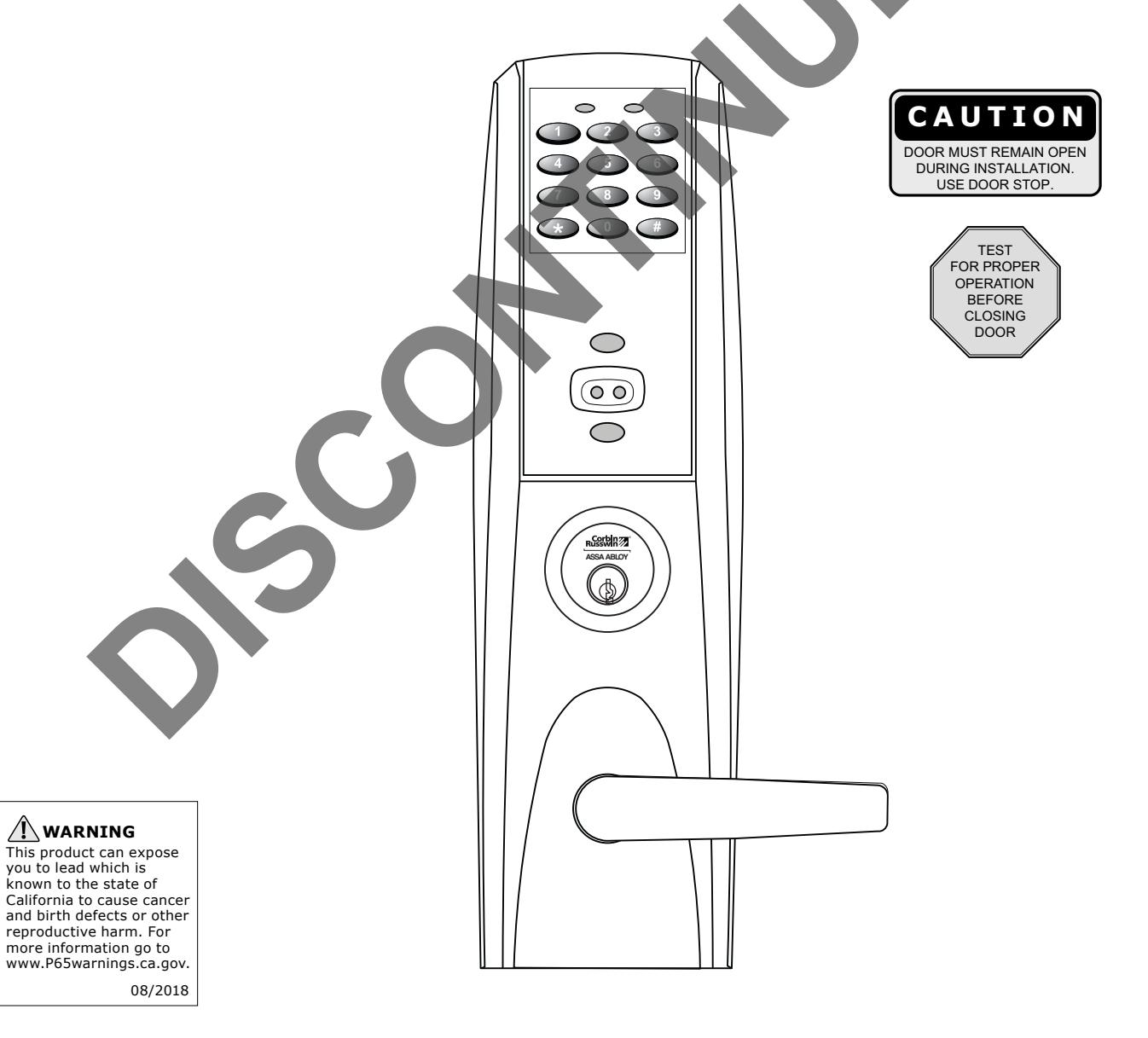
For installation assistance contact Corbin Russwin Inc., at 1-800-810-WIRE (9473)


Table of Contents
| 1) Warning | 3 |
|---|---|
| 2) General Description/Specifications/Features | 4 |
| 3) ML20800 Series Product Illustration | 5 |
| 4) Installation Instructions | 6-12 |
| 5) TCIP1 (PoE) Wiring Instructions | 13-15 |
| 6) Hard Wiring Instructions | 16-17 |
| 6.1) Important | 16 |
| 6.2) Installation Notes | 16 |
| 6.3) Electrolynx® Connector System Notes | 16 |
| 6.4) Hard Powered Connections | 17 |
| 7) Operational Check | 18 |
1) Warning
Changes or modifications to this unit not expressly approved by the party responsible for compliance could void the user's authority to operate the equipment.
This device complies with Part 15 of the FCC Rules. Operation is subject to the following two conditions: (1) this device may not cause harmful interference, and (2) this device must accept any interference received, including interference that may cause undesired operation.
Note: This equipment has been tested and found to comply with the limits for a Class B digital device, pursuant to Part 15 of the FCC Rules. These limits are designed to provide reasonable protection against harmful interference in a residential installation. This equipment generates, uses and can radiate radio frequency energy and if not installed and used in accordance with the instructions, may cause harmful interference to radio communications. However, there is no guarantee that the interference will not occur in a particular installation. If this equipment does cause harmful interference to radio or television reception, which can be determined by turning the equipment off and on, the user is encouraged to try to correct the interference by one or more of the following measures:
- Reorient or relocate the receiving antenna
- Increase the separation between the equipment and receiver
- Connect the equipment into an outlet on a circuit different from that to which the receiver is connected
- Consult the dealer or an experienced TV technician for help
This Class B digital apparatus complies with Canadian ICES-003.
▲ Warning: To comply with "Fire Listed" doors, only alkaline batteries must be used.

2) General Descriptions/ Specifications/ Features
General Description
The Corbin Russwin Access 800 WI1 WiFi lock uses IEEE 802.11 b/g WiFi infrastructure to connect to the access control system, making it ideal for adding access control to areas of a building that would be too difficult or costly to wire. With no wires to run, it significantly reduces hardware and labor costs.
The Access 800 IP1 PoE lock uses a single Ethernet cable for both power and data, eliminating the need for any additional power supply or electrical wiring. It uses existing IEEE 802.3af PoE infrastructure to streamline the installation process, reduce costs, enable real-time communication, and minimize power consumption.
Specifications
- Latch Stainless Steel
- Deadbolt Stainless Steel
- Auxiliary Latch Stainless Steel, non handed
- Handing Easily field reversible without disassembling the lock body
- Case 12 gauge heavy duty wrought steel
- UL Listed (3 hr.)
- Locking side controlled by any combination of keypad, prox card or cylinder override
- Non-locking side lever retracts latch and deadbolt
- Locks furnished for 1-3/4" doors. Can be furnished for other door sizes upon request. (Consult Factory)
Features
- Intelligent, integrated ANSI/BHMA Grade 1 lockset, available in cylindrical lock, mortise lock, and exit device configurations, offers the highest degree of physical security available in access control locks
- Local decision making ensures operation regardless of network status
- Built-in door status monitoring and real-time, configurable alarm notifications
- Supports 2,400 users and 10,000 event audit trail
- Supports HID® 125 kHz prox or 13.56 MHz iCLASS® credentials (26 39 bit); supports CSN reads for other common 13.56 MHz cards, including MiFare, DesFire, and Felica
- Available with a keypad option for two-factor authentication
- Weatherseal gaskets and conduit included for use on exterior doors
- WiFi version (TCWI1) uses 6 AA alkaline batteries or remote electrical power
- PoE version (TCIP1) is a Class 2 device, as defined by IEEE 802.3af, requiring a maximum of 7 watts

3) ML20800 Series Product Illustration

Verify hand and bevel of door. Illustrations shown are as viewed from the outside or secure side of opening. 1
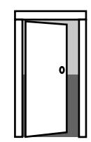
Left Hand Hinges Left. Open Inward. "LH"
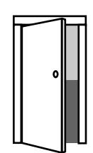
Left Hand Reverse Bevel Hinges Left. Open Outward "LHR"
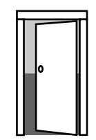
Right Hand Hinges Right. Open Inward. "RH"
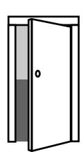
Right Hand Reverse Bevel Hinges Right. Open Outward "RHR"
2 Prep door according to supplied door marker.

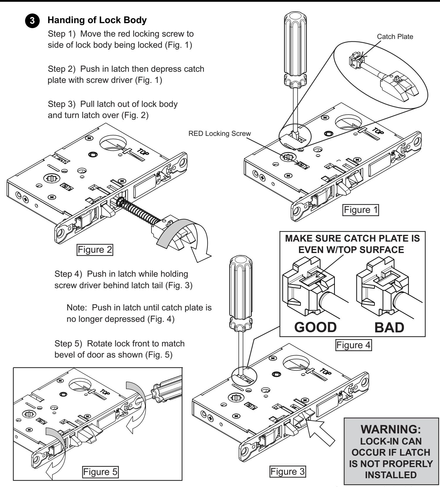

4 Lock Assembly Instructions
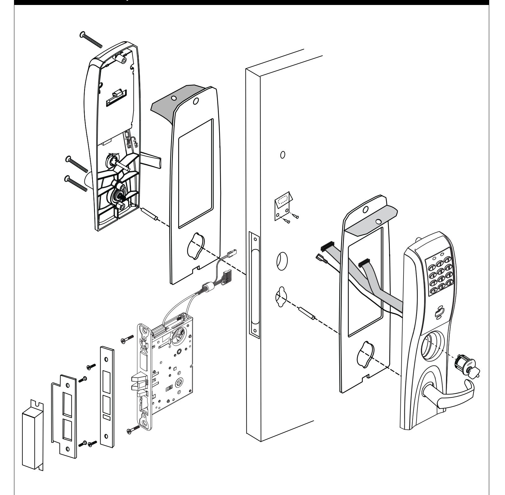
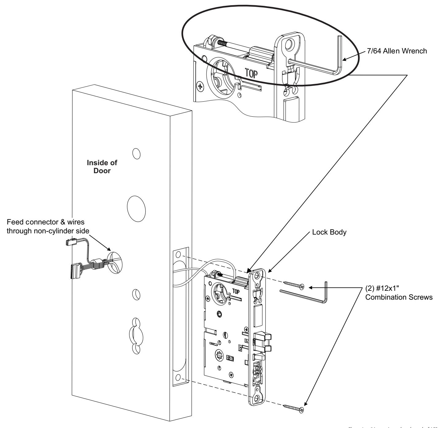
Align bevel accordingly. Engage 7/64 Allen wrench onto cap screw required for Step 5:3 on page 9. Feed connector and wires through 1" (25) dia. wire access hole. Insert lock body into mortise cutout in door and hold loosely in place with (2) #12x1" lock body screws.

5 Installation of Outside Escutcheon
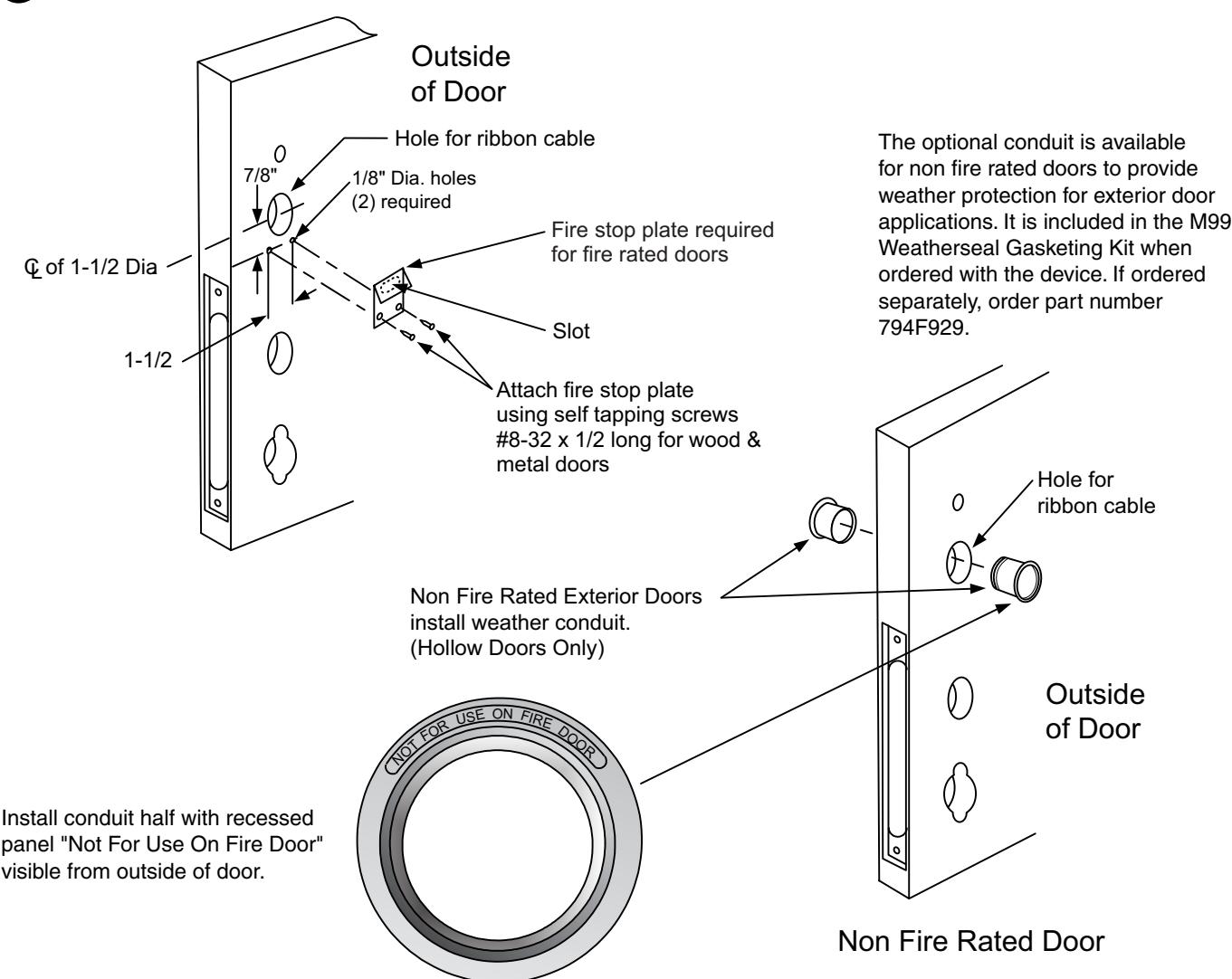
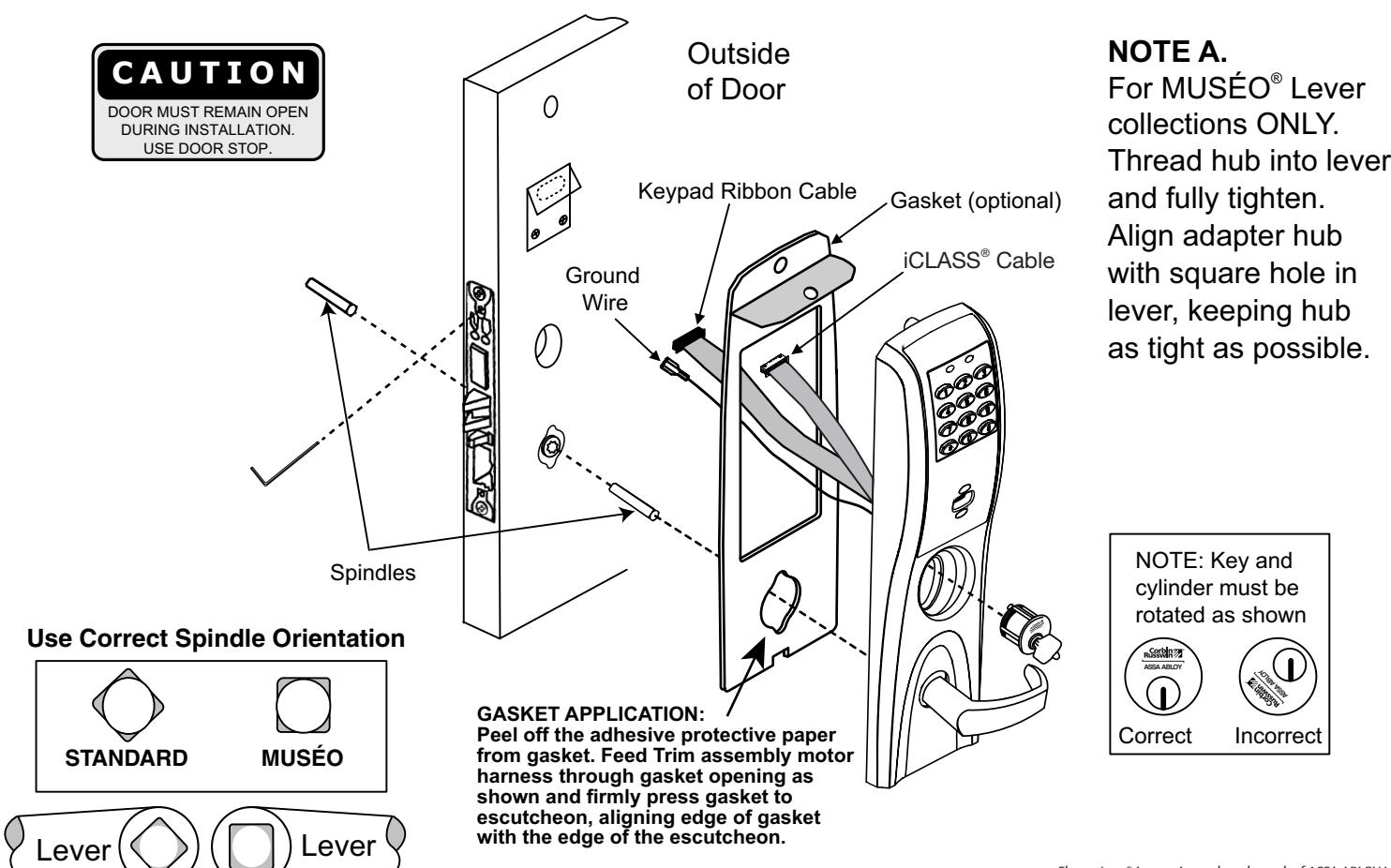
- 1. For exterior applications, an optional M99 Weatherseal Gasketing Kit can be ordered when a device is ordered. This kit includes gaskets and a conduit. When ordering the kit separately, order part number 794F929. The gaskets may be used as a seal between the escutcheon and the door surfaces.
- 2A. For fire rated doors, feed ribbon cable connector and ground wire from outside escutcheon through the fire stop plate.
- 2B. For non-fire rated doors, feed ribbon cable connector and ground wire from outside escutcheon through weather seal gasket (if used), then conduit sleeve in door (not shown).
- 3. With outside lever horizontal, insert mounting posts into the door. Make certain the lever spindle is properly engaged in lock. (see diagram and Note A. below) Screw cylinder into mortise lock, ensuring the cylinder orientation is in the correct position (see diagram below) . Using the 7/64 allen wrench provided, hand tighten (5-10 in. lbs.) the cap screw to prevent unscrewing of the cylinder. Turn the key to make certain that the locking mechanism (latch, deadbolt, key) functions correctly. Tighten (2) #12 x 1" lock body screws. Remove allen wrench.

6 Installation of Inside Escutcheon
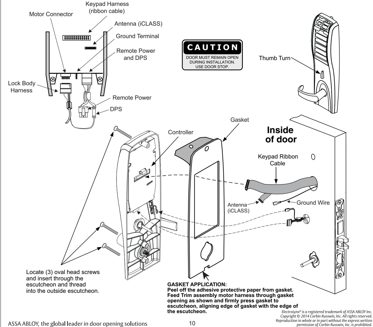
NOTE: Connectors go on only one way. Do not offset connector and be sure they are completely seated.
- 1. Remove black battery cover from the escutcheon with high security T20 Trox bit provided.
- 2. Connect ground wire to ground terminal. Keypad ribbon cable connector to controller, iCLASS antenna (M812 & M813 only), lock body harness to motor connector, DPS connector on lock body harness to remote power and DPS harness, and connect remote power if applicable.
- 3. Align thumb turn to the vertical position.
- 4. Push excess keypad ribbon cable into the ribbon cable hole.

6 Installation of Inside Escutcheon (continued)
- 1. Turn inside lever to the horizontal position and rotate the thumb turn to the vertical position. Slide onto spindle halfway. With inside escutcheon resting on spindle, be certain that all keypad ribbon cable will remain inside ribbon cable hole, and that ground wire will not get pinched once escutcheon is mounted. Escutcheon will not fit flush on door otherwise.
- 2. Insert 3 #10-24 screws through inside escutcheon and thread loosely into outside escutcheon. Check operation of both inside and outside levers and make sure the thumb turn and key still operate the latch and deadbolt correctly. If lock function is satisfactory, fully tighten the bottom two screws. Check operation of both levers again. If levers move freely, tighten top screw. If levers do not move freely, loosen bottom screws and realign the escutcheons until proper operation is obtained.
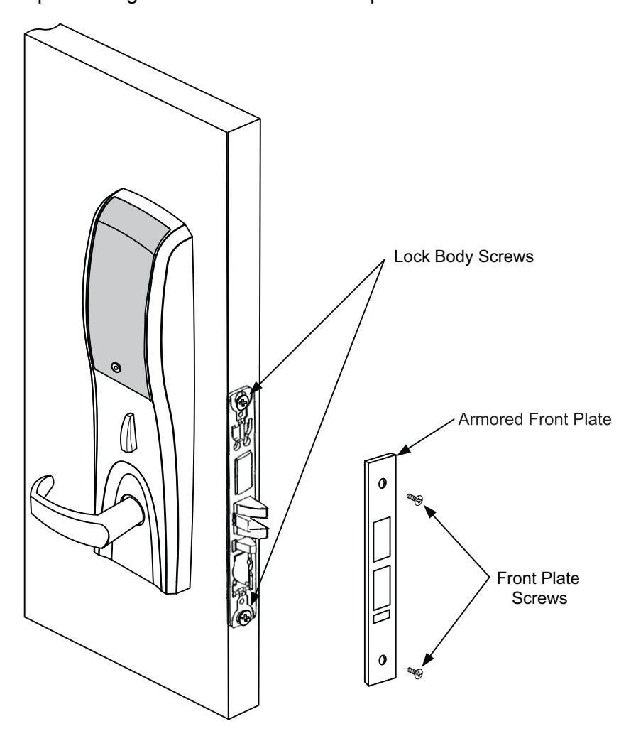
7 Installation of Armored Front Plate
1. Install armored front plate using two #8-32 x 1/4" screws provided.

-
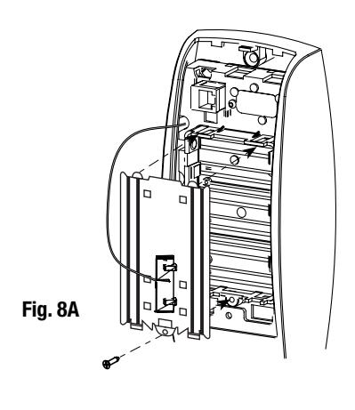
8 Installation (or Replacement) of Batteries, Battery Keeper & Cover (WI1 only)
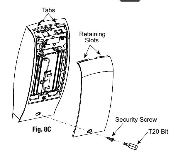
- 1. To install the batteries, first remove the battery cover using the T20 bit provided. (Fig. 8C)
- 2. Unscrew the bottom screw of the battery keeper and remove the battery keeper, being careful not to break the tabs at top holding it in place. (Fig 8A)
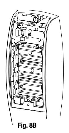
- 3. Place (6) "AA" batteries in the compartment, being careful to align polarity properly (Fig. 8B)
- 4. Replace battery keeper being careful to engage tabs at top to hold it in place. (Fig 8A)
- 5. Attach battery cover to inside escutcheon making sure to line up tabs with retaining slots in battery cover.
- 6. Secure with the security screw and T20 bit. (Fig 8C)

5) IP1 (PoE) Installation Wiring
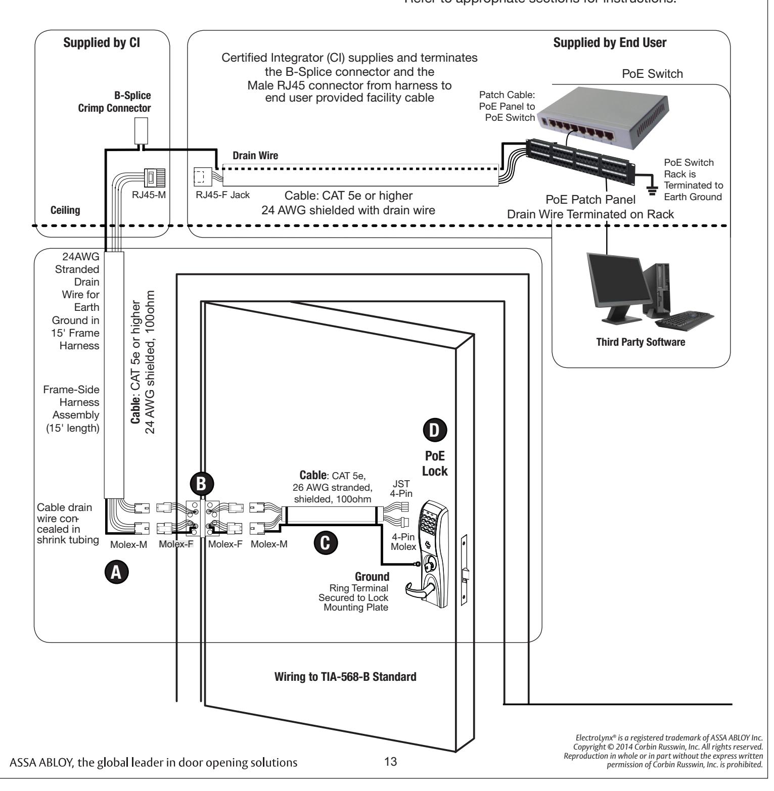
- PoE Frame harness assembly (From McKinney)
- PoE data hinge (U.S. Patent No. 7,824,200) (From McKinney)
- PoE Door harness* (From McKinney)
- Access 700 PIP1 (PoE Lock) * Order of installation may vary. Refer to appropriate sections for instructions.

5) IP1 (PoE) Installation Wiring (Continued)
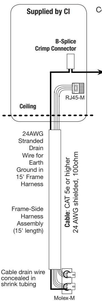
A Frame Harness Installation
B
concealed in shrink tubing
Components and wire harness supplied by McKinney: Suggested installation.
Cut end / ceiling-side PoE harness: TIA-568-B Standard Wiring
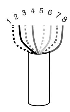
| Pair Number | Wire | PIN | |
|---|---|---|---|
| 1 | White/Blue | White/Blue | 5 |
| Blue | 4 | ||
| 2 | White/Orange | White/Orange | 1 |
| Orange | 2 | ||
| 3 | White/Green | White/Green | 3 |
| Green | 6 | ||
| 4 | White/Brown | White/Brown | 7 |
| Brown | 8 | ||
Do not confuse pair numbers with pin numbers. A pair number is used for reference only (eg: 10BaseT Ethernet uses pairs 2 & 3). The pin numbers indicate actual physical locations on the plug and jack.
Hinge side of PoE harness:
- 1. Feed cut end of harness into hole on hinge-side through single access hole.
- 2. Push one of the connectors back through hole and feed into separate access hole.
Each of the hinge-side harness connectors should end up threaded through a different access hole and matched to the same size pin connector from the door harness:
- 4-pin male Molex connector.
- 6-pin male Molex connector with ground wire.
Notes:
- Connectors only go on one way. They cannot be plugged to incorrect position.
- Do not force and do not offset connectors.
- Be sure they are completely seated (flush).
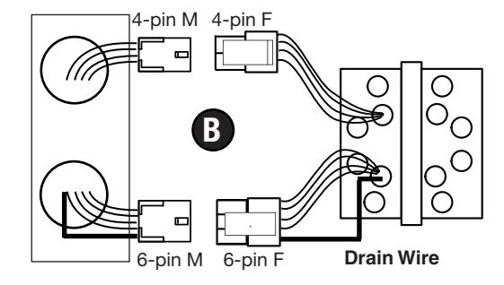
Frame PoE Hinge (Patent Pending)

5) IP1 (PoE) Installation Wiring (Continued)
Hinge Installation B
Order of installation may vary. Refer to appropriate sections for instructions.
Hinge-side harness connectors:
- 4-pin male Molex connector
- 6-pin male Molex connector with ground wire
Lock-side harness connectors:
- Ring terminal
-
(2) 4-pin connectors:
- 4-pin Molex connector
- 4-pin connector
Notes:
- Connectors go on only one way. They cannot be plugged to incorrect position.
- Do not force and do not offset connectors.
- Be sure they are completely seated (flush).


C Door Harness Installaion
Order of installation may vary. Refer to appropriate sections for instructions.
- 1. Prop door open.
- 2. Tape the two lock-side 4-pin connectors to the ring terminal.
- 3. Using the ring terminal, carefully fish the assembly through the door channel to the lock.
-
4. Remove tape from ring terminal and door harness connectors. Hinge-side harness connectors:
- 4-pin male Molex connector
- 6-pin male Molex connector with ground wire
Lock-side harness connectors:
- Ring terminal
-
(2) 4-pin connectors:
- 4-pin Molex connector
- 4-pin connector
Notes:
- Connectors go on only one way. They cannot be plugged to incorrect position.
- Do not force and do not offset connectors.
- Be sure they are completely seated (flush).
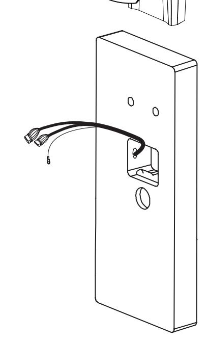
Ring
to Lock Mounting Plate

6) ML20800 Hardwiring Instructions
6.1) Important
- 1. Caution: Disconnect all input power before beginning installation to prevent electrical shock and equipment damage.
- 2. Installer must be a trained, experienced service person.
- 3. All wiring must comply with applicable local electrical codes, ordinances and regulations.
6.2) Installation Notes
- ® 1. With new applications, an ElectroLynx door harness with 8 and 4 pin connectors may be preinstalled inside door by ASSA ABLOY door manufacturer when specified during ordering process.
- ® 2. Wiring to pigtail harness is per facility wiring requirement. ElectroLynx connector terminations and wire colors all match.
- ® 3. If door does not have an ElectroLynx type door harness, cut connectors off product and hard wire, or consult factory for appropriate mating harness.
® 6.3) ElectroLynx Connector System Notes:
The system is designed to be installation friendly with pluggable connectors from the electric hinge through the door to the rail. The only wiring required is to the loose wires on the pigtail harness assembly on the frame side of the electric hinge.
IMPORTANT:
The plug and receptacle connectors are designed to mate and lock together as shown in the figure. Plug the connectors into each other with the locking mechanism aligned as indicated. Do NOT Force connectors on any other way.
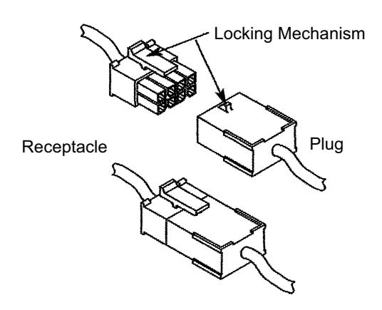

As part of their promise to provide innovative, fast and effective high security solutions to their customers, certain ASSA ABLOY Group brands offer ® ElectroLynx , a universal quick-connect system that simplifies the electrification of the door opening.

6) ML20800 Hardwiring Instructions
6.4) Hard Powered Connections
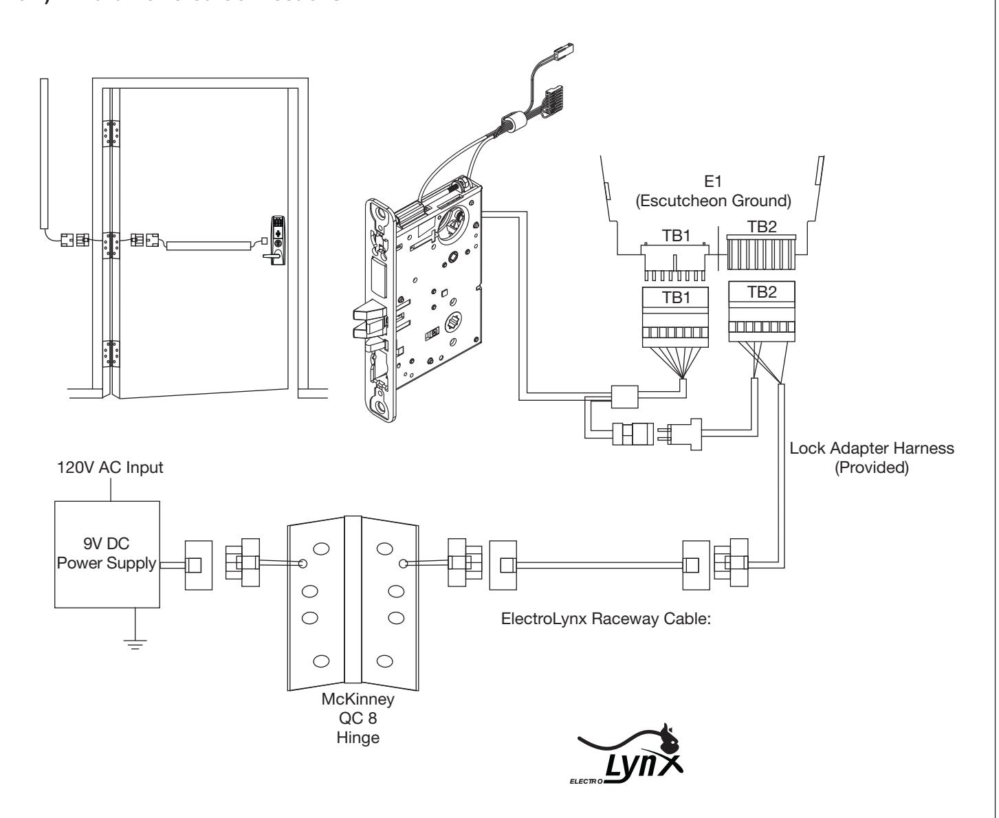
END OF INSTALLATION INSTRUCTIONS

7) Operational Check
Lock operational check for devices with cylinders:
- 1. Insert key into cylinder and rotate. (There should be no friction against lock case, wire harness or any other obstructions.)
- 2. The key will retract the latch, key should rotate freely. If the deadbolt is thrown, the key will first retract the deadbolt and then the latch. Inside lever retracts latch and deadbolt, if provided.
- 3. Use proximity card or PIN code set up with lock configuration tool. This should unlock outside lever and allow latch to be retracted. Please see Network & Lock Configuration Tool user manual (WFMN1) for more information.