Corbin Russwin Access 800 9800 Series Installation Instructions_FM225
Open the original PDF document
View PDF

ASSA ABLOY
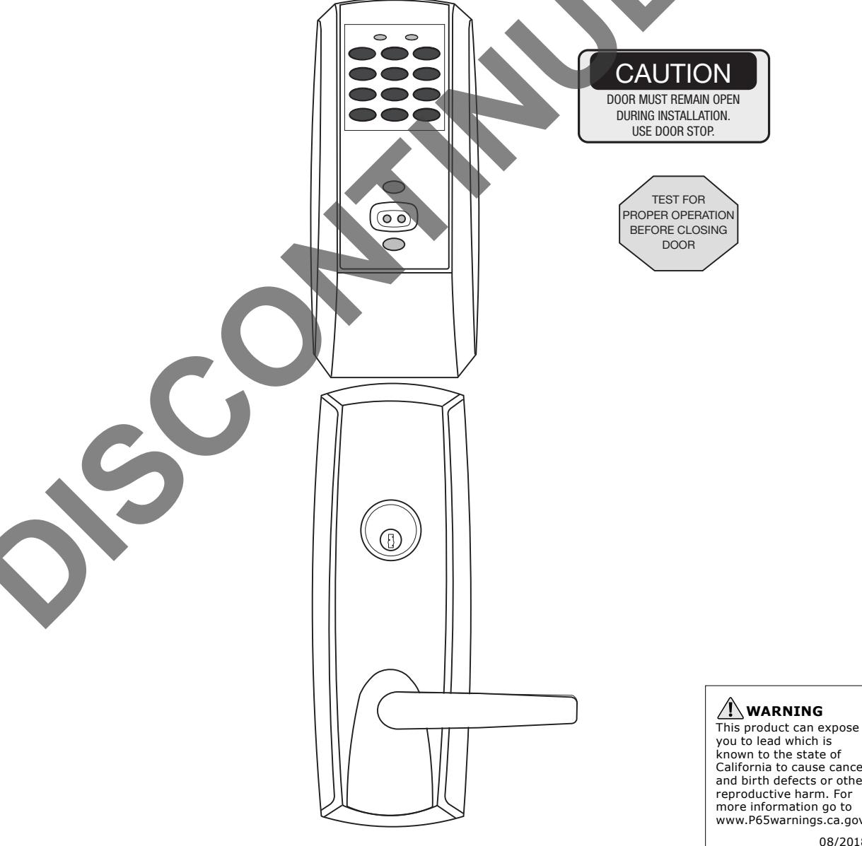
Installation Instructions For 9800 TCAC2 Series Trim by ED5200 (S) (A) and 9M800 TCAC2 Series Trim by ED5600 (A) with Rim, SecureBolt™ and Mortise Exit Devices
FM225 10/18
Attention Installer
Please read these instructions carefully to prevent missing important steps.
Please Note: Improper installations may result in damage to the lock and void the factory warranty.
Important: The accuracy of the door preparation is critical for proper functioning and security of this lock.
Misalignment can cause premature wear and a lessening of security.
For installation assistance contact Corbin Russwin Inc., at 1-800-810-WIRE (9473)
Copyright © 2018 Corbin Russwin, Inc., an ASSA ABLOY Group company. All rights reserved. Reproduction in whole or in part without the express written permission of Corbin Russwin, Inc. is prohibited.
known to the state of
California to cause cancer and birth defects or other reproductive harm. For more information go to www.P65warnings.ca.gov.
08/2018
ASSA ABLOY, the global leader in door opening solutions
Table of Contents
| 1 Warning | 3 |
|---|---|
|
2 General Description, Specifications and Features
|
4 |
|
3 9800 TCAC2 Series Trim Product Illustration (Rim and SecureBolt™)
|
5 |
| 4 Installation Instructions (Rim and SecureBolt) | 6 |
|
5 9M800 TCAC2 Series Trim Product Illustration (Mortise)
|
10 |
|
6 Installation Instructions (Mortise)
|
11 |
| 7 Battery Installation (Rim, SecureBolt, and Mortise) | 16 |
| 8 Installation of RF Technology Lock(Rim, SecureBolt, and Mortise) | 17 |
| 9 Operational Check (Rim, SecureBolt, and Mortise) | 18 |
| 10 9800 TCAC2 Wiring Instructions for Rim, SecureBolt™ and Mortise | 19 |
1 Warning

This device complies with Part 15 of the FCC Rules. Operation is subject to the following two conditions: (1) this device may not cause harmful interference, and (2) this device must accept any interference received, including interference that may cause undesired operation.
Note: This equipment has been tested and found to comply with the limits for a Class B digital device, pursuant to Part 15 of the FCC Rules. These limits are designed to provide reasonable protection against harmful interference in a residential installation.
This equipment generates, uses and can radiate radio frequency energy and if not installed and used in accordance with the instructions, may cause harmful interference to radio communications. However, there is no guarantee that the interference will not occur in a particular installation. If this equipment does cause harmful interference to radio or television reception, which can be determined by turning the equipment off and on, the user is encouraged to try to correct the interference by one or more of the following measures:
- Reorient or relocate the receiving antenna
- Increase the separation between the equipment and receiver
- Connect the equipment into an outlet on a circuit different from that to which the receiver is connected
- Consult the dealer or an experienced technician for help
Contains FCC ID: U4A-SCSEHF Contains IC: 6982A-SCSEHF
The term "IC:" before the radio certification number only signifies that Industry Canada technical specifications were met. This Class B digital apparatus meets all requirements of the Canadian Interference Causing Equipment Regulations. Operation is subject to the following two conditions: (1) this device may not cause harmful interference, and (2) this device must accept any interference received, including interference that may cause undesired operation.
Cet appareillage numérique de la classe B répond à toutes les exigences de l'interférence canadienne causant des règlements d'équipement. L'opération est sujette aux deux conditions suivantes: (1) ce dispositif peut ne pas causer l'interférence nocive, et (2) ce dispositif doit accepter n'importe quelle interférence reçue, y compris l'interférence qui peut causer l'opération peu désirée.
Any retrofit or other field modification to a fire rated opening can potentially impact the fire rating of the opening, and SARGENT Manufacturing makes no representations or warranties concerning what such impact may be in any specific situation. When retrofitting any portion of an existing fire rated opening, or specifying and installing a new fire-rated opening, please consult with a code specialist or local code official (Authority Having Jurisdiction) to ensure compliance with all applicable codes and ratings.
Installation Instructions For 9800 TWCI1 & TCPIP1 Series Trim by ED5000 Series with SecureBolt™ and Rim Exit Devices

2 General Description / Specifications / Features
The Rim, SecureBolt™ and Mortise Exit Devices are designed for areas which require stand alone authorized entry. It is a self -contained microprocessor-controlled keypad with non-volatile memory. The keypad will hold a total of 100(M800)/2000 (M801, M802, M803, M804, M805, M806) different user codes. User codes "01", "02" and "03" are utilized for Master, Emergency and Supervisory Codes respectively. This product is operated by six (6) "AA" alkaline batteries. Corbin Russwin Inc. exit devices and trim are designed with quality components to provide high security, performance and durability.
Items Supplied with Exit Device
- Outside Escutcheon with Keypad
- Outside Motorized Trim Assembly
- Exit Device
- Inside Escutcheon with Circuit Board and Battery Pack
- 6 "AA" alkaline batteries
- Screw Pack
Specifications
- Latch 3/4" throw, anti-friction, stainless steel
- Outside motor driven lever controlled by keypad
- Push bar retracts latch from inside
- Fire stop provided for fire rated doors
- Exit devices furnished for 1-3/4" 2 1/4" doors
- UL Listed
Features
- Low battery alert 4 chirps after code entry
- External remote "request to enter" connector
- Master, Emergency or Supervisory code will unlock door when (low) battery has expired
- Programming can be done at the keypad (Except M802 & M805) or with a PDA using Accessware™ with Access HH application software.
Items included with ED5200 (S) (A) Rim or SecureBolt Exit Device by 9800 TCAC2 ED5600 (A) Series
• Rim cylinder for 9834
Items included with ED5600 (A) Series Mortise Exit Device by 9M800 TCAC2 Series Trim
- Mortise cylinder for 9M834
- Accepts all Corbin Russwin:
- Rim cylinders (9834 only)
- Mortise cylinders (9M834 only)
- Key allows lever to retract latch (9834 only)
- Key retracts latch (9M834 only)
- Available in all lever handle designs
- Entry of three wrong User Codes disables all codes for ten seconds. (Yellow LED on solid)
- Last 15 transactions can be output to portable printer via infrared link (M800 Only)
- Last 2000 (Except M800) transactions can be output to a PC via a PDA and Accessware

3 9800 TCAC2 Series Trim Product Illustration (Rim and SecureBolt™)
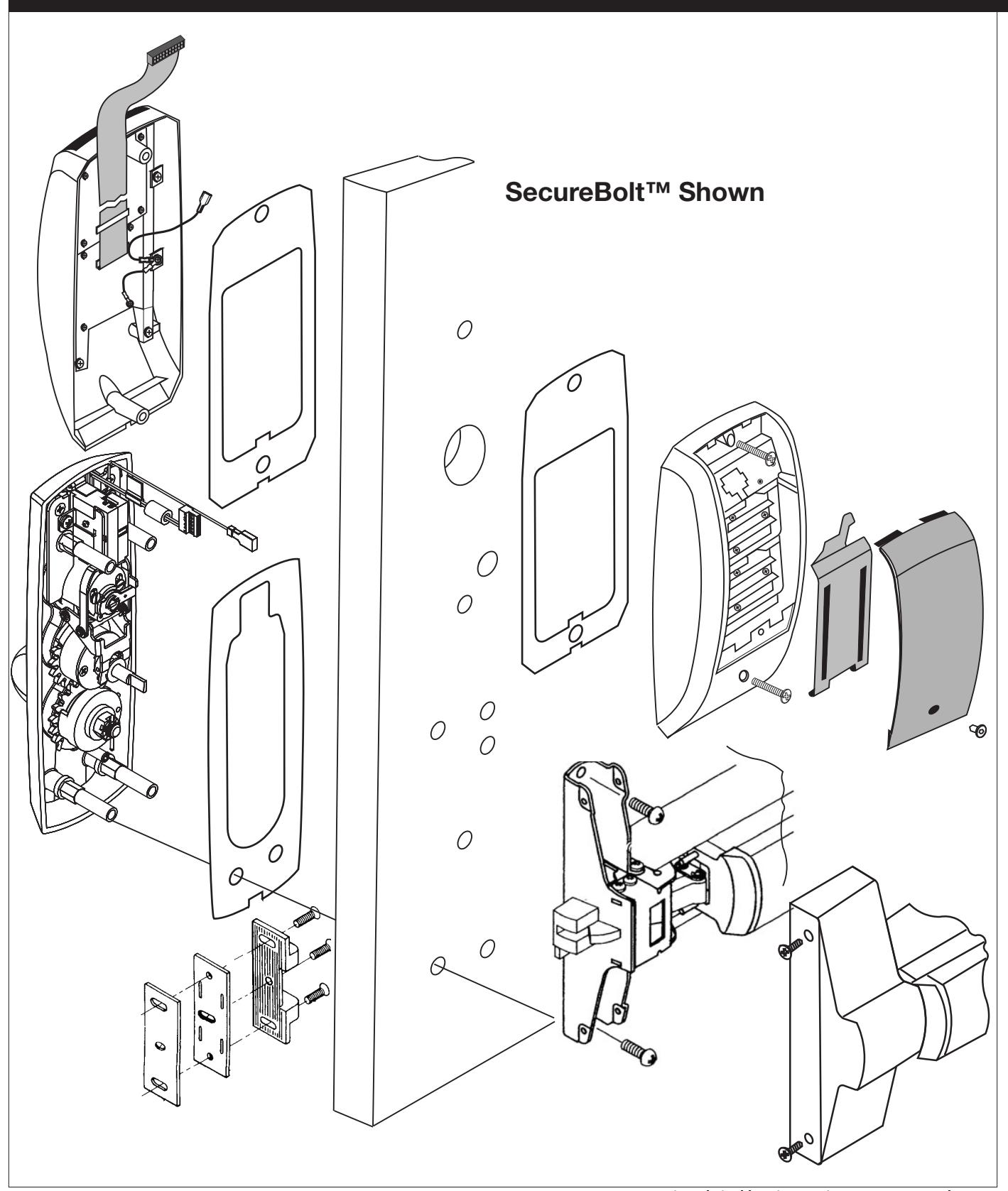

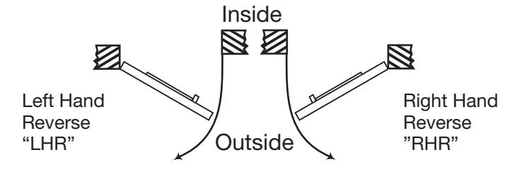
This device is not handed, however the Trim assembly is handed. Door should be fitted and hung. Verify box label for size of exit device, function and hand.
Prep door according to supplied Corbin Russwin Inc. door marker template.

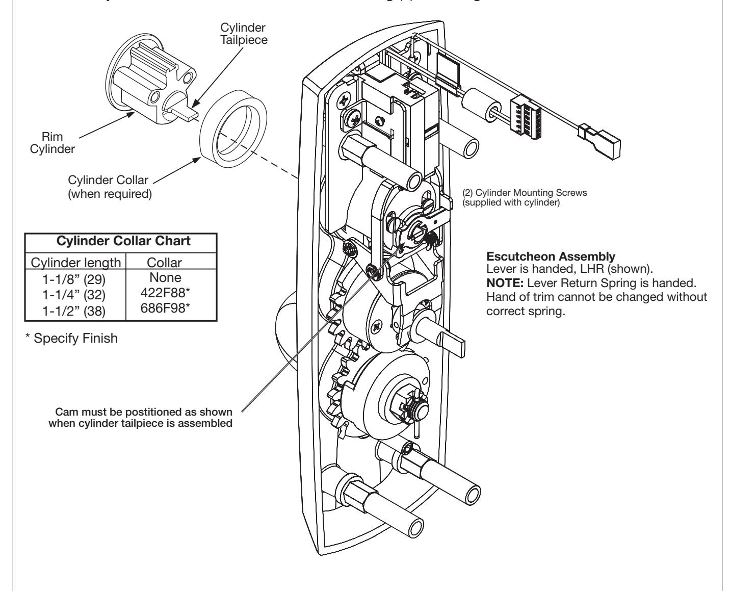
1. Check cylinder components.
NOTE: Cylinders longer than 1-1/8" (29mm) will require collars.
Refer to Cylinder Collar Chart below.
2. When required, cut cylinder tailpiece.
Correct length is 1/16" to 3/16" (2 to 5mm) beyond cylinder housing cam.
3. Assemble cylinder.
Insert cylinder housing prongs into matching notches of escutcheon.
Pass cylinder tailpiece thru cylinder collar (when required) and slot in cylinder housing cam.
Fasten cylinder in escutcheon recess or collar using (2) mounting screws.

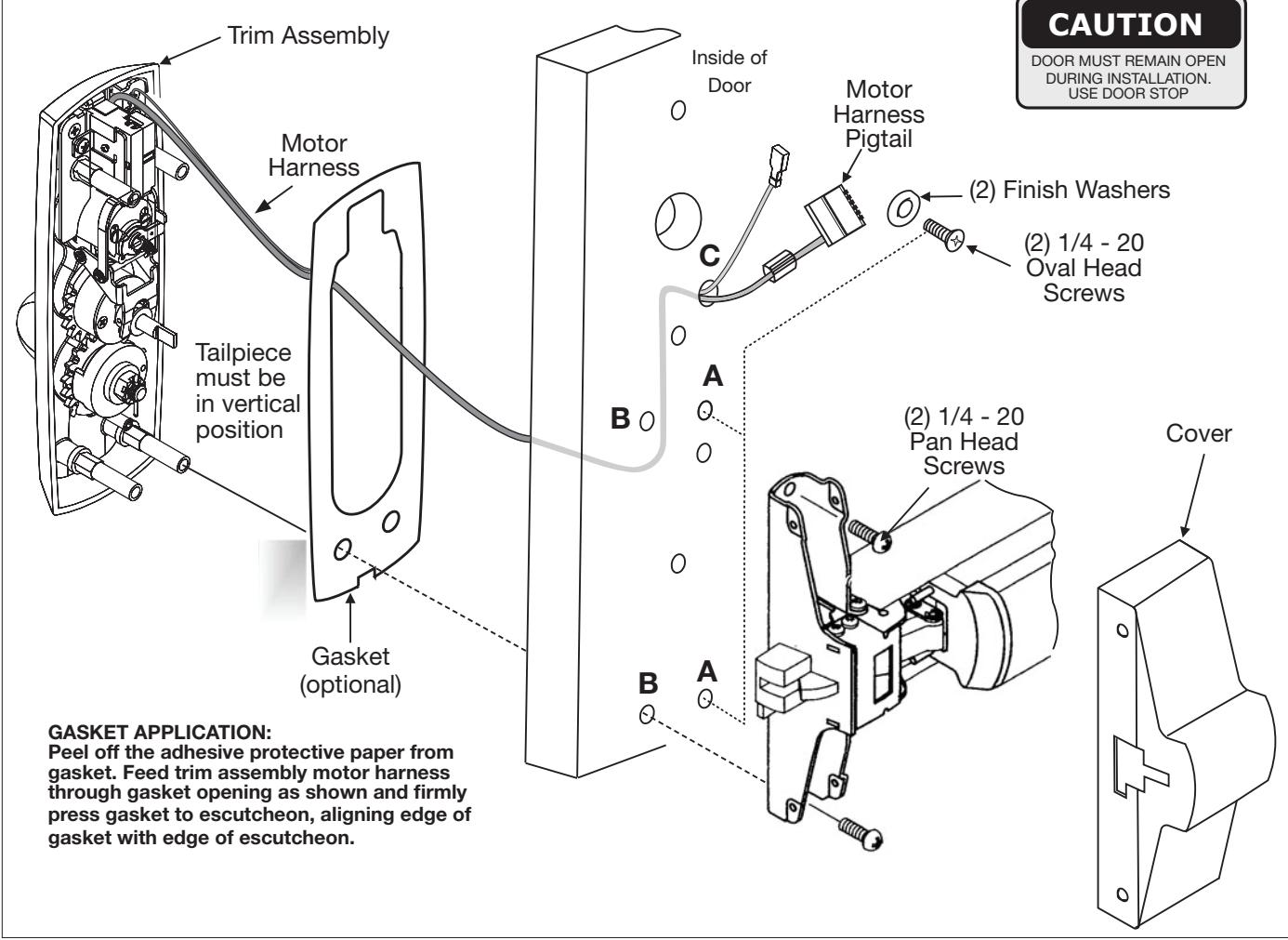
Outside Trim Assembly
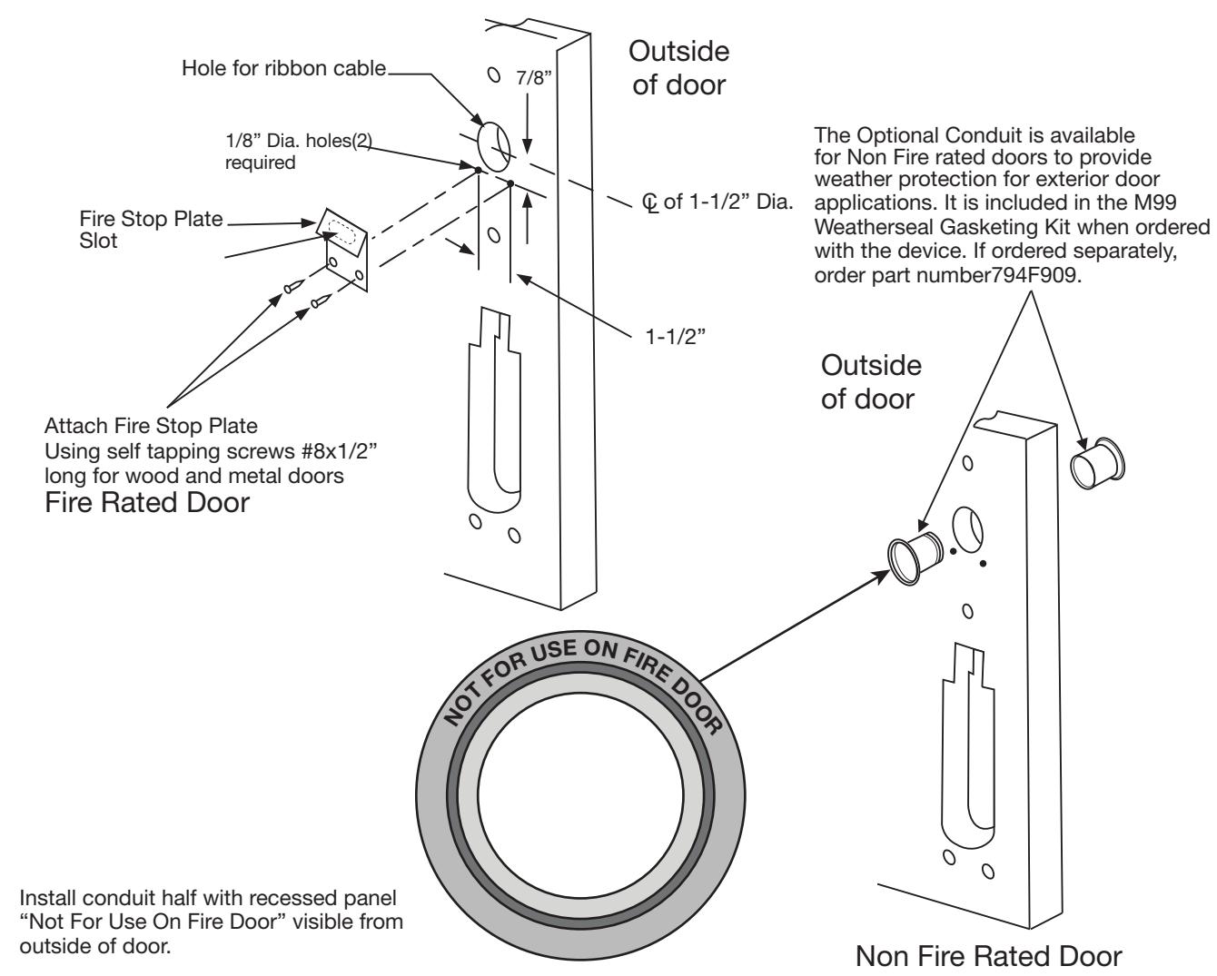
- 1. For exterior applications, an optional M99 Weatherseal Gasketing Kit can be ordered when a device is ordered. This kit includes gaskets and a conduit. When ordering the kit separately, order part number 794F909.
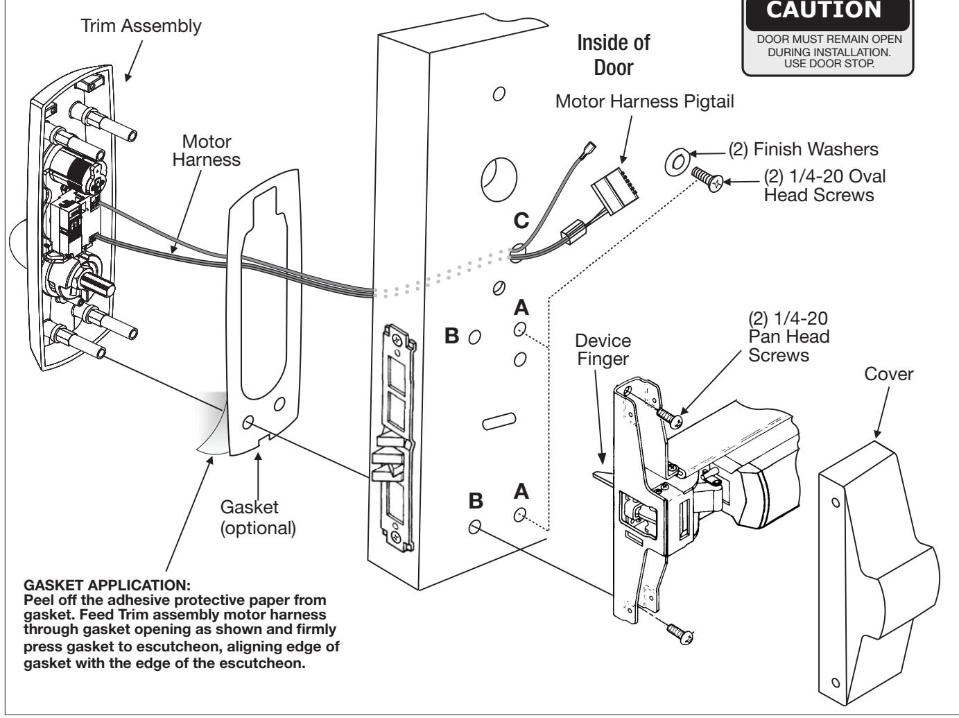
- 2. Route motor harness pigtail thru 1/2" diameter hole "C" on inside of door and out otherside through trim assembly prep. Connect to trim assem
- 3. Mount trim assembly to door pulling slack wire from motor harness pigtail towards deviceside of door. Be careful not to pinch harness wires.
- 4. When mounting trim, lift tailpiece to pass through hole on device side. Be sure tailpiece is in vertical position.
- 5. Fasten trim assembly to door through holes "A" using (2) 1/4 20 oval head screws and (2) finish washers. NOTE: Finger tight only!
Exit Device
- 1. Seat device against door being careful to align vertical trim tailpiece to engage with cross hole of device cam.
- 2. Fasten device to trim assembly through holes "B" using (2) 1/4 20 pan head screws.
- 3. Follow instructions packed with device to secure device to door. Tighten all screws.

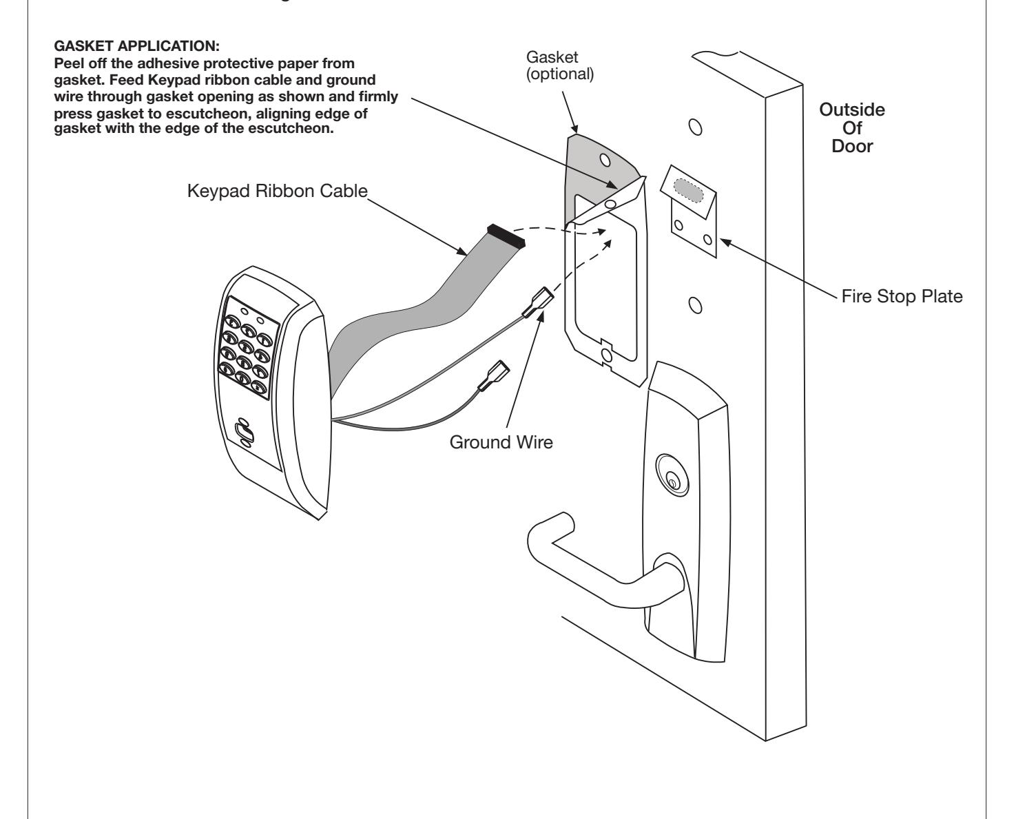
4.5 Installation of Outside Keypad Escutcheon
-
1. For exterior applications, an optional M99 Weatherseal Gasketing Kit can be ordered when a device is ordered. This kit includes gaskets and a conduit. When ordering the kit separately, order part number 794F909.
- The gaskets may be used as a seal between the escutcheonand the door surfaces.
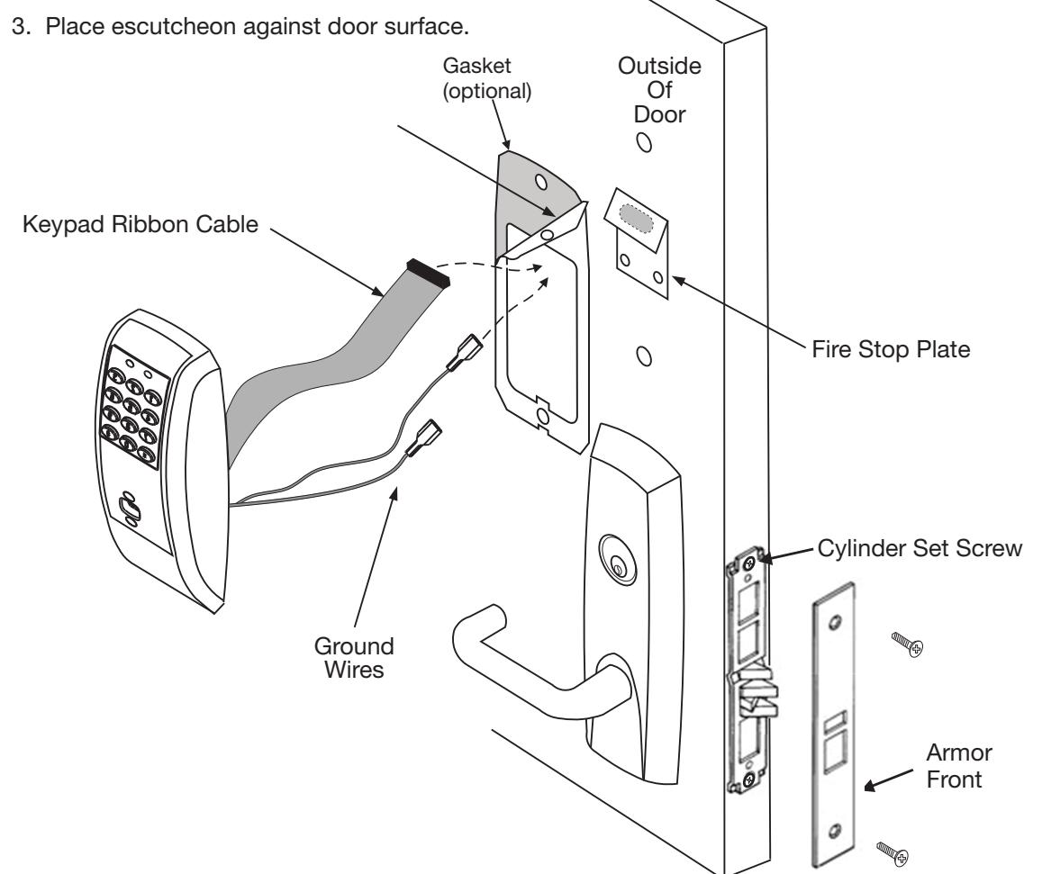
- 2a. For fire rated devices, feed keypad ribbon cable/connector and ground wire from outside of door through fire stop plate and hole in door.
- 2b. For non-fire rated exit devices, feed keypad ribbon cable/connector and ground wire through hole in door.
- 3.Place escutcheon against door surface.

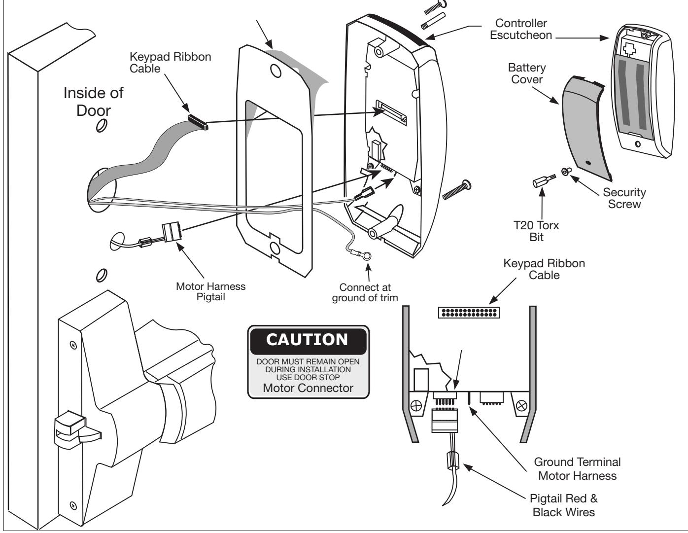
4.6 Installation of Inside Controller Escutcheon and Electrical Connections
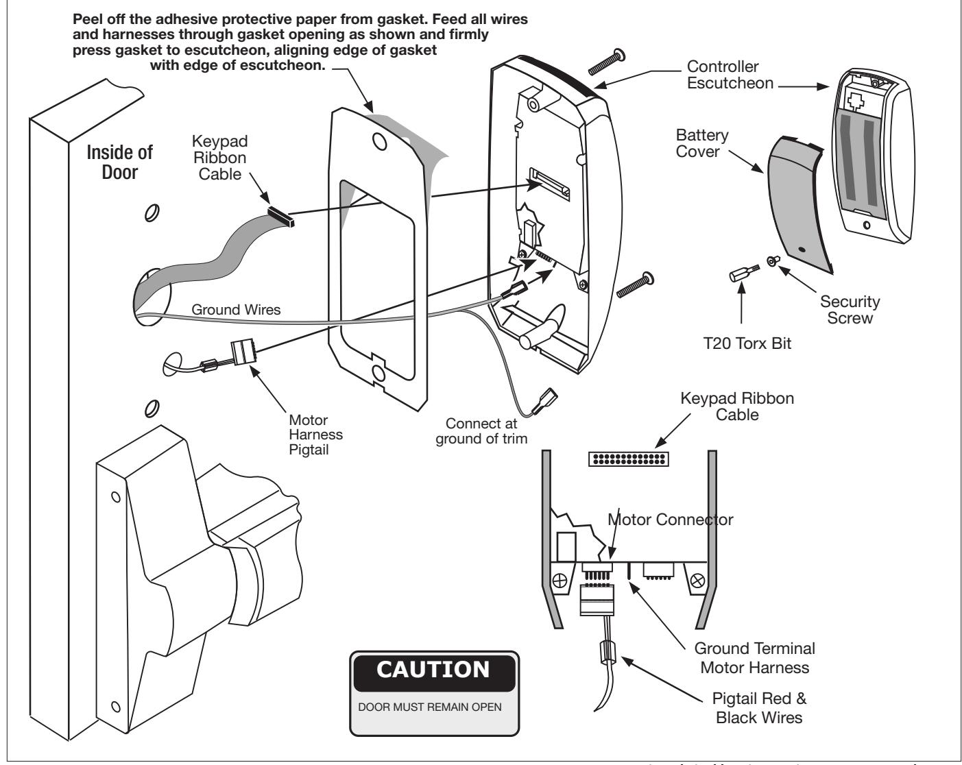
For exterior applications, an optional M99 Weatherseal Gasketing Kit can be ordered when a device is ordered. This kit includes gaskets and a conduit. When ordering the kit separately, order part number 794F909. The gaskets may be used as a seal between the escutcheon and the door surfaces.
- 1. Remove black battery cover from controller escutcheon with high security T20 Torx Bit (provided).
- 2. Connect ground wire to terminal, connect keypad ribbon cable and motor harness pigtail to controller.
- 3. Feed excess keypad ribbon cable and ground wire through inside door hole and into outside keypad escutcheon cavity, being careful not to pinch wires. Gather excess motor harness pigtail wire into lower cavity of inside controller escutcheon, being careful not to pinch wires.
NOTE: Connectors go on only one way, do not offset connector and be sure they are completely seated.
4. Insert (2) #10 x 24 screws through top and bottom of inside escutcheon and thread into outside escutcheon. Straighten escutcheons and tighten securely, being careful to avoid pinching wires.
For Battery Installation refer to Section 7 page 15.
NOTE: For RF Technology versions refer to Section 8 page 16 to install through-bolt screws.

5 9M800 TCAC2 Series Trim Product Illustration (Mortise)
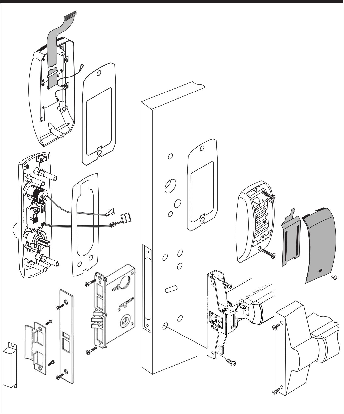

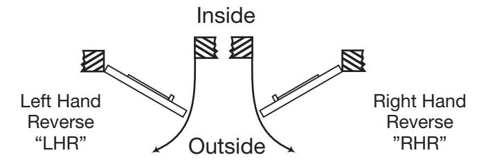
This device is handed because of the mortise lock and trim assembly being handed. Door should be fitted and hung. Verify box label for size of exit device, function and hand.
Prep door according to supplied Corbin Russwin Inc. door marker template.

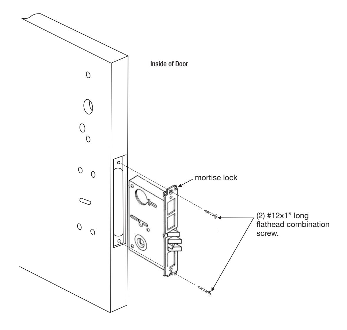
6.3 Install mortise lock
1. Slide mortise lock into door and loosely fasten with (2) flat head combination screws.

Outside Trim Assembly
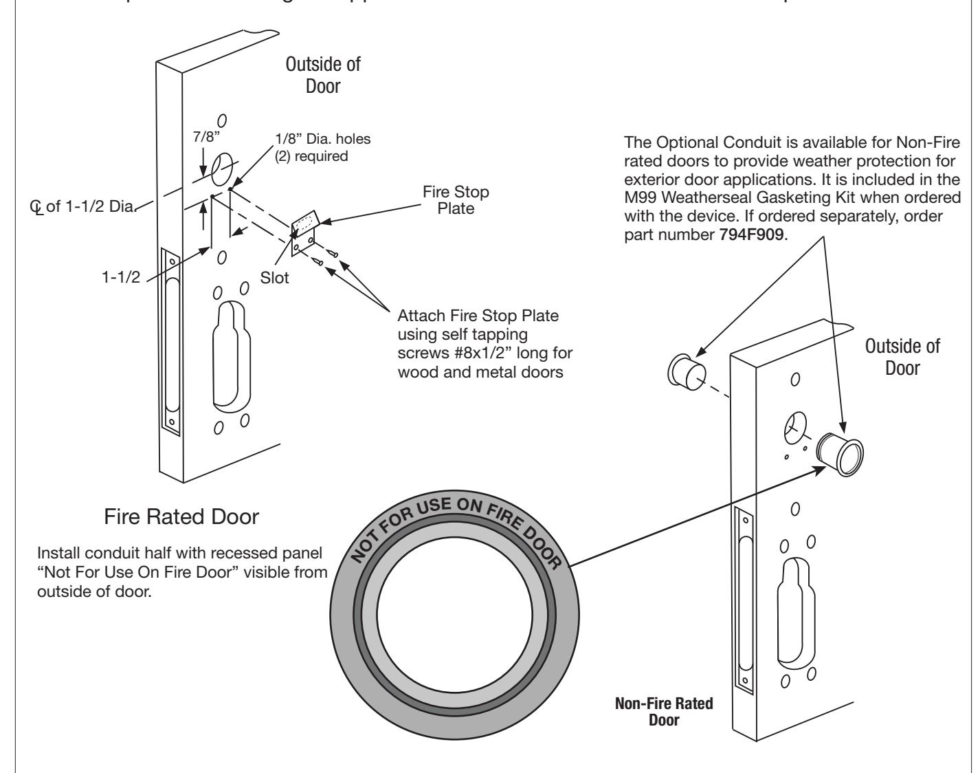
- 1. For exterior applications, an optional M99 Weatherseal Gasketing Kit can be ordered when a device is ordered. This kit includes gaskets and a conduit. When ordering the kit separately, order part number 794F909 .
- The gaskets may be used as a seal between the escutcheon and the door surfaces.
- 2. Route motor harness pigtail through 1/2" diameter hole "C" on inside of door and out other side through trim assembly prep. Connect to trim assembly motor harness.
- 3. Mount trim assembly to door pulling slack wire from motor harness and pigtail towards device side of door. Be careful not to pinch harness wires.
- 4. Fasten trim assembly to door through holes "A" using (2) 1/4-20 oval head screws and (2) finish washers. Finger tight only!
Exit Device
1. Seat device against door.
NOTE: Device finger must engage latch bolt lever thru slot in door and lock case/cover.
- 2. Fasten device to trim assembly through holes "B" using (2) 1/4-20 pan head screws.
- 3. Follow instructions packed with device to secure device to door.

Cylinder Installation
Note: For devices without cylinders, skip this section.
- 1. Back cylinder set screw out of mortise lock.
- 2. Insert cylinder through trim assembly and thread into mortise lock until cylinder is flush with escutcheon. Keyway should be vertical with plug toward lever.
- 3. Tighten cylinder set screw.
- 4. Assemble mortise lock armor front with (2) screws.
- 5. Tighten all screws for lock, trim assembly and exit device.
Outside Keypad Escutcheon
- 1. For exterior applications, an optional M99 Weatherseal Gasketing Kit can be ordered when a device is ordered. This kit includes gaskets and a conduit. When ordering the kit separately,order part number 794F909 . The gaskets may be used as a seal between the escutcheon and the door surfaces.
- 2a. For fire rated devices, feed keypad ribbon cable/connector and ground wire from outside of door through fire stop plate and hole in door.
2b. For non-fire rated exit devices, feed keypad ribbon cable/connector and ground wire through hole in door .

6.6 Installation of Inside Controller Escutcheon and Electrical Connections
- 1. For exterior applications, an optional M99 Weatherseal Gasketing Kit can be ordered when a device is ordered. This kit includes gaskets and a conduit. When ordering kit separately, order part number 794F909. The gaskets may be used as a seal between the escutcheon and the door surfaces.
- 2. Remove black battery cover from escutcheon with high security T20 Torx Bit (provided).
- 3. Connect ground wire to terminal, connect keypad ribbon and motor harness pigtail tomotor connector.
- 4. Feed excess keypad ribbon cable and ground wire through inside door hole and into outside escutcheon cavity, being careful not to pinch wires. Gather excess motor harness pigtail wire into lower cavity of inside escutcheon, being careful not to pinch wires.
- 5. Insert (2) #10 x 24 screws through top and bottom of inside escutcheon and thread into outside escutcheon. Straighten escutcheons and tighten securely, being careful to avoid pinching wires.
For Battery Installation refer to Section 7 page 16.
NOTE: For RF Technology versions refer to Section 8 page 17 to install through-bolt screws.
GASKET APPLICATION:

7 Battery Installation (Rim, SecureBolt™, and Mortise)
Battery Installation
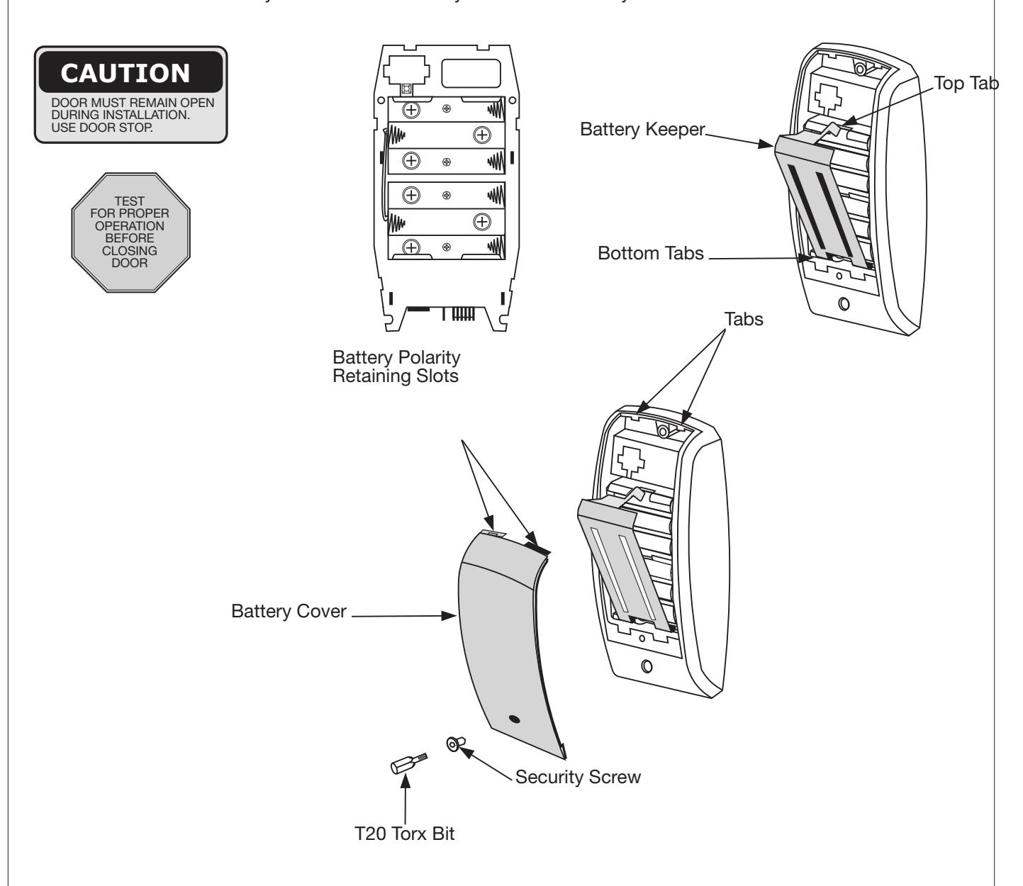
- 1. Remove battery keeper by lifting top tab and pulling away from the controller compartment.
-
NOTE: For RF Technology versions, refer to section 8 when removing or installing battery keeper
- 2. Install (6) AA Batteries into controller compartment being careful to align +/- polarity properly.
- 3. Install battery keeper by first inserting bottom tabs in bottom slots of controller. Lift the top tab over batteries and snap into position.
- 4. Attach battery cover to inside controller escutcheon making sure to line up tabs with retaining slots in battery cover. Fasten security screw with security T20 Torx bit.

8 Installation of RF Technology Lock (Rim, SecureBolt™, and Mortise)
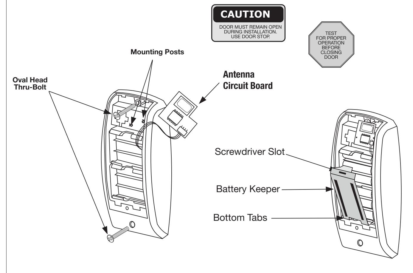
The RF Technology Lock (M804, M805, M806) is installed as described in Sections 4 and 6 with the following exceptions :
- Installation of the top through-bolt screw Removal procedure for the battery keeper
1. Installation of the top through-bolt screw:
The antenna board must be carefully moved to access the upper through-bolt screw. Care should be taken to prevent damage to the antenna retaining tabs during this process.
Press the two tabs away from the antenna board and lift the board off the mounting posts.
Insert the oval head through-bolt and secure the escutcheon in place. After tightening the to pthrough-bolt, replace the antenna board by placing it on the mounting posts and pressing into the retaining tabs .
2. Removal and Installation Procedure for Battery Keeper
To remove the battery keeper, a flat blade screwdriver or similar tool must be used.
Insert screwdriver into slot at top of battery keeper. Lift up and pull the top of the keeper away from the batteries .
To install the battery keeper, insert bottom tabs in bottom slots of controller, then press keeper over batteries and snap into position.

9 Operational Check (Rim, SecureBolt™ and Mortise)
- 1. For exit devices without cylinder override trims, go to Step 4 below.
-
2. For Rim and SecureBolt exit devices with 9834 Series cylinder override trims:
- a. Insert key into cylinder and rotate.
- b. While holding key in rotated position, operate outside lever to retract latch.
- c. Key should rotate freely and outside lever should retract latch.
-
3. For Mortise exit devices with 9M834 Series cylinder override trims:
- a. Insert key into cylinder and rotate.
- b. Key should rotate freely and retract latch.
- 4. Depress exit device pushpad to retract latch.
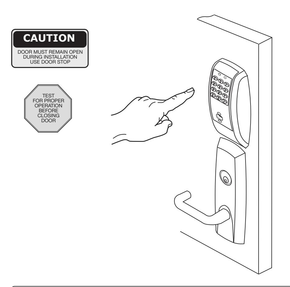
- 5. Enter 1234 to unlock outside lever and retract latch.
- 6. If lock is prox only (M802) or RF Technology with prox (M805) refer to keypad programming instructions (FM226) to program lock with a PDA use Accessware™ with Access HH application software.
225 Episcopal Road Corbin Russwin, Inc.
www.corbinrusswin.comcopyright 2007
Corbin Russwin, Inc. Technical Product Support: Berlin, CT 06037-4004 Phone 800-810-WIRE (9473)
Canada: Assa Abloy DSS Canada 160 Four Valley Drive Vaughun, ONT L4K 4TG www.yalecorbin.on.ca

Hardwiring options include one or a combination of the following: M861 Forced Door Propped Door Option, M35 Power/Remote Unlocking Harness
10.1 Important
- 1. Caution: disconnect all input power before beginning installation to prevent electrical shock and equipment damage.
- 2. Installer must be a trained, experienced service person.
- 3. All wiring must comply with applicable local electrical codes, ordinances and regulations.
10.2 Installation Notes
- 1. With new applications, an ElectroLynx™ door harness with 8 and 4 pin connectors will be pre-installed inside door by ASSA ABLOY door manufacturer when specified during ordering process.
- 2. Wiring to pigtail harness is per facility wiring requirement. ElectroLynx™ connector terminations and wire colors all match.
- 3. If door does not have an ElectroLynx™ type door harness, cut connectors off product and hard wire, or consult factory for appropriate mating harness.
10.3 ElectroLynx™ Connector System Notes:
The system is designed to be installation friendly with pluggable connectors from the electric hinge through the door to the rail. The only wiring required is to the loose wires on the pigtail harness assembly on the frame side of the electric hinge.
IMPORTANT
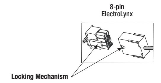
The plug and receptacle connectors are designed to mate and lock together as shown in the figure. Plug the connectors into each other with the locking mechanism aligned as indicated.
Do NOT Force connectors on any other way.


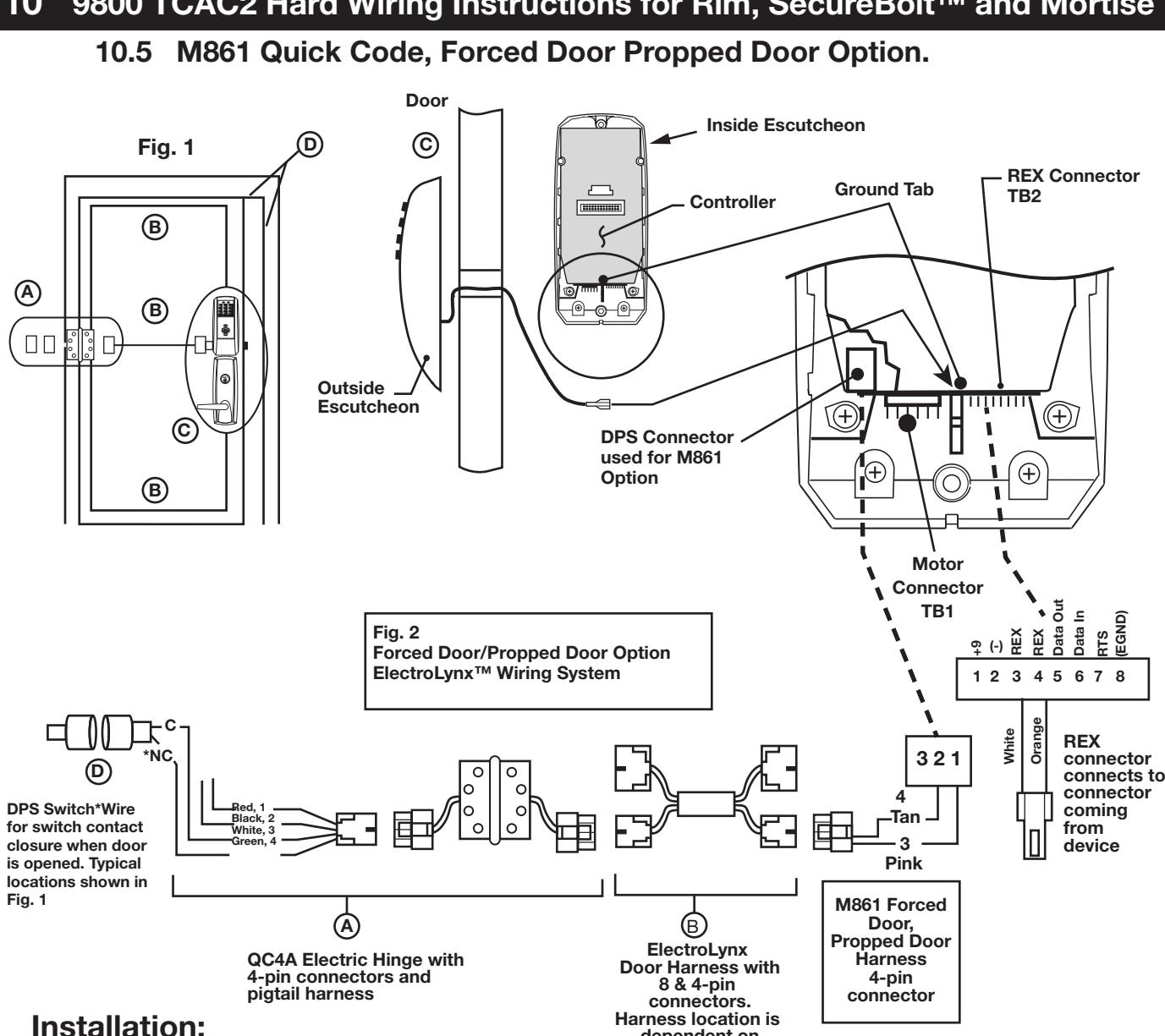
-
1. ElectroLynx<sup>™</sup> System Wiring Instructions (refer to Fig. 1 and Fig. 2)
- a. Look for the mating part on ASSA ABLOY doors and frames. Then plug in all connectors as shown in Fig. 2 during product installation.
dependent on door type.
- b. Hard-wire DPS switch as shown.
-
2. Non-ElectroLynx™ System Wiring Instructions (refer to Fig. 1 and Fig. 2)
- a. Cut the 4-pin connector off the Forced Door Propped Door harness and hard wire to ElectroLynx™ two conductor door harness.
- b. Hard wire door harness to power transfer device.
- c. Hard wire DPS switch to power transfer device.
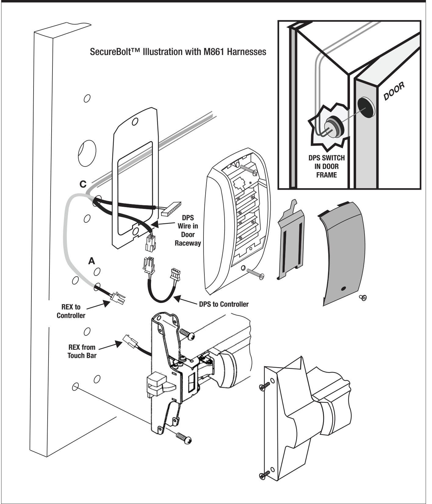
For M861 Option refer to page 19 for illustrations:
Install the REX harness by feeding the 2 pin REX connector down thru hole "C" and into the trim assembly cavity. Then take 2 pin REX connector and feed it thru the hole below hole marked "A" and connect it to the 2 pin REX connector coming from the device. This connection will be contained under the device cover. Page 19 illustrates the connection required for the M861 Door Position Switch (DPS). Connect the 3 pin M861 DPS connector to the controller and connect the 4 pin DPS connector to the 4 pin DPS connector coming out of the door.

10.6 M35 Power/Remote Unlocking Harness Door 6 AA batteries MUST be removed from controller if 784 Power supply is used. Remote Power and REX Escutcheen Ground Tab Connector TB2 Outside Escutcheon 784 9VDC ±9 VDC Power Supply EGND - 120 VAC L/N/G -Motor Conector Normally Open Fig. 3 momentary switch ă Power/Remote Unlocking (Remote unlock- ElectroLynx Wiring System REX option) 3 4 5 6 7 M35 Power/Remote Orange White Brown Yellow Unlocking Blue Red 2 Green, 4 QC8 Electric Hinge with ElectroLynx Door Harness 8-pin connectors, with 8 & 4-pin connectors. 8 wires and pigtail harness Harness location is RFX Input Connect dependent on door type. to Device. Installation: Only used in combination with 1. ElectroLynx™ System Wiring Instructions (refer to Fig. 1 and Fig. 3) the M861 Option. a. Look for the mating part on ASSA ABLOY doors and frames. Then plug in all It may be left
- connectors as shown in Fig. 3 during product installation.
- b. Hard wire 784 power supply as shown.
- 2. Non-ElectroLynx<sup>™</sup> System Wiring Instructions (refer to Fig. 1 and Fig. 3)
-
a. Cut the 8-pin connector off the Power/Remote Unlocking harness and hard wire to non-ElectroLynx™ door harness. Remote power requires three conductors and
- remote unlock requires two conductors.
- b. Hard wire door harness to power transfer device.
- c. Hard wire 784 power supply as shown.
unconnected.

ASSA ABLOY
10 9800 TCAC2 Hard Wiring Instructions for Rim, SecureBolt™ and Mortise
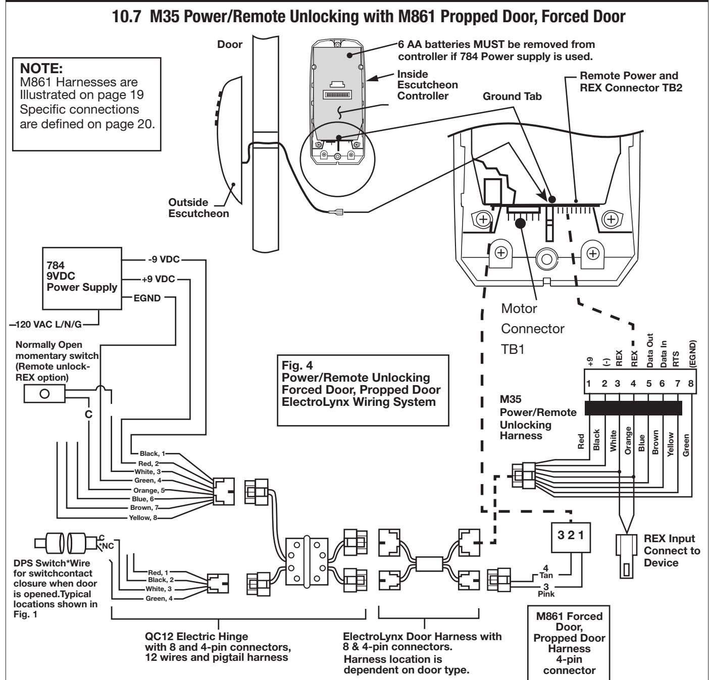
Installation:
- 1. ElectroLynx™ System Wiring Instructions (refer to Fig. 1 and Fig. 4)
- a. Look for the mating part on ASSA ABLOY doors and frames, then plug in all connectors as shown in Fig. 4 during product installation.
- b. Hard wire forced/propped, hard power and/or remote unlock (REX) as shown.
- 2. Non-ElectroLynx™ System Wiring Instructions (refer to Fig. 1 and Fig. 4)
- a. Cut the 8-pin connector off the Power/Remote Unlock harness and hard wire to non-ElectroLynx<sup>™</sup> door harness. Remote power requires three conductors and remote unlock requires two conductors.
- b. Hard wire door harness to power transfer device.
- c. Hard wire forced/propped, hard power and/or remote unlock (REX), as shown.

Corbin Russwin 225 Episcopal Road Berlin, CT 06037 Phone: 800-543-3658 Fax: 800-447-6714 corbinrusswin.com
ASSA ABLOY is the global leader in door opening solutions, dedicated to satisfying end-user needs for security, safety and convenience