Corbin Russwin Access 600 RNE1 iCLASS SE Reader Option Multi-Point Lock Install Instructions_FM453
Open the original PDF document
View PDFInstallation Instructions

Access 600®
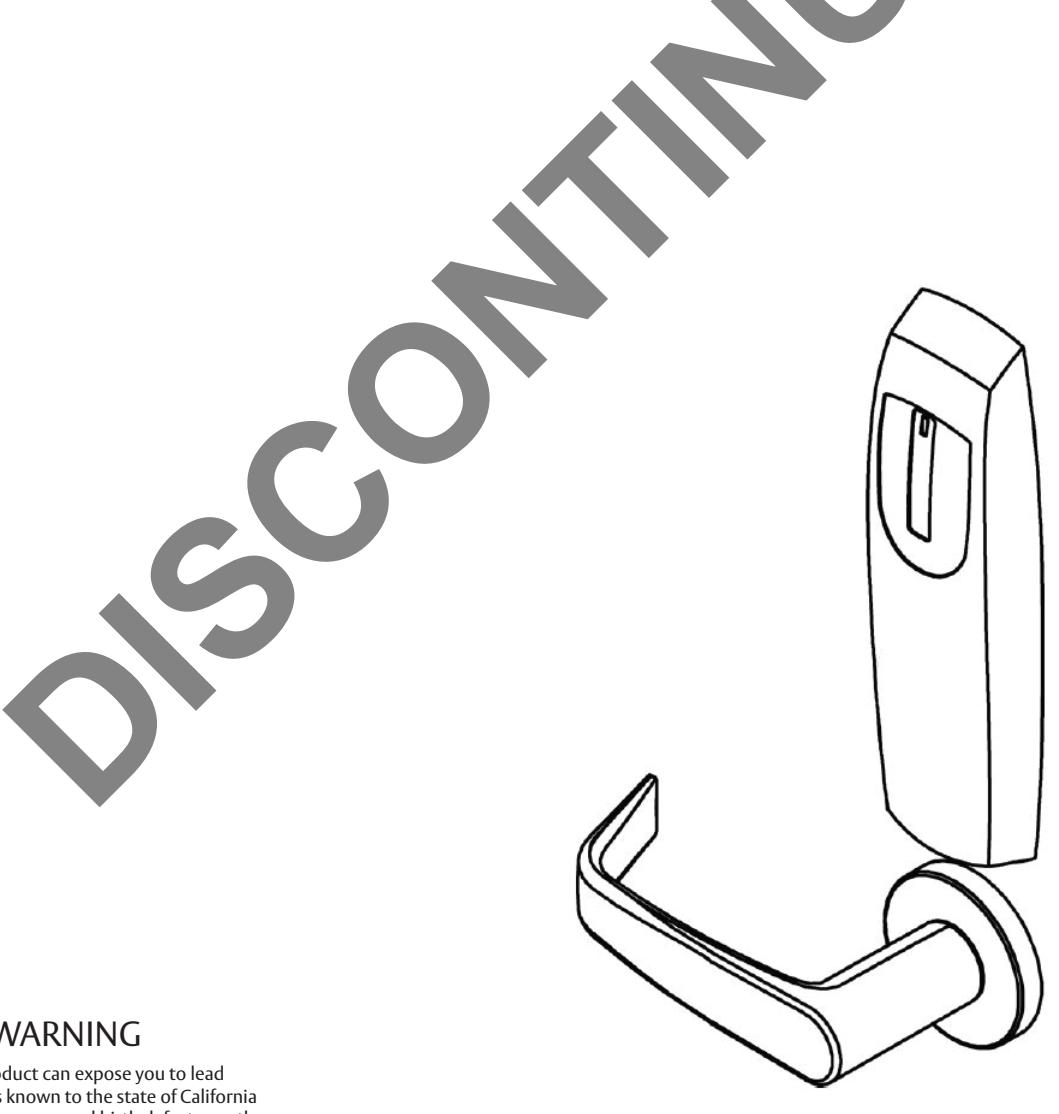
FE6600/BL6600/MP6600 Series Multi-Point Lock TCRNE1 Series with iClass SE® Reader Option

This product can expose you to lead which is known to the state of California to cause cancer and birth defects or other reproductive harm. For more information go to www.P65warnings.ca.gov.
FE6600/BL6600/MP6600 Series Multi-point Lock
Installation Instructions

| TOC | Table of Contents | |
|---|---|---|
| 1 | Warning3 | |
| 2 | General Description4 | |
| 3 | Features4 | |
| 4 | Regulatory Specifi cations5 | |
| 5 |
Wiring Diagrams
5 |
|
| 6 | Product Illustrations8 | |
| 7 |
Installation Instructions
10 |
|
| a | Verify Hand and Bevel of Door 10 | |
| b | Door Preparation 10 | |
| c | Prepare Lock Body (if necessary) 11 | |
| d | Confi gure the DIP Switch Settings 12 | |
| e | Install Lock Body 12 | |
| f | Outside Escutcheon and Mounting Plate Installation 13 | |
| g | Install Inside Gasket (if necessary) 14 | |
| h | Outside Lever and Inside Adapter Plate Assembly Installation 15 | |
| i |
Installing Controller
16 |
|
| j |
Install Inside Escutcheon Assembly
18 |
|
| k | Install Inside Rose and Inside Lever Assembly 18 |
or in part without the express written permission of ASSA ABLOY Access and Egress Hardware Group, Inc. is prohibited.
FE6600/BL6600/MP6600 Series Multi-point Lock
Installation Instructions

| TOC | Table of Contents, continued |
|---|---|
| 1 | Attaching Front Plate |
| 8 | Operational Check |
| 9 | Wiegand Test Unit |
1 Warning
Warning: Changes or modifications to this unit not expressly approved by the party responsible for compliance could void the user's authority to operate the equipment.
This device complies with Part 15 of the FCC Rules. Operation is subject to the following two conditions: (1) this device may not cause harmful interference, and (2) this device must accept any interference received, including interference that may cause undesired operation.
Note: This equipment has been tested and found to comply with the limits for a Class B digital device, pursuant to Part 15 of the FCC Rules. These limits are designed to provide reasonable protection against harmful interference in a residential installation.
This equipment generates, uses and can radiate radio frequency energy and if not installed and used in accordance with the instructions, may cause harmful interference to radio communications. However, there is no guarantee that the interference will not occur in a particular installation. If this equipment does cause harmful interference to radio or television reception, which can be determined by turning the equipment off and on, the user is encouraged to try to correct the interference by one or more of the following measures:
- Reorient or relocate the receiving antenna.
- Increase the separation between the equipment and receiver.
- Connect the equipment into an outlet on a circuit different from that to which the receiver is connected.
- Consult the dealer or an experienced technician for help.
Contains FCC ID: U4A-SCSEHF
Contains IC: 6982A-SCSEHF
The term "IC:" before the radio certification number only signifies that Industry Canada technical specifications were met. This Class B digital apparatus meets all requirements of the Canadian Interference Causing Equipment Regulations. Operation is subject to the following two conditions: (1) this device may not cause harmful interference, and (2) this device must accept any interference received, including interference that may cause undesired operation.
Cet appareillage numérique de la classe B répond à toutes les exigences de l'interférence canadienne causant des règlements d'équipement. L'opération est sujette aux deux conditions suivantes: (1) ce dispositif peut ne pas causer l'interférence nocive, et (2) ce dispositif doit accepter n'importe quelle interférence reçue, y compris l'interférence qui peut causer l'opération peu désirée.
To comply with "Fire Listed" doors, the batteries must be replaced with alkaline batteries only.

To avoid possible damage from electostatic discharge (ESD), some basic precautions should be used when handling electronic components:
and more open world
Installation Instructions

1 Warning, continued
- Minimize build-up of static by touching and/or maintaining contact with unpainted metal surfaces such as door hinges, latches, and mounting plates especially when mounting electronic components such as readers and controllers onto the door.
- Leave components (reader and controller) protected in their respective anti-static bags until ready for installation.
- Do not touch pins, leads or solder connections on the circuit boards.
*Any retrofit or other field modification to a fire rated opening can potentially impact the fire rating of the opening, and Corbin Russwin, Inc. makes no representations or warranties concerning what such impact may be in any specific situation. When retrofitting any portion of an existing fire rated opening, or specifying and installing a new fire-rated opening, please consult with a code specialist or local code official (Authority Having Jurisdiction) to ensure compliance with all applicable codes and ratings.
2 General Description
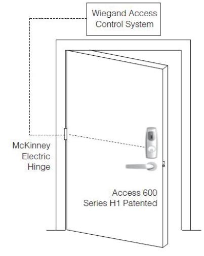
The Corbin Russwin Access 600® TCRNE1 Series multi-point lock is designed to interface with existing Wiegand Electronic Access Control (EAC) panels. The reader requires 12 or 24VDC for power and iscompatible with HID® iCLASS SE® 13.56 technology. The Access 600 technology is designed around Corbin Russwin's Grade 1 hardware.
The multi-point lock comes with complete door monitoring which is all integrated inside the lockbody and is available in 12VDC or 24VDC.
Weather seal gaskets are also included for outdoor applications. The Access 600 reader provides visual (LED) and audible indication of lock state (locked/unlocked).
3 Features
- Latch: Stainless steel, 3⁄4" projection, one-piece
- Deadbolt: One-piece hardened stainless steel
- Guardbolt: Stainless steel, non-handed
- Handed: Easily field reversible without opening case
- Case: 12 gauge heavy duty wrought steel
- Outside lever controlled by 13.56MHz HID iCLASS SE credential
- Field-selectable to Fail Safe or Fail Secure
- Door position switch within lock body
- Inside lever provides RX signal and retracts latch and deadbolt
- Lock to be configured* as Fail Safe or Fail Secure per AHJ compliance as part of initial lock configuration
- Locks furnished for 1-3/4" doors. Other door thicknesses require confirmation with factory.
-
Supported credentials:
- iCLASS®
- CLASS SE® (SIO-enabled)
- iCLASS® Seos®
- HID SIO on MIFARE® Classic
- HID SIO on MIFARE DESFire® EV1
- NFC-enabled mobile phones
FM453 07/20
Installation Instructions

4 Regulatory Specifi cations
12/24VDC System
- Reader Draw = 150mA @12VDC/24VDC
- Actuator Draw = 400mA inrush/15mA continuous @12VDC/24VDC
- Solenoid Draw = 500 mA @12VDC 250 mA @24VDC
- Total System Draw = 550mA @12VDC / 24VDC
- UL and CUL listed for use on Fire Doors
Wiring methods shall be in accordance with the National Electrical Code (ANSI/NFPA70), CSA 22.1, Canadian Electrical Code (CEC), Part I, Safety Standard for Electrical Installations, local codes, and the authorities having jurisdiction.
5 Wiring Diagrams
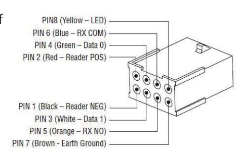
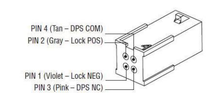
| Product | 8 PIN CONNECTOR | 4 PIN CONNECTOR | ||||||||||
|---|---|---|---|---|---|---|---|---|---|---|---|---|
|
1
Black |
2
Red |
3
White |
4
Green |
5
Orange |
6
Blue |
7
Brown |
8
Yellow |
1
Violet |
2
Gray |
3
Pink |
4
Tan |
|
| ACCESS CONTROL DEVICES: Access 600 FE6600/BL6600/MP6600 Multi-point, ElectroLynx wire Color / Function assignments | ||||||||||||
|
Corbin
Russwin |
12/24VDC
(Reader) |
WIE
GAND |
WIE
GAND |
RX | RX | EGND | LED |
12/24 VDC
(LOCK RELAY) |
DPS
(NC) |
DPS
(COM) |
||
|
FE 6600
BL6600 MP6600 Multi-point |
NEG | POS | DATA_1 | DATA_0 | NO/NC | COM |
REF.
*DIA GRAMS |
REF.
*DIA GRAMS |
NEG | POS | DPS | DPS |
|
Cylindrical/
Exits |
NEG | POS | DATA_1 | DATA_0 | NO | COM | NEG | POS | - | - | ||
See page 7 for diagram.
If your lock is confi gured with End of Line Resistors, reference instruction sheet FM406 for the wiring of RX & DPS outputs.
Reader LED Confi guration
The Access 600 series reader can be configured for (3) modes of LED operation.
Call 1-800-810-WIRE for details.
Mode 1:
- Red LED 'ON' when powered.
- Presenting a valid credential will cause LED to 'FLICKER' green and return to red state.
Mode 2:
- Green LED "ON" when powered.
- (No Flicker) after presenting valid credential.
NOTE: LED wire must be connected to circuit GROUND of the system's power supply.
Mode 3:
• EAC Panel controls LED operation.
FE6600/BL6600/MP6600 Series Multi-point Lock
Installation Instructions

5 Wiring Diagrams, continued
NOTE: Control of LED is a function of the EAC panel equipment (i.e. relay) to toggle between green and red. NOTE: When LED wire is tied directly into EAC panel relay, no AC signals should be applied on wire - door reader performance will be impacted.
Wire from EAC panel to door must be shielded with drain terminated at EAC panel controller.
Wire Gauge Charts
|
Total
One-Way |
Load Current @ 12VDC | |||||||
|---|---|---|---|---|---|---|---|---|
|
Length of
Wire Run (ft) |
1/4A | 1/2A | 3/4A | 1A | 1-1/4A | 1-1/2A | 2A | 3A |
| 100 | 20 | 18 | 16 | 14 | 14 | 12 | 12 | 10 |
| 150 | 18 | 16 | 14 | 12 | 12 | 12 | 10 | — |
| 200 | 16 | 14 | 12 | 12 | 10 | 10 | — | — |
| 250 | 16 | 14 | 12 | 10 | 10 | 10 | — | — |
| 300 | 16 | 12 | 12 | 10 | 10 | — | — | — |
| 400 | 14 | 12 | 10 | — | — | — | — | — |
| 500 | 14 | 10 | 10 | — | — | — | — | — |
| 750 | 12 | 10 | — | — | — | — | — | — |
| 1,000 | 10 | — | — | — | — | — | — | — |
| 1,500 | 10 | — | — | — | — | — | — | — |
|
Total
One-Way |
Load Current @ 24VDC | ||||||||
|---|---|---|---|---|---|---|---|---|---|
|
Length of
Wire Run (ft) |
1/4A | 1/2A | 3/4A | 1A | 1-1/4A | 1-1/2A | 2A | 3A | |
| 100 | 24 | 20 | 18 | 18 | 16 | 16 | 14 | 12 | |
| 150 | 22 | 18 | 16 | 16 | 14 | 14 | 12 | 10 | |
| 200 | 20 | 18 | 16 | 14 | 14 | 12 | 12 | 10 | |
| 250 | 18 | 16 | 14 | 14 | 12 | 12 | 12 | 10 | |
| 300 | 18 | 16 | 14 | 12 | 12 | 12 | 10 | — | |
| 400 | 18 | 14 | 12 | 12 | 10 | 10 | — | — | |
| 500 | 16 | 14 | 12 | 10 | 10 | — | — | — | |
| 750 | 14 | 12 | 10 | 10 | — | — | — | — | |
| 1,000 | 14 | 10 | 10 | — | — | — | — | — | |
| 1,500 | 12 | 10 | — | — | — | — | — | — | |
For installation assistance contact Corbin Russwin
or in part without the express written permission of ASSA ABLOY Access and Egress Hardware Group, Inc. is prohibited.
Installation Instructions

5
Wiring Diagrams, continued
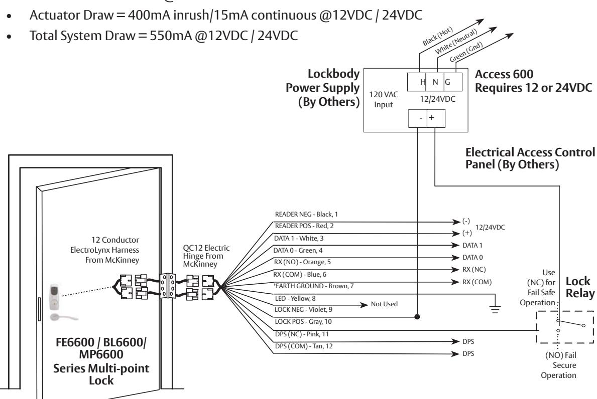
Typical FE6600/BL6600/MP6600 x M812 Series Multi-point Lock Application Diagram (12/24VDC Lock)
Standard Application Shown.
For Alternative Applications Contact 1-800-810-WIRE (9473).
Reader Electronics Require 12 or 24VDC Power Supply
12/24VDC System
Reader Draw = 150mA @12 or 24VDC

*IMPORTANT:
Pin 7 must be tied to ground in the access control panel.
Failure to follow proper ESD safe grounding procedures could lead to equipment failure.
NOTE:
If your lock is configured with End of Line Resistors, reference instruction sheet FM406 for the wiring of RX & DPS outputs.
Installation Instructions

6 Product Illustrations
FE6600/BL6600/MP6600 Series Multi-point Lock
Installation Instructions

6 Product Illustrations, continued
Lever Hand Reverse Door, continued
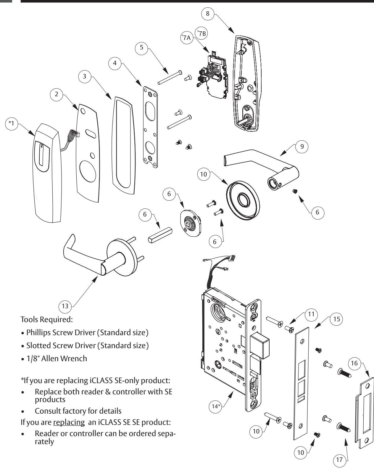
| Item | Description | |||||
|---|---|---|---|---|---|---|
| *1 | Outside Access 600 Escutcheon/Reader | |||||
| 2 | Outside Weather Gasket | 1 | ||||
| 3 | Inside Weather Gasket | 1 | ||||
| 4 | Inside Mounting Plate | 1 | ||||
| 5 | Screw Pack (5A; 5B; 5C; 5D) | 1 | ||||
| 6 | Trim Pack - Standard levers | 1 | ||||
| Trim Pack - Muséo levers | ||||||
| *7A | Standard controller | 1 | ||||
| *7B | GE IA-02 Controller Assembly - iCLASS SE only | |||||
| 8 | Inside Escutcheon w/ Turn Assembly | |||||
| 9 | Reference Access 600 Series Catalog For Available Lever Styles | |||||
| 10 | Reference Access 600 Series Catalog For Available Rose Styles | |||||
| 11 |
Mortise screw pack - specify finish
(includes: wood & metal lock body screws, faceplate screws & strike screws) |
|||||
| 12 | Reference Access 600 Series Catalog For Available Lever Styles | |||||
| *14 | w/ Deadbolt, Fail Safe | 1 | ||||
| w/ Deadbolt, Fail Secure | ||||||
| w/ Deadbolt, Fail Safe | ||||||
| w/ Deadbolt, Fail Secure | ||||||
| 15 | Electrical Outside Faceplate | |||||
| 16 | Strike Plate | |||||
| 17 | #12 X 1 1/4" Phillips Flat Head Wood Screw | |||||
Patent pending and/or patent - www.assaabloydss.com/patents.
Installation Instructions

7
Installation Instructions
а
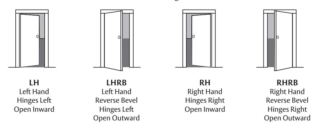
Verify Hand and Bevel of Door
Stand on outside of locked door when determining door hand.
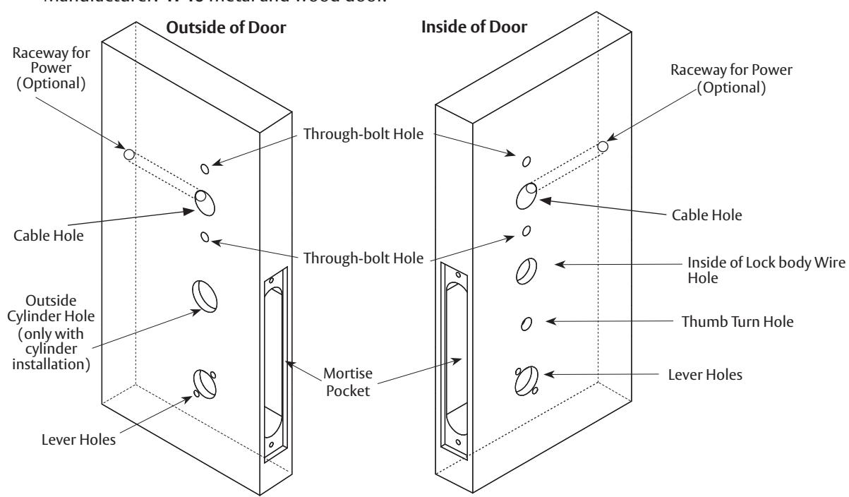
b Door Preparation
Prepare door according to appropriate template. If necessary, refer to website: www.intelligentopenings.com
- Prior to installation, make sure all holes are free of burrs, debris and sharp edges.
- If doors are not properly reinforced per ANSI 115.2, commercially available reinforcements should be installed.
Templates:
- Field: FM442 template ships with product.
- Manufacturer: 4740 metal and wood door.
FM453 07/20
10
Installation Instructions

7 Installation Instructions, continued
c Prepare Lock Body (if necessary)
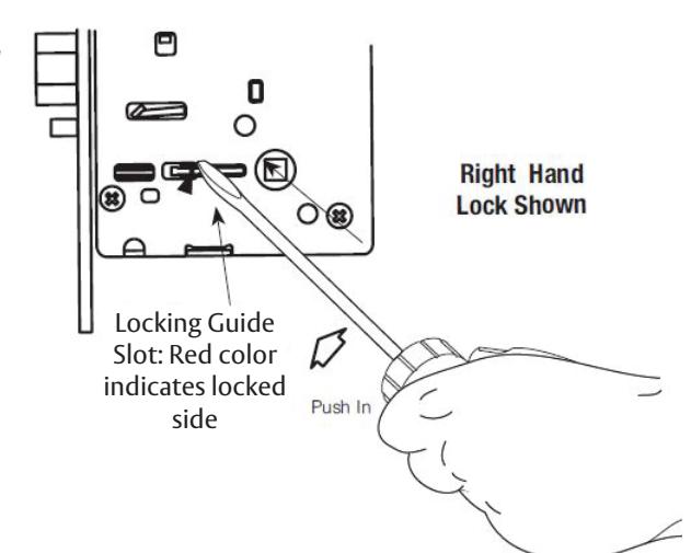
Reverse Lock Hand
Red surface of locking piece must face the outside/ locked side of door.
- 1. To rotate locking piece, position lock body with red surface of locking piece visible. See figure to the right.
- 2. Insert blade type screwdriver into locking piece slot to rotate locking piece toward back of lock body.
- 3. Rotate the locking piece 180° until RED surface is on opposite side.
NOTE: Red indicates locked side (outside).
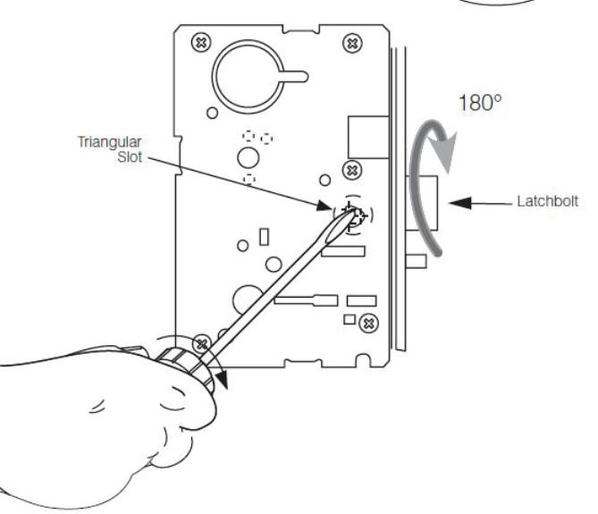
The beveled surface of the latch must face the strike. See image to the right. The dead latch is self adjusting.
To change hand of the latchbolt:
- 1. Insert screwdriver into the spade shaped slot.
- 2. Rotate the screwdriver 90º to push the latch out until the back of the latch clears the lock front.
- 3. Rotate the latch 180º . The latch will then re-enter the lock body.
NOTE: The latch cannot be unscrewed.
FM453 07/20
Installation Instructions

7 Installation Instructions, continued
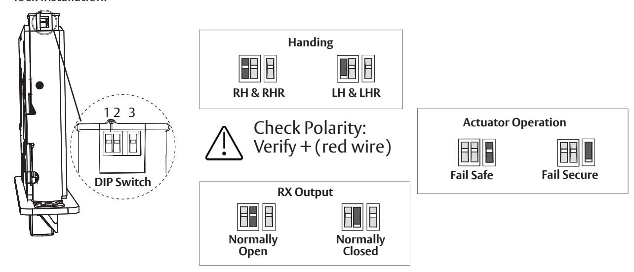
d Confi gure the DIP Switch Settings
IMPORTANT: This product is built and factory tested to the configuration specified. Any change to the 3-position DIP-switch settings located at the bottom of the mortise lock body must be made prior to lock installation.
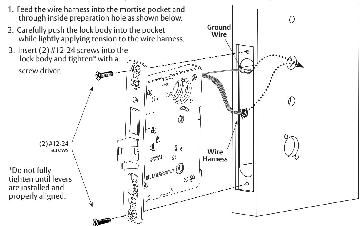
e Install Lock Body
NOTE: Do not pull the lock into the pocket using the harness alone.
Ensure that the wire harness is not pinched between the lock and the mortise pocket.
FM453 07/20
Installation Instructions

7 Installation Instructions, continued
f Outside Escutcheon and Mounting Plate Installation
NOTE: Feed mortise connectors through the corresponding hole on the mounting plate.
- 1. Attach the mounting plate using (2) #8-32 x 3/8" Phillips flat head undercut combo screws in the upper left and middle right positions of the mounting plate and (2) #8-32 x 3/8" Phillips flat head screws in the bottom positions.
- 2. Feed the reader cable located on the back of the outside escutcheon through the door prep. Remember, the outside gasket must be used when installing in an outdoor application (Figure 1).
- 3. Secure the mounting plate to the outside escutcheon with (2) #8-32 x 2" flat head machine screws (Figure 2).
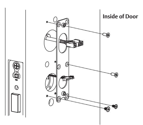

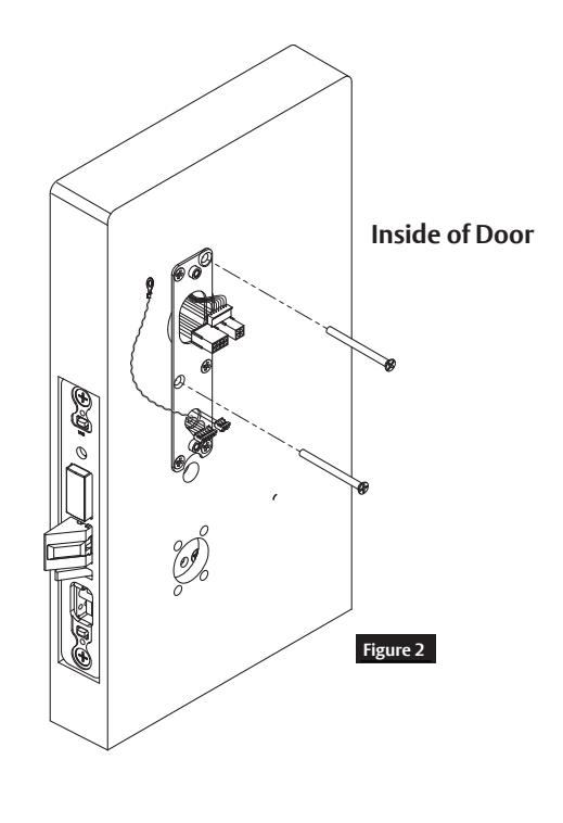
Figure 1
FE6600/BL6600/MP6600 Series Multi-point Lock
Installation Instructions

7 Installation Instructions, continued
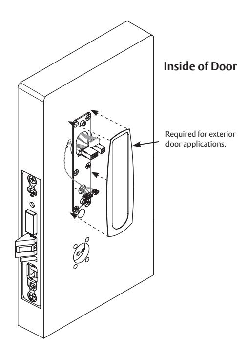
g Install Inside Gasket (if necessary)
Remember to install inside gasket when lock is being used in an outdoor application
- a. Gasket fits snug around plate at top and sides, leaving room for the hole at the bottom.
- b. Remove (peel) backing and place gasket on door.
FE6600/BL6600/MP6600 Series Multi-point Lock
Installation Instructions

7
Installation Instructions, continued
h
Outside Lever and Inside Adapter Plate Assembly Installation
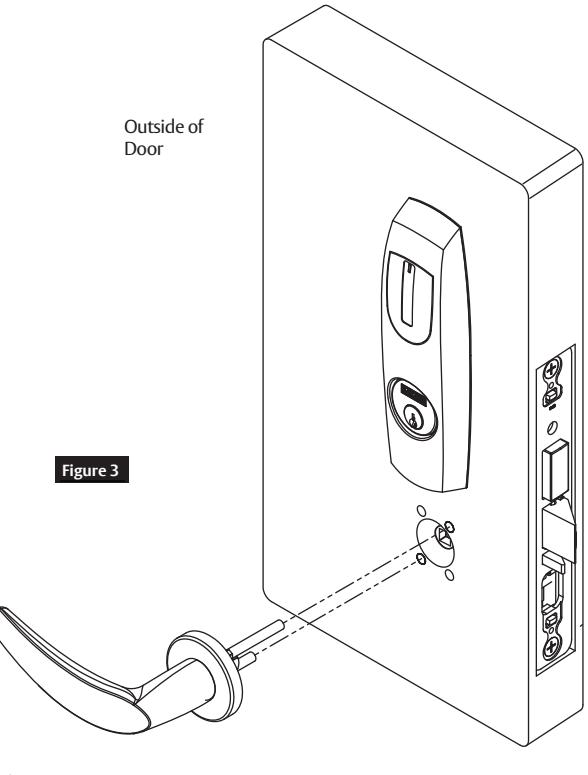
- 1. With outside lever horizontal, insert the mounting post through outside of door and lock body.
- 2. Confirm the lever spindle is properly engaged inside the lock body (Figure 3).
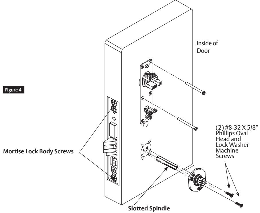
- 3. On the inside of the door, insert slotted spindle into square hole of mortise lock (Figure 4), with spindle slot directed away from the lock body, and aligned with the set screw hole in the inside adapter.
- 4. Slide inside adapter and plate assembly over spindle and loosely secure with (2) #8-32 X 5/8" Phillips oval head and lock washer machine screws.
NOTE: Ensure that position of set screw hole and spindle slot are oriented to match location of hole in the inside lever handle.
5. Securely tighten the lock body screws.
Installation Instructions

7
Installation Instructions, continued
ı
Installing Controller
Feed controller harness earth ground into and around behind rim of large upper hole of the mounting plate (See Figures 5 and 6).
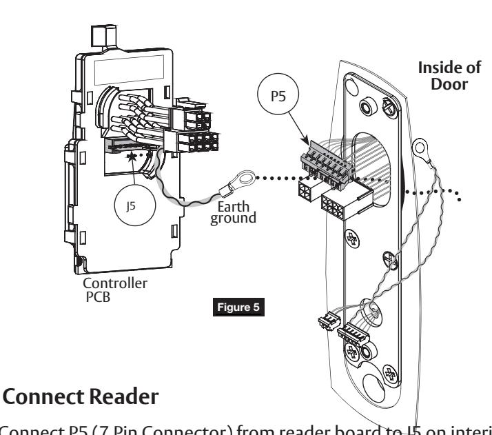


Connect ElectroLynx harness (4 and 8-pin) from door harness to ElectroLynx harness on interior PCB assembly (Figures 5 and 8).
NOTES:
- Neatly fold the wires into the remaining space to prevent pinching wires when mounting escutcheon.
- Do not tuck extra mortise lock body wires back inside the lock body cylinder hole.
- Connectors go on only one way.
Copyright © 2017, 2020 ASSA ABLOY Access and Egress Hardware Group, Inc. All rights reserved. Reproduction in whole
or in part without the express written permission of ASSA ABLOY Access and Egress Hardware Group, Inc. is prohibited.
• Do not offset connector and be sure they are completely seated.
Figure 8
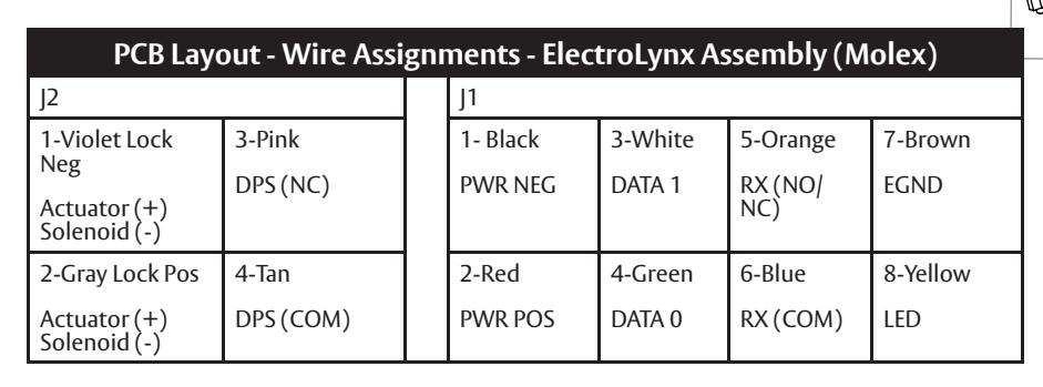
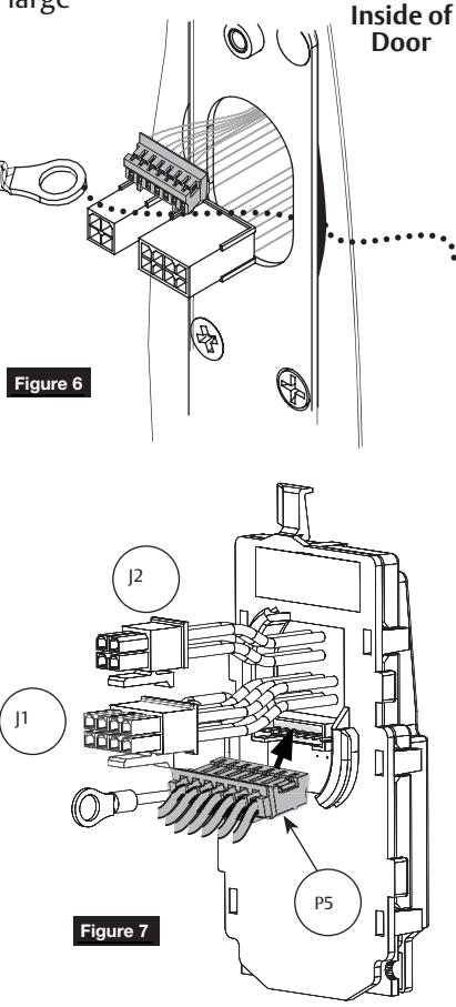
4-pin ElectroLynx
8-pin
ElectroLynx
Installation Instructions

7 Installation Instructions, continued
i Installing Controller, continued
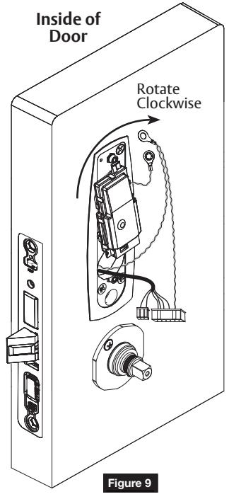
Follow these steps prior to installing inside escutcheon to prevent any damage caused by pinching wires:
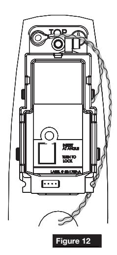
- 1. Once wires are arranged, position controller at a rotated angle against the door, under the earth ground wire.
- 2. Press piece against door while turning clockwise (Figure 9).
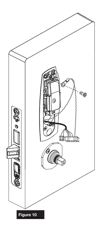
- 3. Twist into place, perpendicular with door (Figure 10).
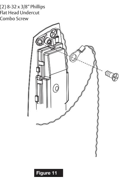
- 4. Position green/yellow ground wire ring terminal (from lock body) over hole for top left screw (Figures 10 and 11).
- 5. Position green/yellow reader harness earth ground on top of ground ring and thread both with (1) #8-32 x 3/8" Phillips flat head undercut combo screw (Figures 10 and 11).
IMPORTANT: Note orientation of ground ring terminals in the figures below.
6. Tighten securely.
Installation Instructions

7
Installation Instructions, continued
j
Install Inside Escutcheon Assembly
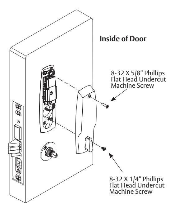
Tighten the inside escutcheon securely to the mounting plate with the Phillips flat head machine screws provided. Use the #8-32 x 5/8" for the top of the escutcheon, and the #8-32 x 1/4" screws for the bottom of the escutcheon located under the turn lever.
NOTE: The inside gasket must be used when installing in an outdoor application.
2. Check that the turn assembly is functional, and the deadbolt functions properly.
k Install Inside Rose and Inside Lever Assembly
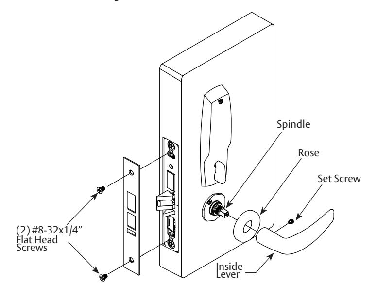
- Rotate the inside rose counterclockwise to seat the threads, then rotate clockwise to securely tighten.
- 2. Slide lever handle onto spindle until fully seated. The handle must be horizontal and facing the hinge side of the door.
- 3. Push lever onto spindle so minimum gap is visible.
- 4. Tighten the set screw securely with a 1/8" hex wrench.
- 5. Before closing the door, test that the lever is functional and that both the latchbolt and the deadbolt move without restriction.
Attaching Front Plate
Attach front plate with (2) #8-32x1/4" flat head screws and tighten securely.
FE6600/BL6600/MP6600 Series Multi-point Lock
Installation Instructions

8 Operational Check
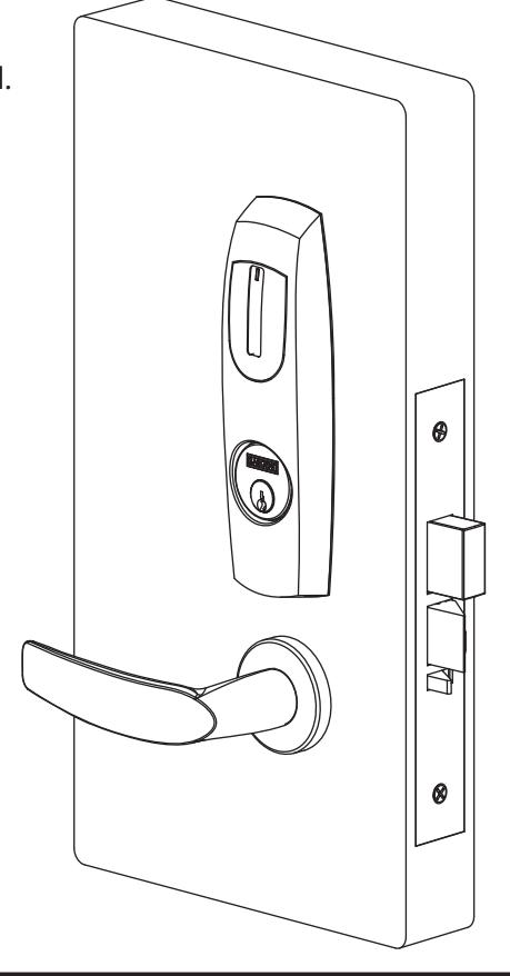
- 1. Close door.
- 2. Ensure latch and deadbolt fully extend and do not bind.
NOTE: Once electrical wiring has been successfully completed according to proper application, follow the following steps:
- 3. Turn power ON.
- 4. Verify LED located on reader is ON (Red or Green depending on reader configuration (See reader LED Configuration).
- 5. Present proximity credential and verify LED and sounder activity.
- 6. Verify valid card read at EAC panel.
- 7. Verify system operation functions; i.e. , present Prox credential to reader and unlock door.
9 Wiegand Test Unit
The ASSA ABLOY Wiegand Test Unit verifies your installation in the field. The test unit checks for proper wiring, card reader data integrity, lock functionality including lock/unlock, door position status, and request-to-exit (REX) status.
In addition, this tool provides product demonstration abilities to highlight the product's features and capabilities.
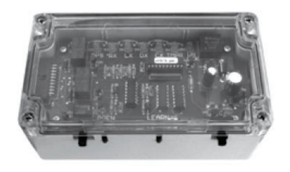
| Feature | WT1 | WT2 |
|
12 or 24VDC solenoid
lock voltage adjustable |
X | X |
|
Operates as Fail Safe or
Fail Secure |
X | X |
|
"Learn" mode allows
testing of specific cards without programming at the panel level |
X | X |
|
Card reader data integrity
is validated at test unit |
X | X |
| Works with SE LP10 | X | X |
|
Displays detailed
Wiegand data, including hexadecimal string and total bits received |
X | |
|
Displays measured end
of-line resistor values (if applicable) |
X |

Corbin Russwin 225 Episcopal Road Berlin, CT 06037 Phone: 800-543-3658