Corbin Russwin Access 600 RNE1 iCLASS SE Reader Option Mortise Lock Install Instructions_FM312
Open the original PDF document
View PDF

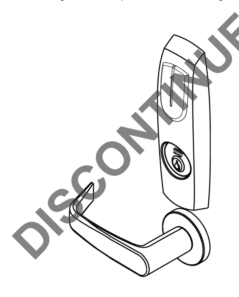
Mortise Lockset Installation Instructions ML20600 TCRNE1 Series M812 - iCLASS SE® Reader Option

FM312 10/18
Attention Installer
Please read these instructions carefully to prevent missing important steps.
Please Note: Improper installations may result in damage to the lock and void the factory warranty.
Important: The accuracy of the door preparation is critical for proper functioning and security of this lock.
Misalignment can cause premature wear and a lessening of security.
N WARNING
This product can expose you to lead which is known to the state of California to cause cancer and birth defects or other reproductive harm. For more information go to www.P65warnings.ca.gov.
08/2018
For Technical Assistance call Corbin Russwin at 1-800-810-WIRE (9473)

Table of Contents
| 1) Warning | 3 |
|---|---|
| 2) General Description | 4 |
| 3) Features | 4 |
| 4) Regulatory Specifications | 4 |
| 5) Product Illustrations | 5 |
| 6) Wiring Diagrams | 6 |
| 7) Installation Instructions | 8 |
| 8) Operational Check | 19 |
1) Warning
Warning: Changes or modifications to this unit not expressly approved by the party responsible for compliance could void the user's authority to operate the equipment.
This device complies with Part 15 of the FCC Rules. Operation is subject to the following two conditions: (1) this device may not cause harmful interference, and (2) this device must accept any interference received, including interference that may cause undesired operation.
Note: This equipment has been tested and found to comply with the limits for a Class B digital device, pursuant to Part 15 of the FCC Rules. These limits are designed to provide reasonable protection against harmful interference in a residential installation.
This equipment generates, uses and can radiate radio frequency energy and if not installed and used in accordance with the instructions, may cause harmful interference to radio communications. However, there is no guarantee that the interference will not occur in a particular installation. If this equipment does cause harmful interference to radio or television reception, which can be determined by turning the equipment off and on, the user is encouraged to try to correct the interference by one or more of the following measures:
- Reorient or relocate the receiving antenna
- Increase the separation between the equipment and receiver
- Connect the equipment into an outlet on a circuit different from that to which the receiver is connected
- Consult the dealer or an experienced technician for help
Contains FCC ID: U4A-SCSEHF Contains IC: 6982A-SCSEHF
The term "IC:" before the radio certification number only signifies that Industry Canada technical specifications were met. This Class B digital apparatus meets all requirements of the Canadian Interference Causing Equipment Regulations. Operation is subject to the following two conditions: (1) this device may not cause harmful interference, and (2) this device must accept any interference received, including interference that may cause undesired operation.
Cet appareillage numérique de la classe B répond à toutes les exigences de l'interférence canadienne causant des règlements d'équipement. L'opération est sujette aux deux conditions suivantes: (1) ce dispositif peut ne pas causer l'interférence nocive, et (2) ce dispositif doit accepter n'importe quelle interférence recue, y compris l'interférence qui peut causer l'opération peu désirée.
Any retrofit or other field modification to a fire rated opening can potentially impact the fire rating of the opening, and Corbin Russwin® makes no representations or warranties concerning what such impact may be in any specific situation. When retrofitting any portion of an existing fire rated opening, or specifying and installing a new fire-rated opening, please consult with a code specialist or local code official (Authority Having Jurisdiction) to ensure compliance with all applicable codes and ratings.

Observe precautions for handling electrostatic sensitive devices.
Warning: To comply with "Fire Listed" doors, only alkaline batteries must be used.

2) General Description
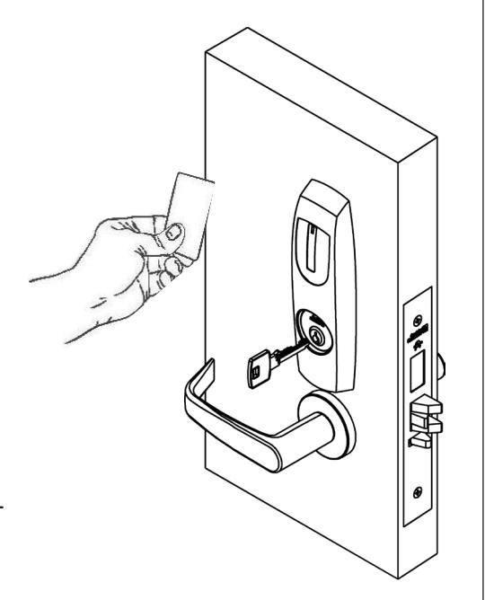
The Corbin Russwin Access 600™ TCRNE1 Series mortise lock is designed to interface with existing Wiegand Electronic Access Control (EAC) panels. The reader requires 12 or 24 VDC for power and is compatible with HID iCLASS SE® 13.56 MHz technology. The Access 600 technology is designed around Corbin Russwin's Grade 1 hardware. The mortise lock comes with complete door monitoring, which is all integrated inside the lockbody and is available in 12VDC or 24VDC. The Access 600 reader provides visual (LED) and audible indication of lock state (locked/unlocked). Weatherseal gaskets are also included for outdoor applications.
3) Features
- Latch Stainless Steel (Easily field reversible without disassembling lockbody)
- Deadbolt Stainless Steel
- Auxiliary Latch Stainless steel, non-handed
- Door Thickness 1-3/4" Standard; Can be furnished for other door thicknesses upon request. Consult factory.
- Case 12 gauge heavy duty wrought steel
- Outside lever controlled by reader or key retracts latch
- Inside lever produces REX (request to exit) signal and retracts latch and deadbolt
- Fail Safe or Fail Secure operation
- UL fire listed
- McKinney QC12 Hinge with ElectroLynx® plug and play
-
Supported credentials:
- iCLASS®
- iCLASS SE® (SIO-enabled)
- iCLASS® Seos®
- HID SIO on MIFARE® Classic
- HID SIO on MIFARE DESFire® EV1
- NFC-enabled mobile phones
4) Regulatory Specifications
12VDC System
- Reader Draw = 150mA
- Actuator Draw = 400mA inrush / 15mA continuous @12VDC / 24VDC
- Total System Draw = 550mA
- UL 294 Access Control Performance Ratings:
24VDC System
- Reader Draw = 150mA
- Actuator Draw = 400mA inrush / 15mA continuous@12VDC / 24VDC
- Total System Draw = 550mA
| Destructive Attack | Level I |
|---|---|
| Line Security | Level I |
| Endurance | Level IV |
| Standby Power | Level I |
- UL294 6th Edition (Access Control System Units)
- This product meets the requirements of CAN/ULC-S319-05 Equipment Class I
- ANSI/BHMA A156.25 Listed Grade 1 Compliant
Wiring methods shall be in accordance with the National Electrical Code (ANSI/NFPA70), CSA 22.1, Canadian Electrical Code (CEC), Part I, Safety Standard for Electrical Installations, local codes, and the authorities having jurisdiction.

5) Product Illustration
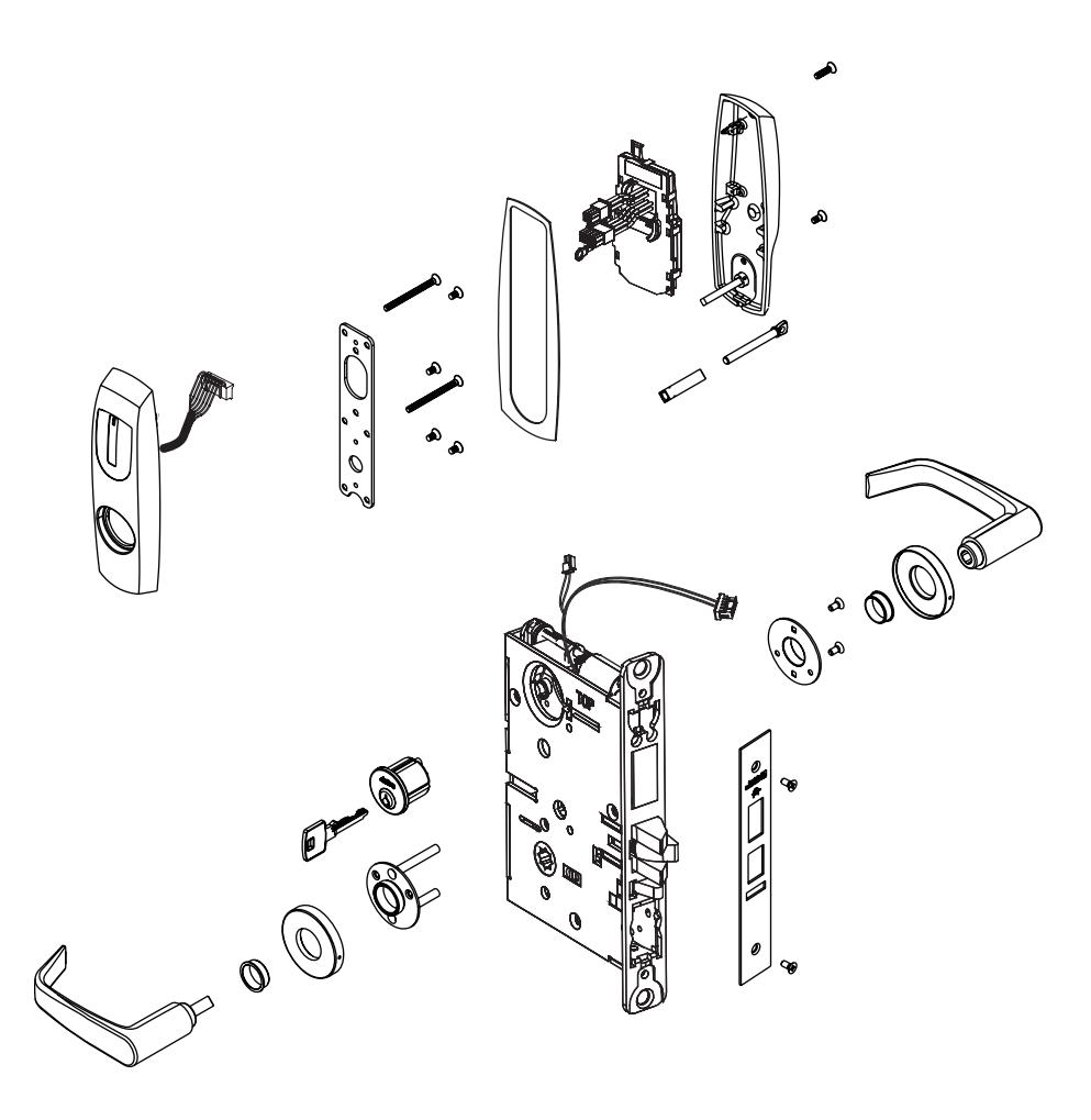
| Item | Part Number | Description | Req. |
|---|---|---|---|
| 1 | 743F312 26D | Esc SA, M812 - Mortise No Cyl/ No TP Function (ML20607) | 1 |
| 743F322 26D | Esc SA, M812 - Mortise Cyl/ No TP Function (ML20606) | ||
| 743F332 26D | Esc SA, M812 - Mortise Cyl/ with TP Function (ML20608) | ||
| 743F342 26D | Esc SA, M812 - Mortise No Cyl/ with TP Function (ML20609) | ||
| 2 | 744F859 | Controller (M812) | 1 |
| 3 | 816F008 [handing]* | ML20606/ML20607 Fail Safe (SAF) | 1 |
| 816F018 [handing]* | ML20606/ML20607 Fail Secure (SEC) | ||
| 816F028 [handing]* | ML20608/ML20609 Fail Safe (SAF | ||
| 816F038 [handing]* | ML20608/ML20609 Fail Safe (SAF) |

6) Wiring Diagrams
| Product | 8 PIN CONNECTOR | 4 PIN CONNECTOR | |||||||||||
|---|---|---|---|---|---|---|---|---|---|---|---|---|---|
| 1-Black | 2-Red | 3-White | 4-Green | 5-Orange | 6-Blue | 7-Brown | 8-Yellow | 1-Violet | 2-Gray | 3-Pink | 4-Tan | ||
| ACCESS CONTROL DEVICES: Harmony H2 Mortise, ElectroLynx wire Color / Function assignments | |||||||||||||
|
Corbin Russwin
Access 600 Mortise |
12/24VDC
(Reader) |
WIE- GAND | WIE- GAND | RX | RX | EGND | LED |
12/24 VDC
(LOCK RELAY) |
DPS
(NC) |
DPS
(COM) |
|||
| NEG | POS | DATA_1 | DATA_0 | NO | COM |
REF.
*DIA- GRAMS |
REF.
*DIA- GRAMS |
NEG | POS | DPS | DPS | ||
| Cylindrical/Exits | NEG | POS | DATA_1 | DATA_0 | NO | COM | NEG | POS | - | - | |||
* Diagram on following page
If your lock is configured with End of Line Resistors, reference instruction sheet FM406 for the wiring of RX & DPS outputs.
Reader LED Configuration
The Access 600 series reader can be configured for (3) modes of LED operation. Call 1-800-810-WIRE for details.
Mode 1:
- Red LED 'ON' when powered.
- Presenting a valid credential will cause LED to 'FLICKER' green and return to red state.
Mode 2:
- Green LED "ON" when powered.
- (No Flicker) after presenting valid credential.
Note: LED wire must be connected to circuit GROUND of the system's power supply.
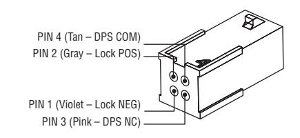
PIN8 (Yellow – LED) PIN 6 (Blue – RX COM) PIN 4 (Green – Data 0) PIN 2 (Red – Reader POS) PIN 1 (Black – Reader NEG) PIN 3 (White – Data 1) PIN 5 (Orange – RX NO) PIN 7 (Brown - Earth Ground)
Mode 3:
• EAC Panel controls LED operation.
Note: Control of LED is a function of the EAC panel equipment (i.e. relay) to toggle between green and red.
Note: When LED wire is tied directly into EAC panel relay, no AC signals should be applied on wire door reader performance will be impacted.
Wire from EAC panel to door must be shielded with drain terminated at EAC panel controller
Wire Gauge Charts
|
Total
One-Way |
Load Current @ 12VDC | ||||||||
|---|---|---|---|---|---|---|---|---|---|
|
Length of
Wire Run (ft) |
1/4A | 1/2A | 3/4A | 1A | 1-1/4A | 1-1/2A | 2A | 3A | |
| 100 | 20 | 18 | 16 | 14 | 14 | 12 | 12 | 10 | |
| 150 | 18 | 16 | 14 | 12 | 12 | 12 | 10 | — | |
| 200 | 16 | 14 | 12 | 12 | 10 | 10 | — | — | |
| 250 | 16 | 14 | 12 | 10 | 10 | 10 | — | — | |
| 300 | 16 | 12 | 12 | 10 | 10 | — | — | — | |
| 400 | 14 | 12 | 10 | — | — | — | — | — | |
| 500 | 14 | 10 | 10 | — | — | — | — | — | |
| 750 | 12 | 10 | — | — | — | — | — | — | |
| 1,000 | 10 | — | — | — | — | — | — | — | |
| 1,500 | 10 | — | — | — | — | — | — | — | |
|
Total
One-Way |
Load Current @ 24VDC | ||||||||
|---|---|---|---|---|---|---|---|---|---|
|
Length of
Wire Run (ft) |
1/4A | 1/2A | 3/4A | 1A | 1-1/4A | 1-1/2A | 2A | 3A | |
| 100 | 24 | 20 | 18 | 18 | 16 | 16 | 14 | 12 | |
| 150 | 22 | 18 | 16 | 16 | 14 | 14 | 12 | 10 | |
| 200 | 20 | 18 | 16 | 14 | 14 | 12 | 12 | 10 | |
| 250 | 18 | 16 | 14 | 14 | 12 | 12 | 12 | 10 | |
| 300 | 18 | 16 | 14 | 12 | 12 | 12 | 10 | — | |
| 400 | 18 | 14 | 12 | 12 | 10 | 10 | — | — | |
| 500 | 16 | 14 | 12 | 10 | 10 | — | — | — | |
| 750 | 14 | 12 | 10 | 10 | — | — | — | — | |
| 1,000 | 14 | 10 | 10 | — | — | — | — | — | |
| 1,500 | 12 | 10 | — | — | — | — | — | — | |

6) Wiring Diagrams (Continued)
Typical ML20600 x M812 Series Lock Application Diagram (12/24VDC Lock)
Standard Application Shown - For Alternative Applications Contact 1-800-810-WIRE (9473)
Reader Electronics Require 12 or 24VDC UL294 Listed, Power Limited Power Supply (or UL603)
12/24VDC System
- Reader Draw = 150mA @12 or 24VDC
- Actuator Draw = 15mA Continuous (400mA Inrush)
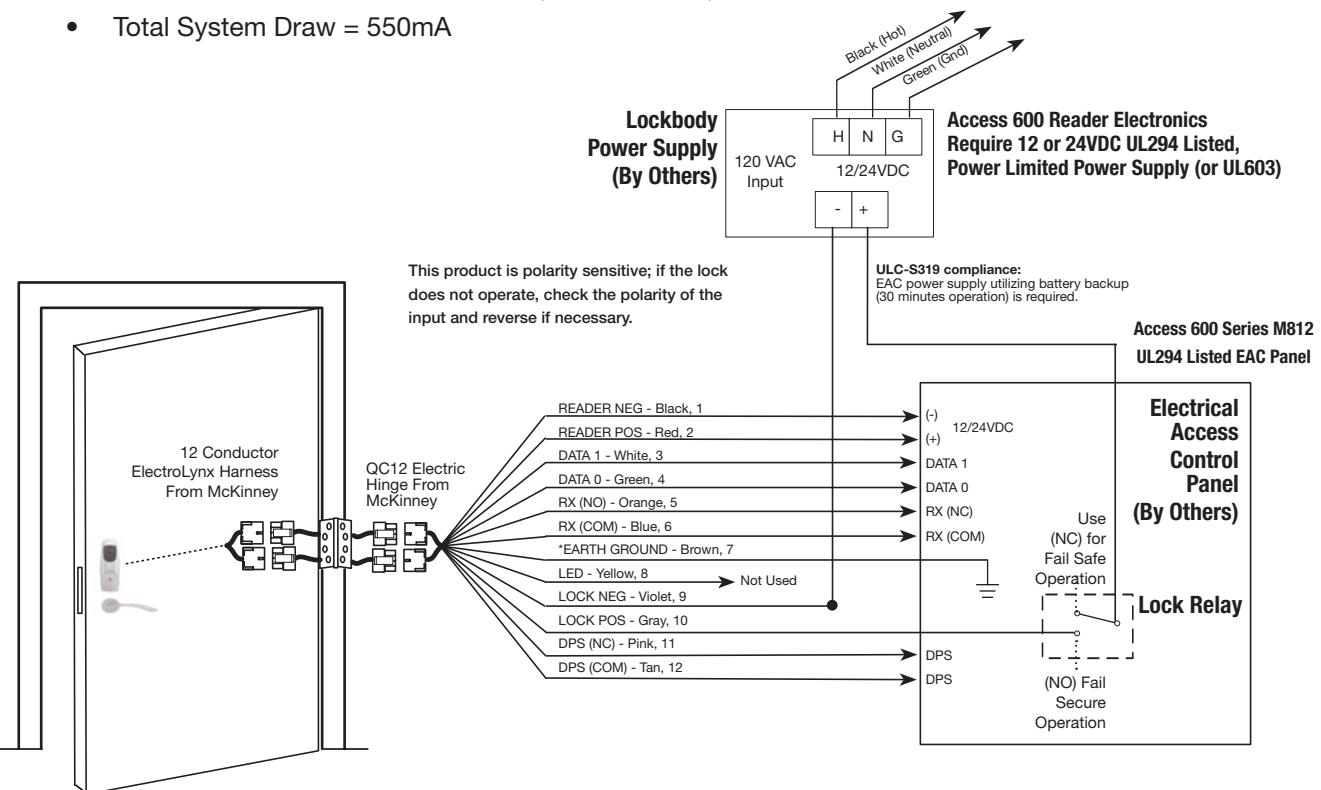

*IMPORTANT: Pin 7 must be tied to ground in the access control panel.
Failure to follow proper ESD safe grounding procedures could lead to equipment failure.
NOTE:
If your lock is configured with End of Line Resistors, reference instruction sheet FM406 for the wiring of RX & DPS outputs.

7) Installation Instructions
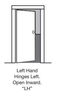
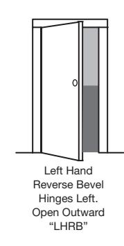
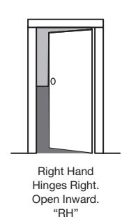
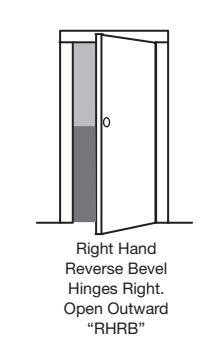
1. Verify Hand and Bevel of door.
Illustrations shown are as viewed from the outside or secure side of opening.
2. Prep door according to supplied door marker (FM293).
For door manufacture templates visit www.corbinrusswin.com and reference template # T31070.
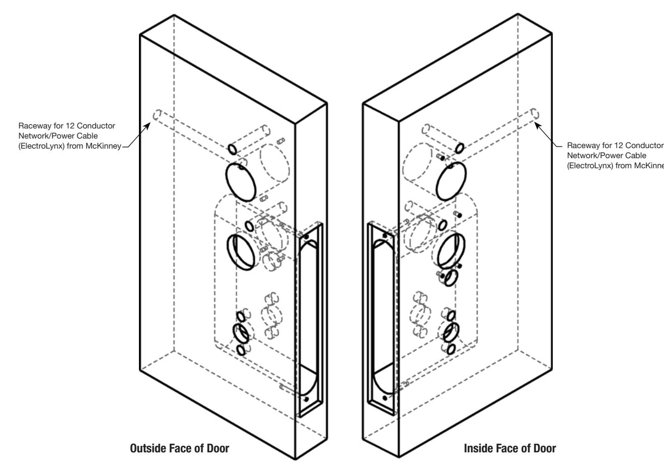
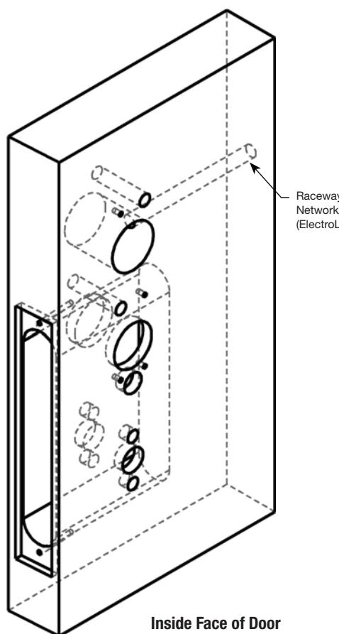
Network/Power Cable (ElectroLynx) from McKinney

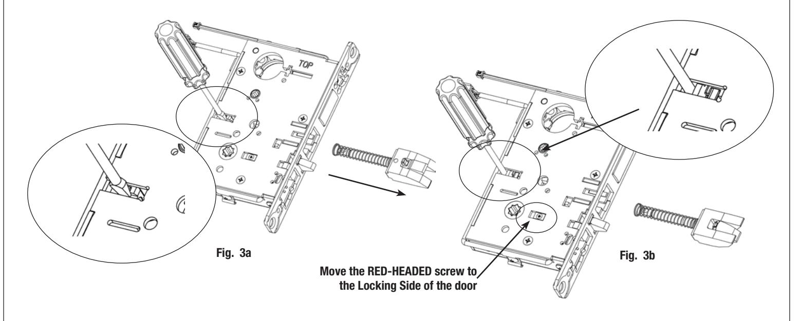
3. Handing of Lock Body:
If necessary re-hand latch and move RED locking screw to side of lockbody to side of lock body to be locked:
- a. Push in latch while gently pushing on catch plate with screwdriver (Fig. 3a).
- b. Release latch and remove from lock body.
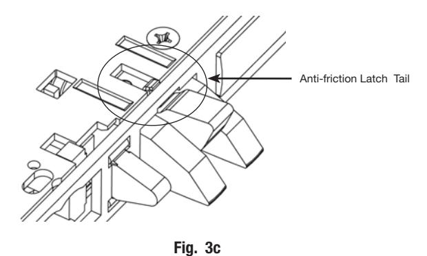
- c. Turn over latch and re-install in lock body; Be sure anti-friction latch tail hooks into front (Fig. 3c).
- d. Hold screwdriver behind tail socket while pushing in latch. Push latch until 'click' is heard (Fig. 3b). Note: Pull on latch to make sure it is secure.
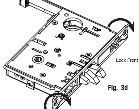
- e. Rotate lock front to match bevel of door by inserting screwdriver into lock mounting holes and twisting (Fig. 3d).

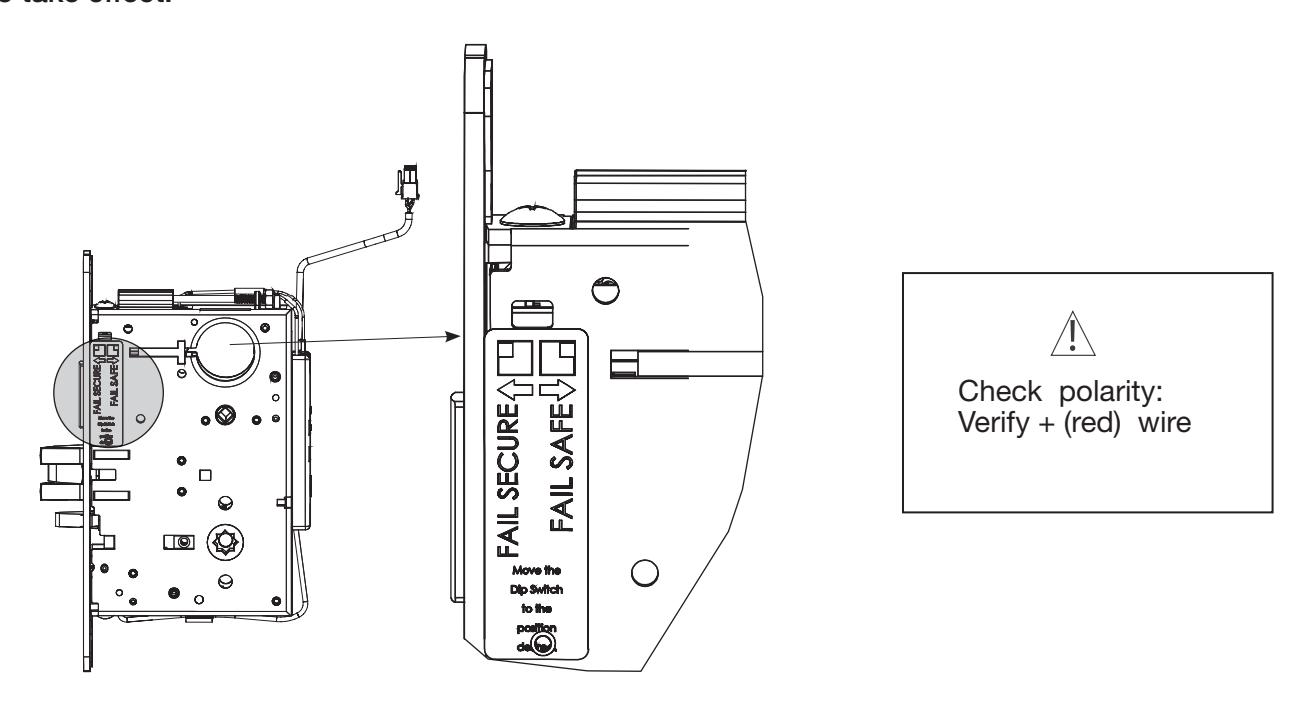
4. Configuring the Fail Safe/Fail Secure and RX* DIP switch settings:
Please note that the lock must be electrically cycled once in order for setting changes to take effect.
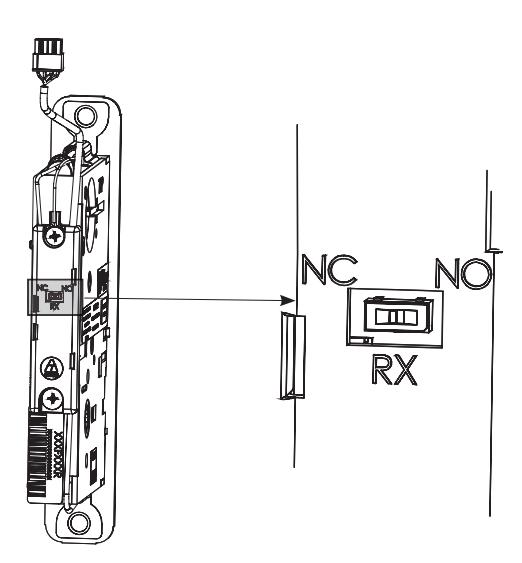
*RX output only configurable for locks with end-of-line resistance monitoring. Default is normally open.

5. Install Lock Body into Door:
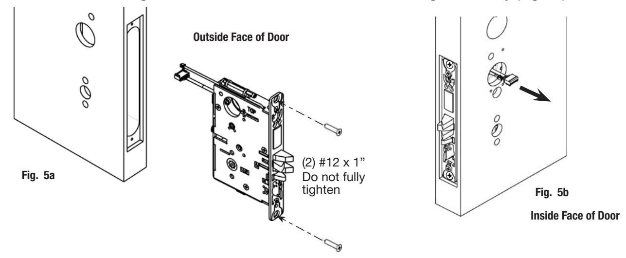
- a. Feed wires through 1-5/16" diameter hole on INSIDE of door while installing lock body (Fig. 5a).
- b. Pull wires through hole while inserting lockbody. DO NOT push wires back into cylinder hole (Fig. 5b). Important: Door must remain open during installation. Use door stop.
- c. Install, but do not tighten two #12 x 1" combination screws through lock body (Fig. 5a).
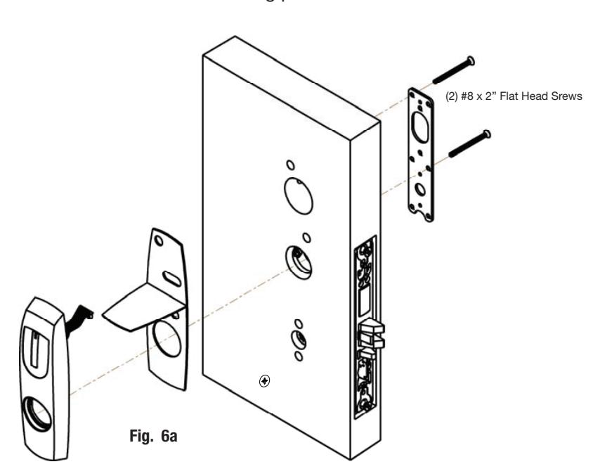
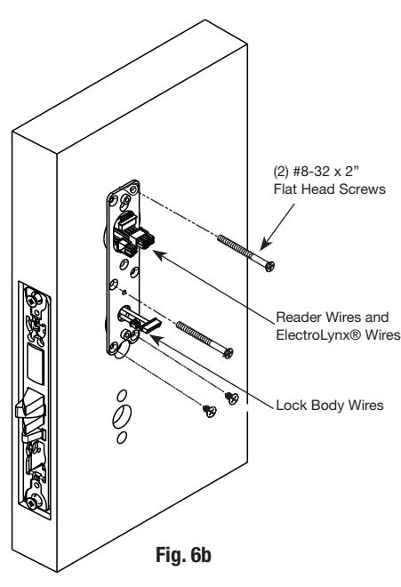
6. Install Outside Escutcheon and Inside Mounting Plate
NOTE: Feed mortise connectors through the corresponding hole on the mounting plate.
a. Attach the mounting plate using (2) 8-32 x 2" Phillips flat head undercut screws in the upper right and middle left positions of the mounting plate.

7. Install Cylinder:
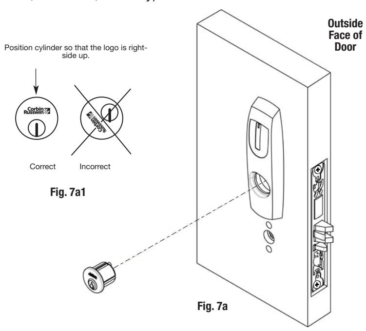
- a. Thread cylinder into lock body (Fig. 7a). Note: Make sure cylinder is oriented correctly (Fig. 7a1).
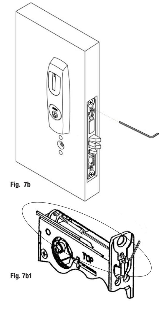
- b. Tighten cylinder clamp using 7/64" allen wrench provide (Fig. 7b and 7b1).
- c. Turn the key to make sure that lock functions correctly (latch, deadbolt, and key).
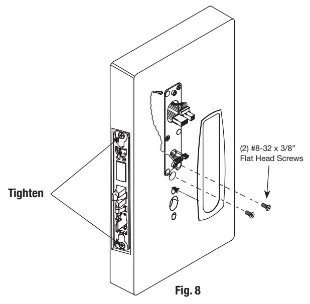
8A. Install Mounting Screws:
a. Install 2 surface mount (#8-32 x 3/8" combination screws) into pre-drilled 1/8" diameter holes (Fig. 8).
8B. Install Gasket (if necessary):
Remember to install the inside gasket when installing in an outdoor application.
Gasket fits snug around plate at top and sides, leaving room for the hole at the bottom.
Remove backing and place gasket on door (Fig. 8).

9. Installing Controller
Please follow these steps prior to installing inside escutcheon to prevent any damage caused by pinching wires:
a. Feed controller harness earth ground into and around behind rim of large upper hole of the mounting plate (Fig. 9a, b).
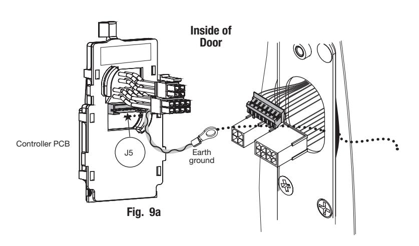
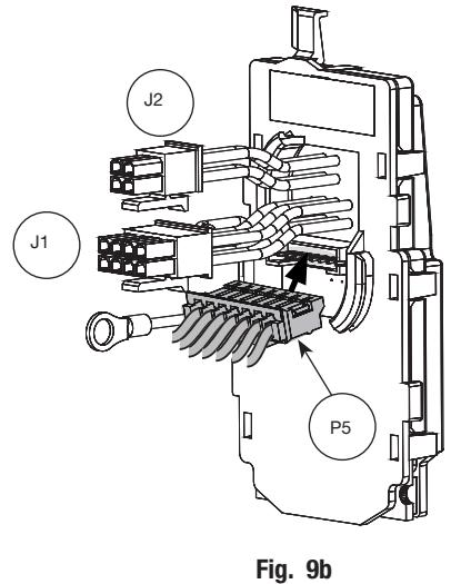
Fig. 9c
10. Connect ElectroLynx®
- a. Connect P5 (7 Pin Connector) from reader board to J5 on interior escutcheon PCB assembly (Fig. 9b).
- b. Connect ElectroLynx harness (4 and 8-pin) from door harness to ElectroLynx harness on interior PCB assembly (Fig. 9a-c).
NOTES: Neatly fold the wires into the remaining space to prevent pinching wires when mounting escutcheon.
Do not tuck extra mortise lock body wires back inside the lock body cylinder hole.
Connectors go on only one way.
Do not offset connector and be sure they are completely seated.
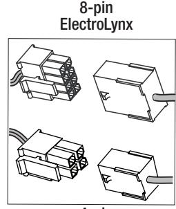
4-pin ElectroLynx
| PCB Layout - Wire Assignments - ElectroLynx Assembly (Molex) | ||||||||
|---|---|---|---|---|---|---|---|---|
| J2 | J1 | |||||||
| 1-Violet Lock Neg | 3-Pink | 1- Black | 3-White | 5-Orange | 7-Brown | |||
| (Solenoid, neg) | DPS (NC) | PWR NEG | DATA 1 | RX (NO) | EGND | |||
| 2-Gray Lock Pos | 4-Tan | 2-Red | 4-Green | 6-Blue | 8-Yellow | |||
| (Solenoid, pos) | DPS (COM) | PWR POS | DATA 0 | RX (COM) | LED | |||

11. Install Controller
Once wires are arranged, position controller at a rotated angle against the door, under earth ground wire.
- a. Press piece against door while turning clockwise (Fig. 11a).
- b. Twist into place, perpendicular with door (Fig. 11a, b).
- c. Position two-wire green/yellow ground wire ring terminal over hole for top left screw (Fig. 11b, c).
- d. Position green/yellow reader harness earth ground on top of two-wire ground ring and thread both with (1) 8-32 x 3/8" Phillips flat head undercut combo screw (Fig. 11c).
IMPORTANT: Note orientation of ground ring terminals in Fig. 11B-D.
e. Tighten securely.
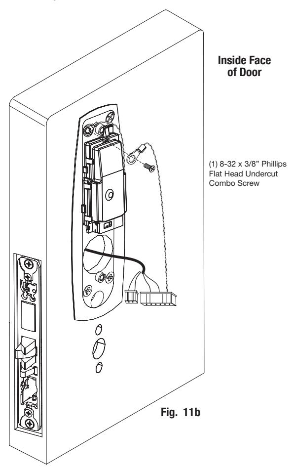
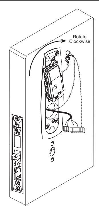
Fig. 11a

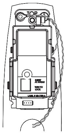
Fig. 11c

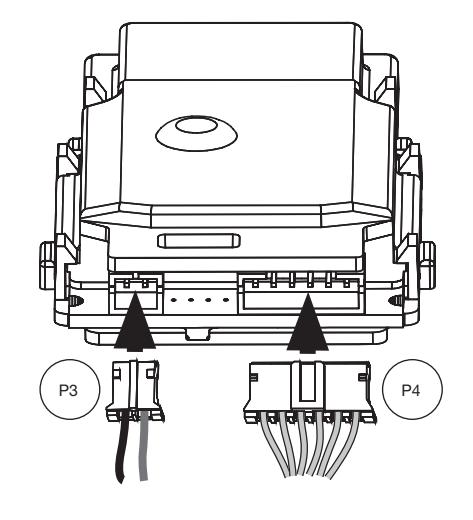
12. Connector Attachment (Controller)
- a. Connect P3 (2-pin connector) from lock body to J3 on module (Fig. 12).
- b. Connect P4 (6-pin connector) from lock body to J4 on module (Fig. 12).
Fig. 12
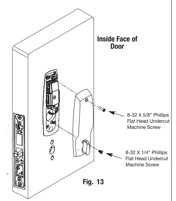
13. Inside Eschutcheon Assembly:
-
a. Tighten the inside escutcheon securely to the mounting plate with the Phillips flat head machine screws provided.
- Use the 8-32 x 5/8" for the top of the escutcheon and the 8-32 x 1/4" screws for the bottom of the escutcheon located under the turn lever.
- Remember the inside gasket must be used when installing in an outdoor application.
- b. Be sure the turn assembly is functional and, if equipped with a deadbolt, that the deadbolt functions properly.

7) Installation Instructions (Continued)
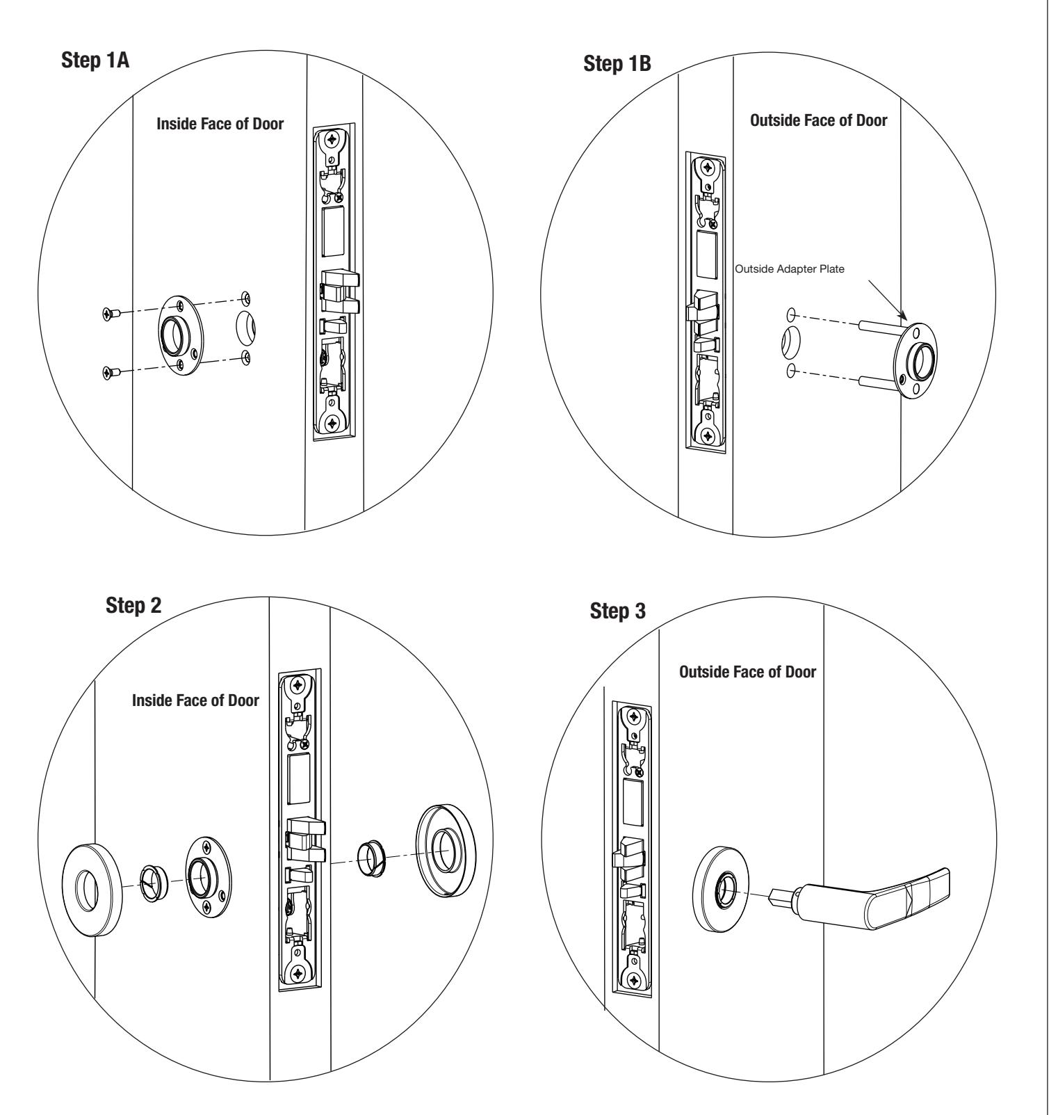
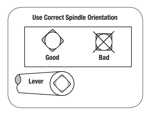
14a. Install Standard Lever Trim. Refer to next section (14b) on following pages for Muséo Trim:

7) Installation Instructions (Continued)
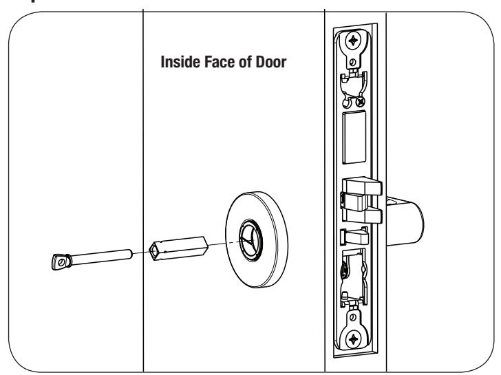
Step 4
Step 5
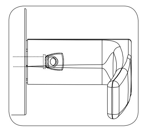
Adjustment bolt needs to be threaded in farther.
Align adjustment bolt with threaded hole in lever
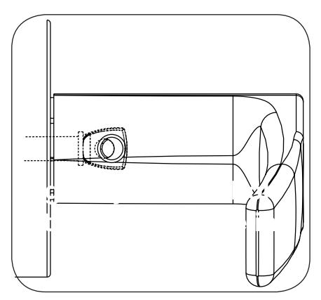
Adjustment bolt needs to be unthreaded.
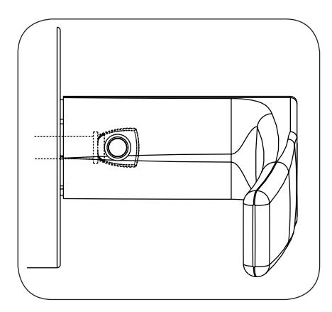
Adjustment bolt fully aligned.
Step 6
Notes:
- Unthread Adjustment Bolt approximately four turns for a good starting point (After being fully tightened)
- Make sure O/S lever is fully inserted into adapter plate before aligning adjustment bolt.
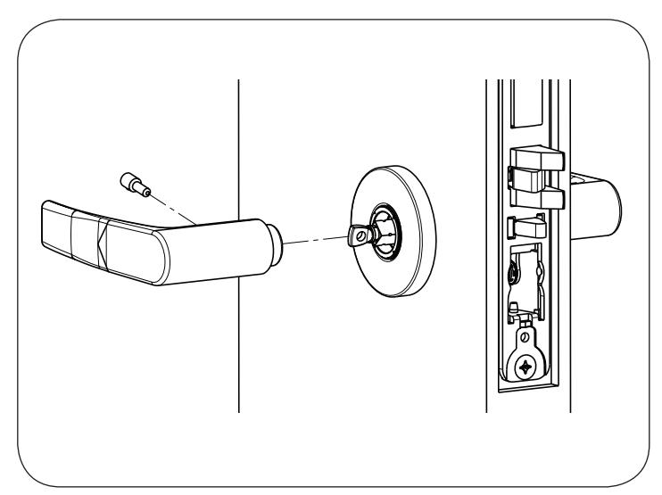

14b. Install Mus é o Trim:
Step 1
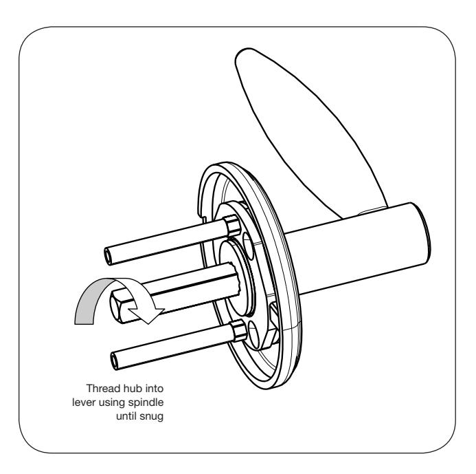
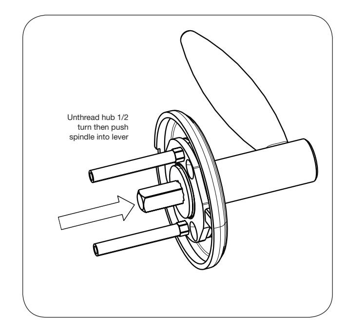
Step 2
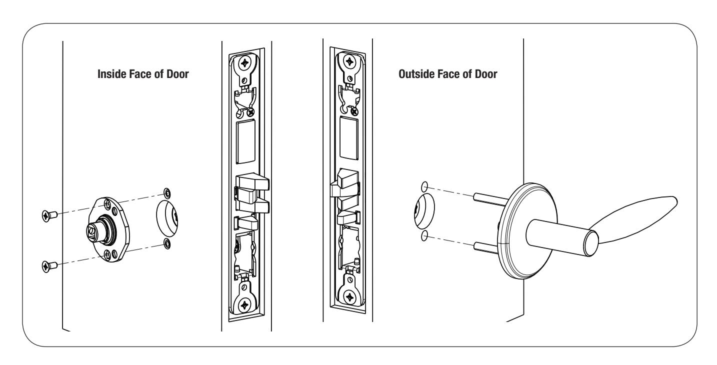

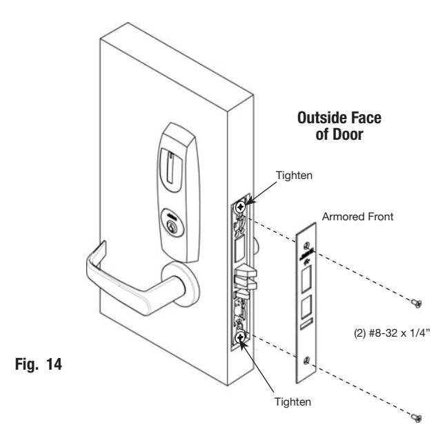
14c. Install Armored Front:
- a. Tighten (2) screws through lock body.
- b. Attach armored front with two #8-32 x ¼" screws (Fig. 14).

8) Operational Check
Mechanical Operational Check
Before closing door, test lock cylinder and inside lever function:
- a. Insert key into cylinder and rotate.
- b. Check to make sure that the key retracts the latch. The key should rotate freely.
- c. Check to make sure that the inside lever retracts the latch.
- d. Close door. Ensure that the latch fully extends into strike and does not bind.
Electrical Operational Check
Once electrical wiring has been completed follow these steps:
- a. Turn power "ON" at EAC panel.
- b. Verify reader LED is "ON" (red or green depending on reader configuration. Refer to reader LED configuration).
- c. Present proximity credential and verify LED and sounder activity.
- d. Verify that a valid card read at EAC Panel.
- e. Verify system operation so that when a credential is presented credential to the reader, the door unlocks.
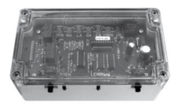
Wiegand Test Unit
The ASSA ABLOY Wiegand Test Unit verifies your installation in the field. The test unit checks for proper wiring, card reader data integrity, lock functionality including lock/unlock, door position status, and request-to-exit (REX) status.
In addition, this tool provides product demonstration abilities to highlight the product's features and capabilities.
| Feature | WT1 | WT2 |
|---|---|---|
|
12 or 24VDC solenoid
lock voltage adjustable |
X | X |
|
Operates as Fail Safe or
Fail Secure |
X | X |
|
"Learn" mode allows
testing of specific cards without programming at the panel level |
X | X |
|
Card reader data inte
grity is validated at test unit |
X | X |
| Works with SE LP10 | X | X |
|
Displays detailed
Wiegand data, including hexadecimal string and total bits received |
X | |
|
Displays measured end
of-line resistor values (if applicable) |
X |

Corbin Russwin 225 Episcopal Road Berlin, CT 06037 Phone: 800-543-3658 Fax: 800-447-6714 corbinrusswin.com
Copyright © 2017 Corbin Russwin, Inc., an ASSA ABLOY Group company. All rights reserved. Reproduction in whole or in part without the express written permission of Corbin Russwin, Inc. is prohibited. Patent pending and/or patent - www.assaabloydss.com/patents.