Corbin Russwin 500ET Trim for ED2000 Series Wide Stile Installation Instructions_FM651
Open the original PDF document
View PDFInstallation Instructions

500ET Series
ED2000 Exit Device Trim


All dimensions are in inches (mm) unless otherwise noted.
| ABBREVIATION | FASTENER DESCRIPTION |
|---|---|
| PPHMS | PHILLIPS PAN HEAD MACHINE SCREW |
| PTHMS | PHILLIPS TRUSS HEAD MACHINE SCREW |
WARNING
This product can expose you to lead which is known to the state of California to cause cancer and birth defects or other reproductive harm. For more information go to www. P65warnings.ca.gov.
For installation assistance contact Corbin Russwin 1-800-543-3658 • techsupport.corbinrusswin@assaabloy.com
Copyright © 2023, ASSA ABLOY Access and Egress Hardware Group, Inc. All rights reserved. Reproduction in whole or in part without the express written permission of ASSA ABLOY Access and Egress Hardware Group, Inc. is prohibited.

Attention Installer: Improper installation may result in damage to the product and void the factory warranty.
Exit Device Trim
500ET Series
Installation Instructions
DOOR
General Installation Instructions
- 1. Check box contents.
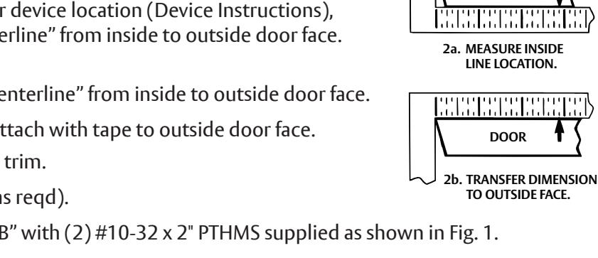
- 2. After marking door inside face for device location (Device Instructions), transfer "Vertical Reference Centerline" from inside to outside door face. Follow steps 2a and 2b, at right.
- 3. Transfer "Horizontal Reference Centerline" from inside to outside door face.
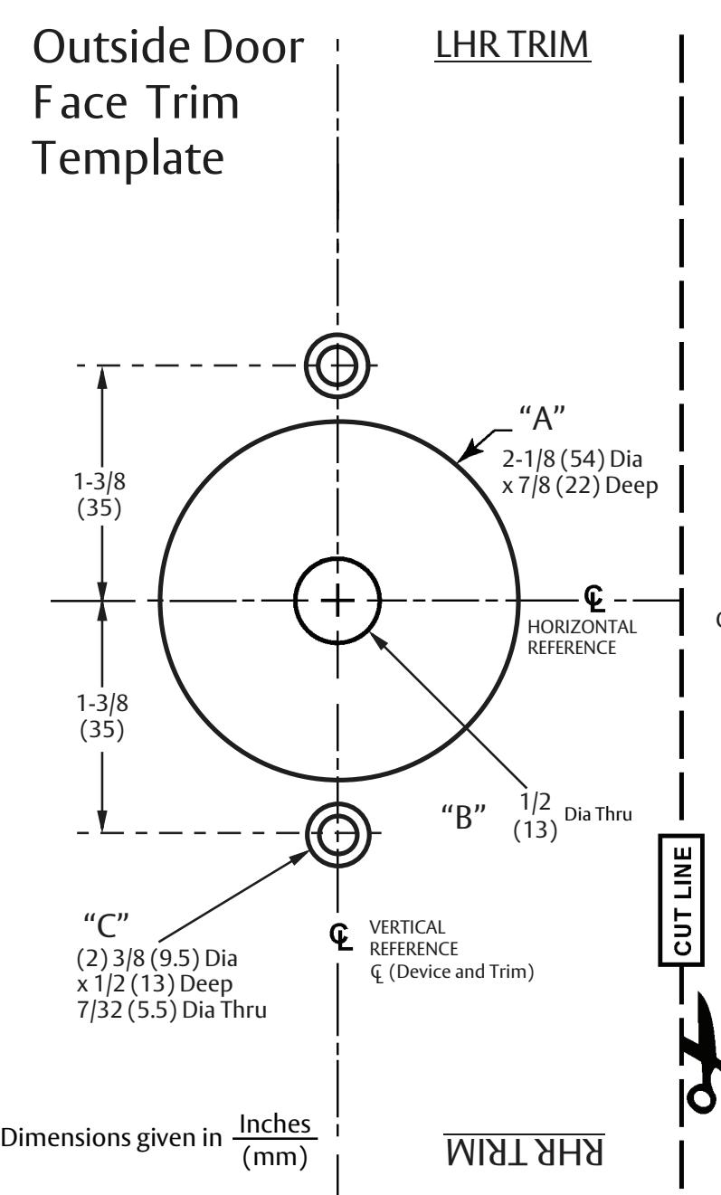
- 4. Orient and align trim template, attach with tape to outside door face.
- 5. Spot holes and prepare door for trim.
- 6. Adjust trim for door thickness (as reqd).
- 7. Mount trim to door thru holes "B" with (2) #10-32 x 2" PTHMS supplied as shown in Fig. 1.

Note : If installing dummy trim, continue as shown in device instructions.
- 8. If required, cut trim tailpiece so that it extends 5/16" from face of door (fi gure 2). Install device so that the tailpiece aligns with the cross hole of the cam slot (fi gure 1). Using 2 ¼-20 PPHMS (supplied with device), attach device to door through holes "A" (fi gure 1).
- 9. Continue as shown in device instructions.

NOTE: Measure from device mounting surface (door face or shim surface)
Figure 2: Taipiece Sizing
FM651 1/23
Exit Device Trim
500ET Series
Installation Instructions
Corbin Russwin ASSA ABLOY
Standard Cylinder
To re-key or exchange any of these cylinders, follow steps 3a or 3b shown below.
Lever Handle Removable
- 1. Insert key & rotate clockwise 45°.
- 2. Depress retainer with tool supplied.
- 3. Slide Lever off trim.
(Reverse steps to re-assemble.)

Figure 3a.
Interchangeable Core Cylinders
Trim levers are specific for the cylinder core used. Levers are not removable. To remove and install the cylinder use the control key supplied with the cylinder.

Figure 3b
Adjust Lock for Door Thickness (If Necessary)
Lock is packaged preadjusted for 1-3/4" (44mm) thick doors.) To adjust for a thicker door:.
- A. Remove (2) screws from outside rose plate.
- B. Slide outside rose away from lock body.
- C. Adjust rose plate to desired door thickness per illustration.
- D. Fasten outside rose to lock body with (2) screws.

1-3/4" Door __________________________________
FM651 1/23
Experience a safer and more open world

| TRIM | HOLES | |
|---|---|---|
|
510ET, 550ET,
555ET, 557ET |
A, B, C | |
|
For Holes Marked "X"
See Below |
||
|
METAL DOORS
Inside Face 5/16" (8) Dia. Outside Face 1/2" (13) Dia. |
||
| WOOD DOORS: 1/2" (13) Dia. Thru | ||
CAUTION: Office copiers and facsimile machines may change the size of a drawing and make the template inaccurate to use as a door marker If this is not the original template packed with the trim, use only the holes on the door (do not use template as a door marker).