Camden CX-PS30UL PS60UL 3 & 6 Amp Power Supply and Cabinet Installation Guide
Open the original PDF document
View PDF

M Series Multi-Output Access Control Power Supply Chargers
Installation Guide
Models Include:
- • AL300ULM AL400ULM - 2.5 amp @ 12VDC or 24VDC. - 3 amp @ 12VDC
- AL600ULM AL1012ULM - 6 amp @ 12VDC or 24VDC. 10 amp @ 12VDC.
-
AL1024ULM
- 10 amp @ 24VDC.
-
- or 4 amp @ 24VDC.
-
For a red enclosure, add an "R" suffix to the part # e.g. AL300ULMR
Overview:
These multi-output access control power supply/chargers are specifically designed for use with access control systems and accessories. These units convert a 115VAC / 60Hz input into five (5) individually protected 12VDC or 24VDC outputs (see specifications). Each output will route power to a variety of access control hardware devices including Mag Locks, Electric Strikes, Magnetic Door Holders, etc. These outputs will operate in both Fail-Safe and Fail-Secure modes. Controlled trigger input is achieved through normally open [NO] or normally closed [NC] supervised input or the polarity reversal from an FACP (Fire Alarm Control Panel). A form "C" dry output relay enables HVAC Shutdown, Elevator Recall or may be used to trigger auxiliary devices.
M Series Power Supply Configuration Reference Chart:
| Altorit del Turbet | Street AD | ation of | /& | / | - | izing districts | ||
|---|---|---|---|---|---|---|---|---|
| AL300ULM | 2.5 | 2.5 | 5 | Yes | 1.45 |
3.5 amp
250VAC |
(ŲL) | UL File # S4707 UL 1481 UL Listed for Power Supplies for Fire Protective Signaling Systems UL 294 UL Listed Access Control System Unit. UL 603 UL Listed for Burglar Alarms Systems. |
| AL400ULM | 4 | 3 | 5 | Yes | 1.9 |
3.5 amp
250VAC |
MEA Approved NYC Dept. of Buildings | UL 1069 UL Listed Hospital Signaling and Nurse Call Equipment. "Signal Equipment" Evaluated to CSA 22.2 N205-M1983 |
| AL600ULM | 6 | 6 | 5 | Yes | 2.5 |
3.5 amp
250VAC |
California | UL File # S4707 UL 1481 UL Listed for Protective Signaling Systems |
| AL1024ULM | - | 10 | 5 | Yes | 4.4 |
10 amp
250VAC |
State
Fire Marshal |
UL 294 UL Listed Access Control System Unit. "Signal Equipment" Evaluated to CSA 22.2 N205-M1983 |
| AL1012ULM | 10 | - | 5 | Yes | 1.9 |
3.5 amp
250VAC |
c UL us | UL File # BP617 UL 294 UL Listed Access Control System Unit. "Signal Equipment" Evaluated to CSA 22.2 N205-M1983 |
Specifications:
Input:
- Power input 115VAC 60Hz (see reference chart above).
- Fire Alarm Panel or Access Control System trigger inputs. [NO] or [NC] supervised trigger input and polarity reversal trigger input (4mA draw from FACP).
Output:
- Five (5) individual power limited class 2 outputs.
- Current limit is 2 amp @ 12VDC or 24VDC per output (12VDC only for AL1012ULM and 24VDC only for AL1024ULM).
- Filtered and electronically regulated outputs.
- Thermal and short circuit protection with auto reset.
- Overload protection.
- Output relay energizes when unit is triggered (form "C" contact rated 1 amp @ 28VDC).
Battery Backup:
- Built-in charger for sealed lead acid or gel type batteries.
- Automatic switch over to stand-by battery when AC fails.
-
AL300ULXB, AL400ULXB, AL600ULXB and AL1012ULXB (Power Supply Board) maximum charge current .7 amp.
AL1024ULXB (Power Supply Board) maximum chars
- AL1024ULXB (Power Supply Board) maximum charge current 3.6 amp).
- Zero voltage drop when switching over to battery backup.
- AL300ULM, AL400ULM and AL600ULM enclosures accommodate up to two (2) 12VDC/7AH batteries.
- AL1012ULM should be fitted with one (1) 12VDC/12AH battery.
- AL1024ULM enclosure accommodates up to two (2) 12VDC/12AH batteries.
- 2 - Mseries
Specifications (cont'd):
Visual Indicators:
- DC output LED indicator.
- LEDs indicate condition of power outputs.
- Power & input trigger LED's.
Supervision:
- AC fail supervision (form "C" contact).
- Low battery supervision (form "C" contact).
Supervision (cont'd):
- Battery presence supervision (form "C" contact).
- Power fail supervision relay (form "C" contact rated 1 amp @ 28VDC).
- Power supply is complete with enclosure, cam lock, transformer and battery leads.
Installation Instructions:
Wiring methods shall be in accordance with the National Electrical Code/NFPA 70/NFPA 72/ANSI, and with all local codes and authorities having jurisdiction. Product is intended for indoor use only.
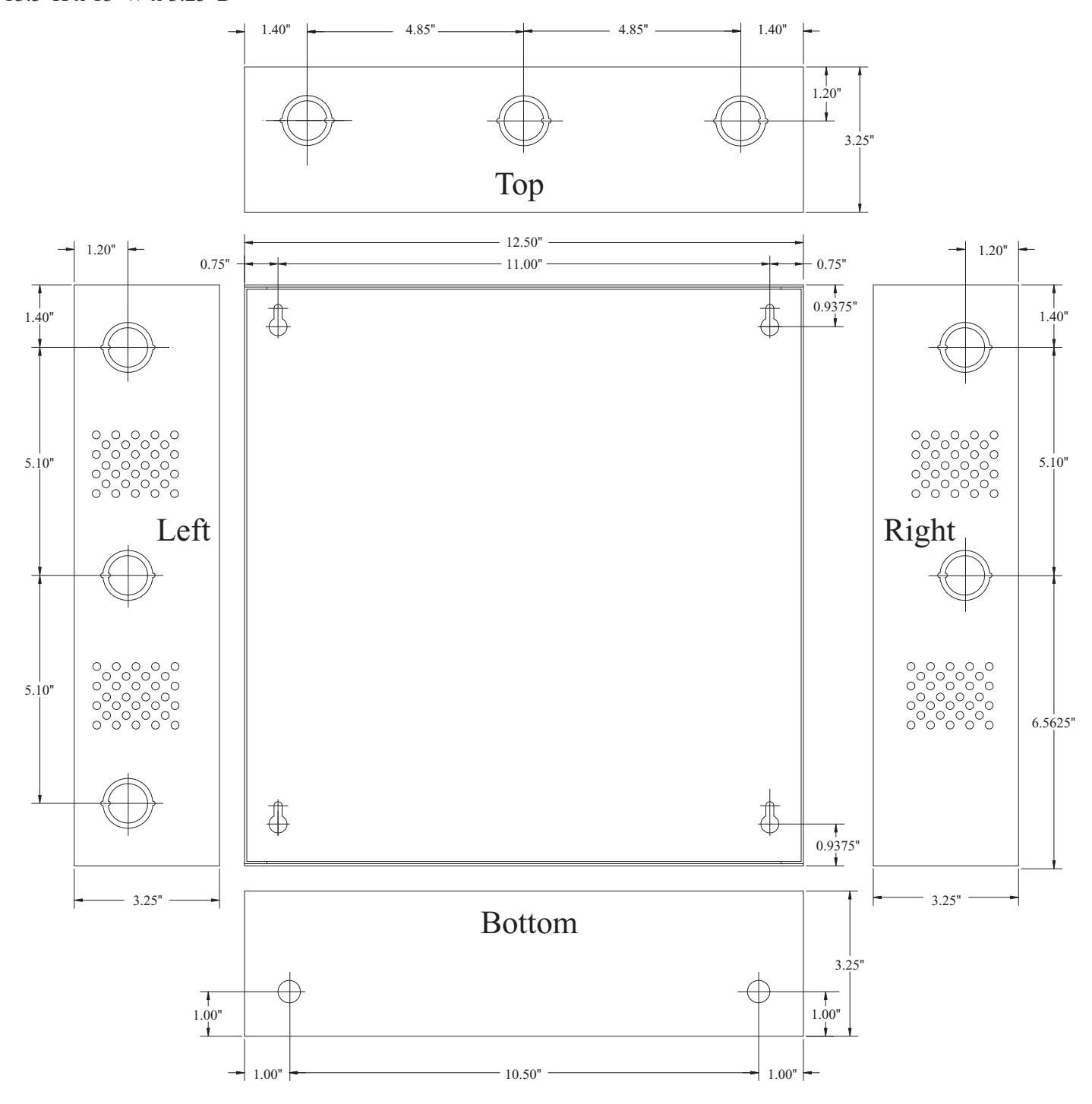
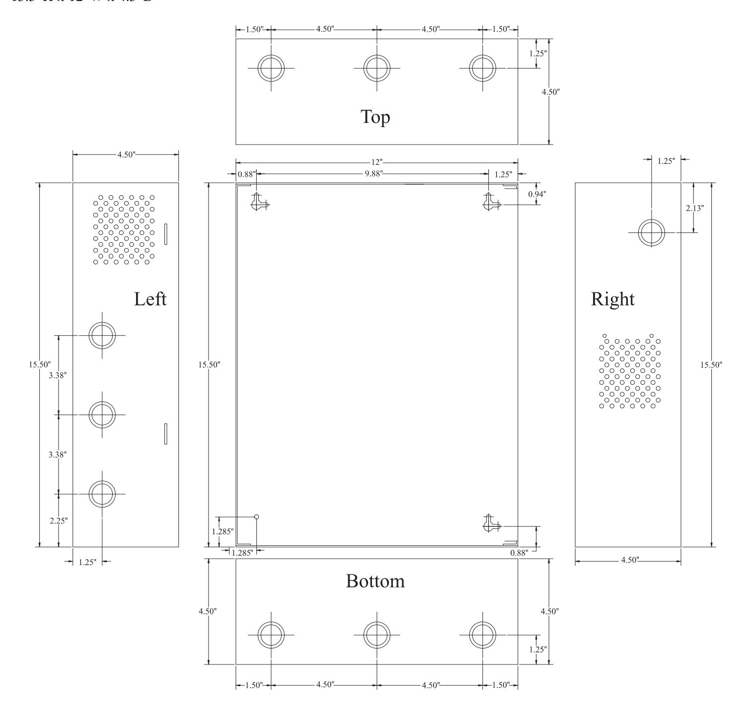
1. Mount unit in desired location. Mark and predrill holes in the wall to line up with the top two keyholes in the enclosure. Install two upper fasteners and screws in the wall with the screw heads protruding. Place the enclosure's upper keyholes over the two upper screws, level and secure. Mark the position of the lower two holes. Remove the enclosure. Drill the lower holes and install the three fasteners. Place the enclosure's upper keyholes over the two upper screws. Install the two lower screws and make sure to tighten all screws (Enclosure Dimensions, pg. 13,14) . Secure enclosure to earth ground. It is recommended to first review the following tables for screw terminals, switch selection and LED status indications. This will greatly facilitate installation hook-up. Carefully review:
Output Voltage & Stand-by Specifications (pg. 4) Terminal Identification Table (pg. 10) LED Diagnostics (pg. 9) Typical Application Diagrams (pgs. 11 & 12)
-
2.
Set output voltage:
- AL300ULM, AL400ULM and AL600ULM set desired DC output voltage by setting switch SW1 to the appropriate position on the power supply board ( Fig. 1B, pg. 5; Fig. 2B, pg. 6) . AL1012ULM is 12VDC only and AL1024ULM is 24VDC only. (Output Voltage and Stand-by Specification Charts below, pg. 4).
- 3. Secure green lead to earth ground. Connect AC power (115VAC 60Hz to terminals marked [L, G, N] on power supply board (Fig. 1, pg. 5; Fig. 2, pg. 6; Fig. 3, pg. 7; Fig. 4, pg. 8) . Use 18 AWG or larger for all power connections (Battery, DC output, AC input). Use 22 AWG to 18 AWG for power limited circuits (AC Fail/Low Battery reporting).
- 4. Measure output voltage before connecting devices. This helps avoid potential damage. Keep power limited wiring separate from non-power limited wiring (115VAC / 60Hz Input, Battery Wires). Minimum .25" spacing must be provided.
- 5. Connect Fail-Secure type locking hardware (e.g. door strikes and electronic dead bolts) positive leads to terminals marked [1 through 5 POS (+) DC OUTPUT (ALARM)] on MOM5 board and the negative leads to terminals marked [NEG 1 through NEG 5] on MOM5 board (Fig. 1, pg. 5; Fig. 2, pg. 6; Fig. 3, pg. 7; Fig. 4, pg. 8).
- 6. Connect Fail-Safe type locking hardware (e.g. mag locks, door strikes and door holders) positive leads to terminals marked [6 through 10 POS (+) DC OUTPUT (STAND-BY)] on MOM5 board and negative leads to terminals marked [NEG 1 through NEG 5] on MOM5 board (Fig. 1, pg. 5; Fig. 2, pg. 6; Fig. 3, pg. 7; Fig. 4, pg. 8).
-
7. To trigger the unit from a FACP connect signaling circuit of FACP to terminals marked [- INPUT +] on MOM5 board
(Fig. 1, pg. 5; Fig. 2, pg. 6; Fig. 3, pg. 7; Fig. 4, pg. 8).
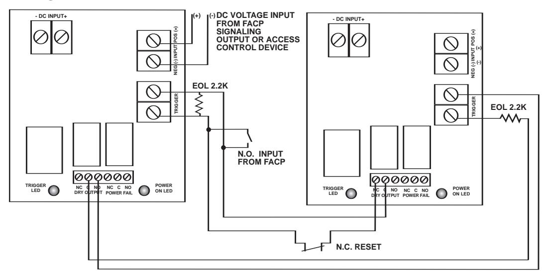
Polarity is shown in alarm condition. For latching fire alarm interface
(Figs. 8, 9, 10, pg. 12).
- Note: A 2.2K EOL must be installed across terminals marked [TRIGGER] on MOM5 board or the unit will remain in an alarm condition.
- 8. To trigger the unit using a supervised dry contact connect the 2.2K resistor in series for a NC trigger input and in parallel for [NO] trigger input (Fig. 5, pg. 11).
- 9. Connect auxiliary devices triggered by the unit to the terminals marked [DRY OUTPUT NO & C] on MOM5 board for normally open output or terminals marked [DRY OUTPUT NC & C] on MOM5 board for normally closed output (Fig. 1, pg. 5; Fig. 2, pg. 6; Fig. 3, pg. 7; Fig. 4, pg. 8). Note: This relay will energize when the unit is triggered.
- 10.For Access Control applications batteries are optional. When batteries are not used a loss of AC will result in the loss of output voltage. Batteries must be lead acid or gel type if used. Connect one (1) 12VDC battery to terminals marked [+ BAT -- ] on power supply board for 12VDC operation (Fig. 1, pg. 5; Fig. 2, pg. 6; Fig. 3, pg. 7; Fig. 4, pg. 8) . Use two (2) 12VDC batteries connected in series for 24VDC operation. (Battery leads included).
Mseries - 3 -
11.Connect supervisory trouble reporting devices to outputs marked [AC FAIL, LOW BAT] and [Power Fail] supervisory relay outputs marked [NO, C, NC] on power supply board (Fig. 1A, pg. 5; Fig. 2A, pg. 6; Fig. 3A, pg. 7; Fig. 4A, pg. 8). Use 22 AWG to 18 AWG for AC Fail & Low Battery reporting.
Note: When used in fire alarm, burglar alarm or access control applications, "AC Fail" relay must be used to provide a visual indication of AC power on.
12. Please insure that the cover is secured with the provided Key Lock.
Output Voltage and Stand-by Specification Charts:
AL300ULM
| Output |
Switch
Position |
4 hr. of Stand-by &
5 Minutes of Alarm |
24 hr. of Stand-by &
5 Minutes of Alarm |
60 hr. of Stand-by &
5 Minutes of Alarm |
|---|---|---|---|---|
| 12VDC / 40 AH Battery | Closed |
Stand-by = 2.5 amp
Alarm = 2.5 amp |
Stand-by = 1.0 amp
Alarm = 2.5 amp |
Stand-by = 300mA
Alarm = 2.5 amp |
| 24VDC / 12 AH Battery | Open |
Stand-by = 200mA
Alarm = 2.5 amp |
||
| 24VDC / 40 AH Battery | Open |
Stand-by = 2.5 amp
Alarm = 2.5 amp |
Stand-by = 1.0 amp
Alarm = 2.5 amp |
Stand-by = 300mA
Alarm = 2.5 amp |
AL400ULM
| Output |
Switch
Position |
4 hr. of Stand-by &
5 Minutes of Alarm |
24 hr. of Stand-by &
5 Minutes of Alarm |
60 hr. of Stand-by &
5 Minutes of Alarm |
|---|---|---|---|---|
| 12VDC / 40 AH Battery | Closed |
Stand-by = 4.0 amp
Alarm = 4.0 amp |
Stand-by = 1.0 amp
Alarm = 4.0 amp |
Stand-by = 300mA
Alarm = 4.0 amp |
| 24VDC / 12 AH Battery | Open |
Stand-by = 200mA
Alarm = 3.0 amp |
||
| 24VDC / 40 AH Battery | Open |
Stand-by = 3.0 amp
Alarm = 3.0 amp |
Stand-by = 1.0 amp
Alarm = 3.0 amp |
Stand-by = 300mA
Alarm = 3.0 amp |
AL600ULM
| Output |
Switch
Position |
4 hr. of Stand-by &
5 Minutes of Alarm |
24 hr. of Stand-by &
5 Minutes of Alarm |
60 hr. of Stand-by &
5 Minutes of Alarm |
|---|---|---|---|---|
| 12VDC / 40 AH Battery | Closed |
Stand-by = 6.0 amp
Alarm = 6.0 amp |
Stand-by = 1.0 amp
Alarm = 6.0 amp |
Stand-by = 300mA
Alarm = 6.0 amp |
| 24VDC / 12 AH Battery | Open |
Stand-by = 200mA
Alarm = 6.0 amp |
||
| 24VDC / 40 AH Battery | Open |
Stand-by = 6.0 amp
Alarm = 6.0 amp |
Stand-by = 1.0 amp
Alarm = 6.0 amp |
Stand-by = 300mA
Alarm = 6.0 amp |
AL1012ULM
| Output | |
|---|---|
| 12VDC / 12 AH Battery | 15 Minutes of Stand-by @ 10 amp |
AL1024ULM
| Output |
15 mins. Stand-by /
5 mins. Alarm |
4 hr. Stand-by /
5 mins. Alarm |
24 hr. Stand-by /
5 mins. Alarm |
60 hr. Stand-by /
5 mins. Alarm |
|---|---|---|---|---|
| 24VDC / 12 AH Battery | 7.7 amp / 9.7 amp | 1.2 amp / 9.7 amp | ||
| 24VDC / 65 AH Battery | 7.7 amp / 9.7 amp | 1.2 amp / 9.7 amp | 200mA / 9.7 amp |
- 4 - Mseries
Maintenance:
Unit should be tested at least once a year for the proper operation as follows:
Output Voltage Test: Under normal load conditions, the DC output voltage should be checked for proper voltage level (Output Voltage and Stand-by Specification Charts, pg. 4).
Battery Test: Under normal load conditions check that the battery is fully charged, check specified voltage at the battery terminals and at the board terminals marked [+ BAT-] to insure that there is no break in the battery connection wires.
Note: AL300ULXB, AL400ULXB, AL600ULXB and AL1012ULXB (Power Supply Board) maximum charge current is .7 amp.
AL1024ULXB (Power Supply Board) maximum charge current is 3.6 amp.
Expected battery life is 5 years, however it is recommended to change batteries within 4 years or less if necessary.
Fig. 1 AL300ULM AL400ULM
CAUTION: De-energize unit prior to servicing. For continued protection against risk of electric shock and fire hazard replace fuses with the same type and rating (see marking on the board). Replace fuse cover before energizing. Do not expose to rain or moisture.
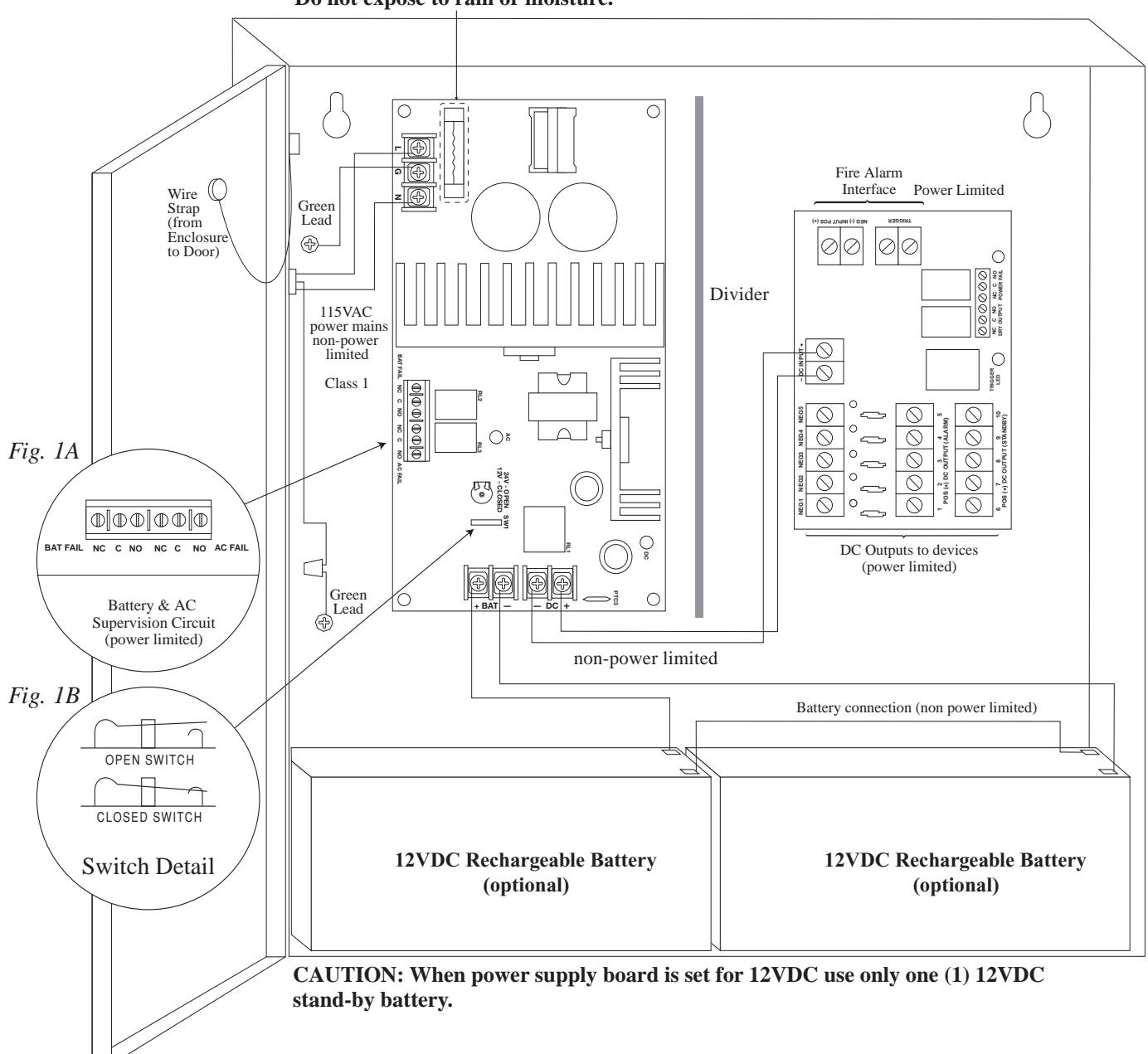
Keep power limited wiring separate from non-power limited. Use minimum .25" spacing.
Mseries - 5 -
CAUTION: De-energize unit prior to servicing. For continued protection against risk of electric shock and fire hazard replace fuses with the same type and rating (see marking on the board). Replace fuse cover before energizing. Do not expose to rain or moisture.
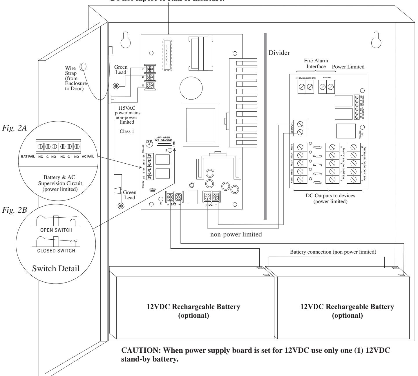
Keep power limited wiring separate from non-power limited. Use minimum .25" spacing.
- 6 - Mseries
Fig. 3 AL1012ULM
CAUTION: De-energize unit prior to servicing. For continued protection against risk of electric shock and fire hazard replace fuses with the same type and rating (see marking on the board). Replace fuse cover before energizing. Do not expose to rain or moisture.
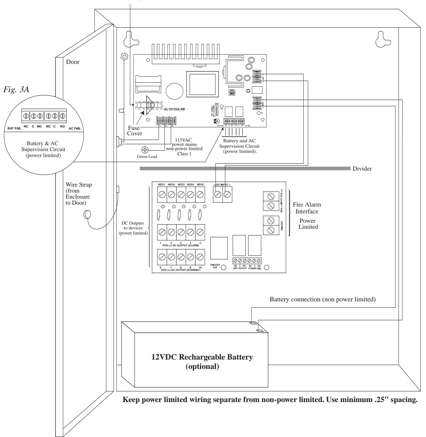
Mseries -7-
Fig. 4 AL1024ULM
CAUTION: De-energize unit prior to servicing. For continued protection against risk of electric shock and fire hazard replace fuses with the same type and rating (see marking on the board). Replace fuse cover before energizing. Battery & AC Supervision Circuit Do not expose to rain or moisture. (power limited) NO C NC NO C NC Battery and AC Supervision Circuit (power limited). Fig. 4A Door 0 115VAC power mains (4) non-power limited Green Lead Class 1 Divider Wire Strap (from Enclosure to Door) Fire Alarm 0 Interface Power DC Outputs to devices (power limited) Limited NC C NO NC C NO DRY OUTPUT POWER FAIL TRIGGER Battery connection (non power limited) 12VDC Rechargeable Battery 12VDC Rechargeable Battery (optional) (optional) Keep power limited wiring separate from non-power limited. Use minimum .25" spacing.
- 8 - Mseries
LED Diagnostics:
Power Supply Board
| LED | ||
|---|---|---|
| Red (DC) | Green (AC) | Power Supply Status |
| ON | ON | Normal operating condition. |
| ON | OFF | Loss of AC, Stand-by battery supplying power. |
| OFF | ON | No DC output. Short circuit or thermal overload condition. |
| OFF | OFF | No DC output. Loss of AC. Discharged battery. |
MOM5 - Output Module
| LED | ON | OFF |
|---|---|---|
| Power (Green) | Normal operation. | Power failure. |
| Trigger (Green) | Input is triggered (alarm condition). | No input trigger (non-alarm condition). |
| Outputs (Red) |
Output tripped due to a
short circuit or overload condition. |
Normal operation. |
Mseries - 9 -
Terminal Identification Tables:
Power Supply Board
|
Terminal
Legend |
Function/Description |
|---|---|
| L, G, N | Connect 115VAC 60Hz to these terminals: L to hot, N to neutral, G to ground. |
| - DC + |
AL300ULM - 12VDC/24VDC @ 2.5 amp to MOM5 board (power limited).
AL400ULM - 12VDC @ 4 amp or 24VDC @ 3 amp to MOM5 board (power limited). AL600ULM - 12VDC/24VDC @ 6 amp to MOM5 board (non-power limited). AL1012ULM - 12VDC @ 10 amp to MOM5 board (non-power limited). AL1024ULM - 24VDC @ 10 amp to MOM5 board (non-power limited). |
|
AC FAIL
NO, C, NC |
Indicates loss of AC power, e.g. connect to audible device or alarm panel. Relay
normally energized when AC power is present. Contact rating 1 amp @ 28VDC. AC or brownout fail is reported within 1 minute of event. To delay reporting of up to 6 hrs., cut "AC delay" jumper and reset power to unit. |
|
BAT FAIL
NO, C, NC |
Indicates low battery condition, e.g. connect to alarm panel. Relay normally
energized when DC power is present. Contact rating 1 amp @ 28VDC. A removed battery is reported within 5 minutes. Battery reconnection is reported within 1 minute. Low battery threshold: 12VDC output threshold set @ approximately 10.5VDC (N/A for AL1024ULM), 24VDC output threshold set @ approximately 21VDC. |
| + BAT - |
Stand-by battery connections. AL300ULXB, AL400ULXB and AL600ULXB (Power Supply
Board) maximum charge current is .7 amp. AL1024ULXB (Power Supply Board) maximum charge current is 3.6 amp. |
MOM5 - Output Module
| Terminal Legend | Function/Description |
|---|---|
| DC INPUT + | 12VDC or 24VDC from power supply. |
| TRIGGER |
Dry normally open [NO] or normally closed [NC] supervised (2.2K EOL resistor)
input trigger. A short or open circuit will transfer power from terminals marked [POS. (+) DC OUTPUT (STAND-BY)] to terminals marked [POS (+) DC OUTPUT (ALARM)]. |
| INPUT + |
Wet (5-30VDC) input trigger. Applying voltage to these terminals in the polarity shown
will transfer power from terminals marked [POS. (+) DC OUTPUT (STAND-BY)] to terminals marked [POS (+) DC OUTPUT (ALARM)] (e.g. fire alarm control panel indications circuit). |
| NEG 1 THRU NEG 5 | Supplies constant negative (-) voltage. |
|
POS (+) DC OUTPUT
(ALARM) 1-5 |
Supplies positive (+) voltage when dry trigger input or fire
alarm wet trigger input is applied. |
|
POS (+) DC OUTPUT
(STAND-BY) 6-10 |
Supplies positive (+) voltage in normal condition.
Power is removed when dry trigger input or fire alarm wet trigger input is applied. |
|
NC, C, NO
DRY OUTPUT |
When the MOM5 is triggered the terminals marked [C and NO] will open and the
terminals marked [C and NC] will close. This output is used to trigger auxiliary devices. (e.g. HVAC Shutdown, Elevator Recall etc.) Contact rating 1 amp @ 28VDC. |
|
NC, C, NO
POWER FAIL |
Form "C" contacts used for reporting no voltage is present at [ DC input +]
terminals. Under normal conditions, terminals marked [NO and C] are open, [NC and C] are closed. A loss of power causes terminals marked [NO and C] to close and [NC and C] to open. Contact rating 1 amp @ 28VDC. |
- 10 - Mseries
Typical Application Diagrams:
Fig. 5 MOM5 module shown with wet and/or dry normally closed trigger inputs (Non Letching):
mally closed trigger inputs (Non-Latching): DC VOLTAGE INPUT FROM FACP SIGNALING OUTPUT OR ACCESS CONTROL DEVICE EOL 2.2K N.C. INPUT FROM FACP OR ACCESS CONTROL DEVICE
MOM5 module shown with wet and/or dry normally open trigger inputs ( Non-Latching ):
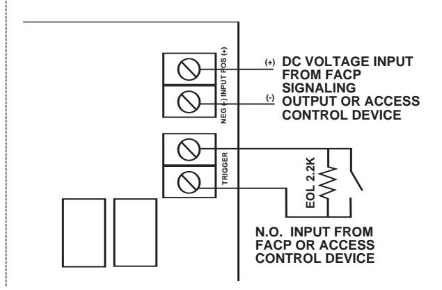
Fig. 6 - Two (2) or more MOM5 modules shown with wet and/or dry normally closed trigger inputs (Non-Latching):
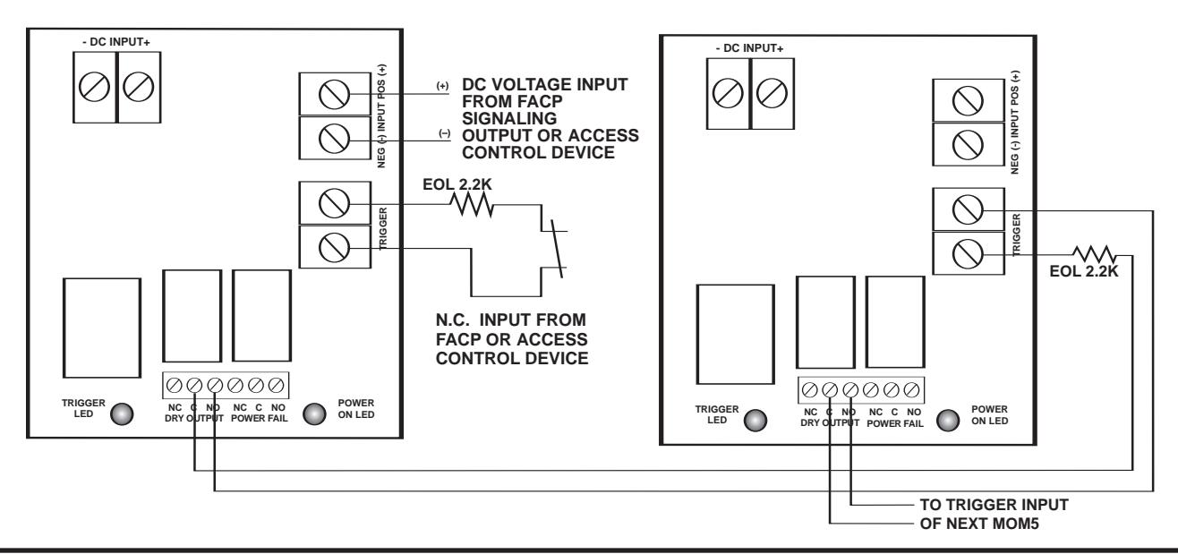
Fig. 7 - Two (2) or more MOM5 modules shown with wet and/or dry normally open trigger inputs (Non-Latching):
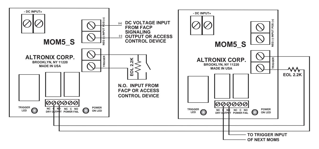
Mseries - 11 -
Typical Application Diagrams (cont'd.):
Fig. 8 MOM5 module shown with with wet and/or dry normally open fire alarm trigger inputs (Latching with Manual Reset):
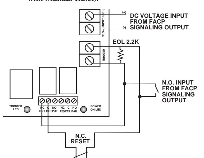
MOM5 module shown with with wet and/or dry normally closed fire alarm trigger inputs
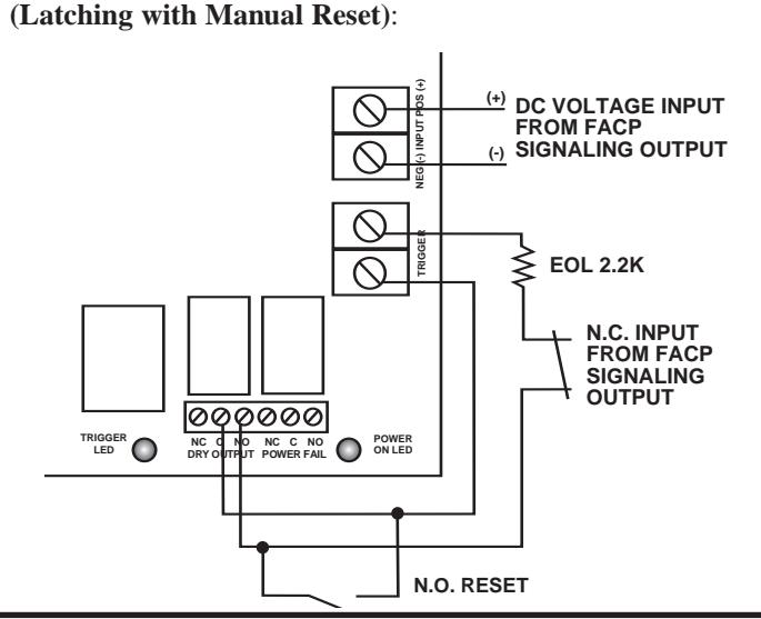
Fig. 9 - Two (2) MOM5 modules shown with wet and/or dry normally closed fire alarm trigger inputs (Latching with Manual Reset):
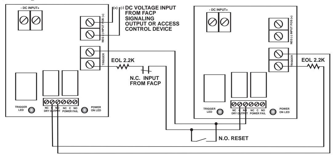
Fig. 10 - Two (2) MOM5 modules shown with wet and/or dry normally open fire alarm trigger inputs (Latching with Manual Reset):
- 12 - Mseries
Enclosure Dimensions:
- AL300ULM
- AL400ULM
- AL600ULM
13.5"H x 13"W x 3.25"D
Mseries - 13 -
Enclosure Dimensions:
- AL1012ULM
- AL1024ULM
15.5"H x 12"W x 4.5"D
- 14 - Mseries
Notes:
Mseries - 15 -
Notes:
Altronix is not responsible for any typographical errors.