Camden CX-PS 10UL 1 Amp Power Supply & Cabinet Instructions
Open the original PDF document
View PDF

CX-PS10UL Access Control Power Supply/Chargers
Rev. 022703
Overview:
CX-PS10UL Power Limited Power Supply/Charger that converts a 115VAC 50/60Hz input, into two individually PTC protected 12VDC or 24VDC outputs, (see specifications). It is intended for use in applications requiring UL Listing for Access Control (UL294) and applications requiring an interface with Fire Alarm Control Panels.
Specifications
Agency Listings:
- UL Listed U.S. and Canada Access Control (UL294).
- NFPA 101 (Life Safety).
Input:
• 115VAC 50/60 Hz, .6 amp.
Output:
- Two (2) 12VDC or 24VDC, class 2 rated power limited outputs.
- 1 amp total supply current @ 12VDC or 24VDC
- Filtered and electronically regulated output.*
Battery Backup:
- · Built-in charger for sealed lead acid or gel type batteries.
- Maximum charge current: 400mA.
- Automatic switch over to stand-by battery when AC fails.
• AC power and unit status indicator on the front panel.
• Normally Open [NO] trigger input.
• Supervised Fire Alarm Disconnect (Latching w/reset or Non-Latching).
Configurations:
Special Features:
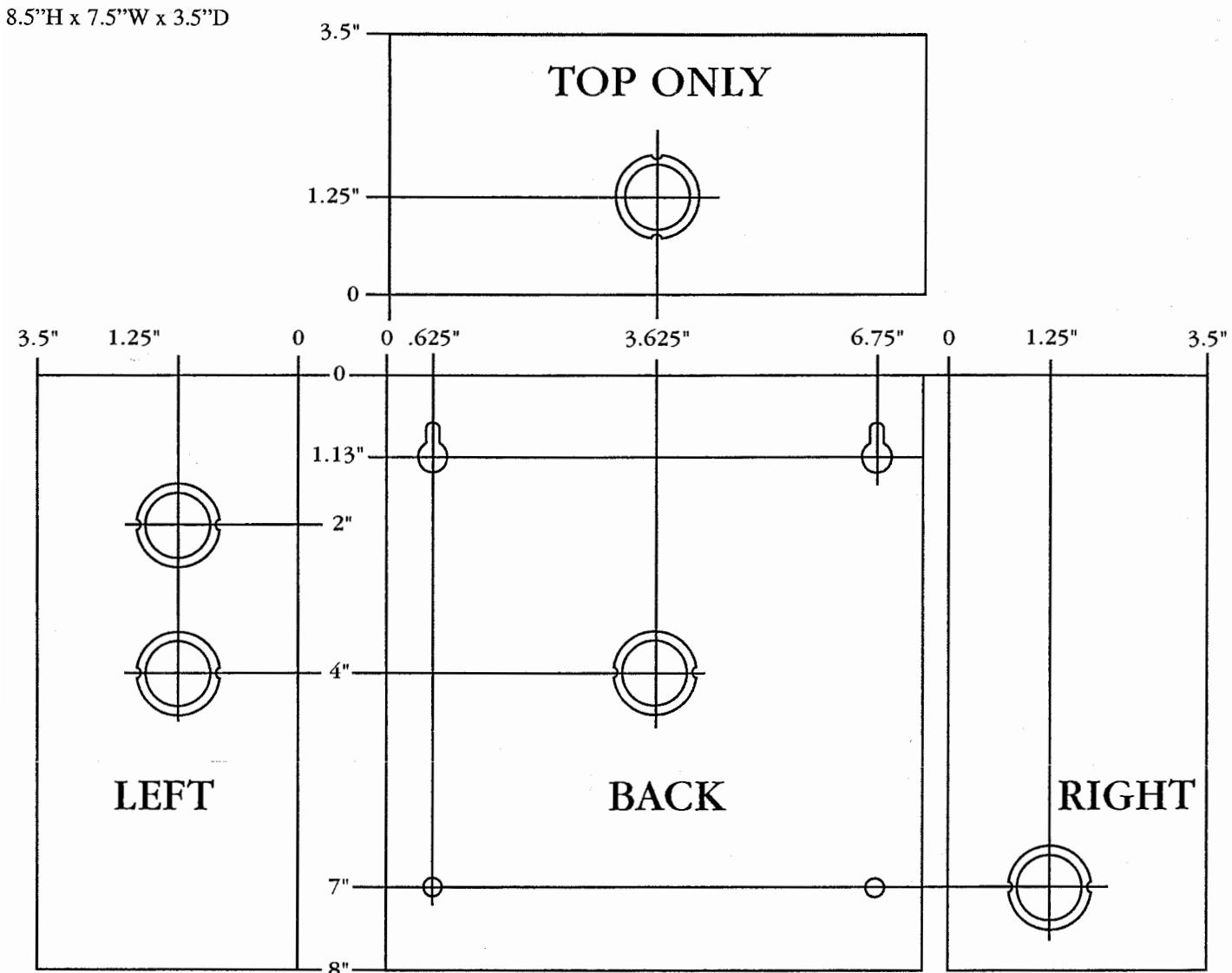
• Includes power supply, transformer and enclosure (8.5"H x 7.5"W x 3.5"D). Accomodates one (1) 12VDC/4AH battery.
*Note: When unit is powered by battery back up (AC Fail condition) the voltage range is 9.3V-13.2V and 19.55V-26.4V for 12 and 24 volt operation respectively.
Power Supply Output Specifications:
| Output VDC | Switch Position | Max. Stand-by Load DC | Max. Alarm Load DC | Battery (optional) |
|---|---|---|---|---|
| 12VDC | SW2 Open | 1 amp | 1 amp | 12VDC |
| 24VDC | SW2 Closed | 1 amp | 1 amp | 24VDC |
Stand-by Specifications:
| Output | 4 hr. of Stand-by & 5 Minutes of Alarm |
|---|---|
| 12VDC / 4AH Battery | .5 amp / 1 amp |
| 24VDC / 4 AH Battery | .5 amp / 1 amp |
| Output |
4 hr. of Stand-by &
5 Minutes of Alarm |
|---|---|
| 12VDC / 7 AH Battery | 1 amp / 1 amp |
| 24VDC / 7 AH Battery | 1 amp / 1 amp |
Installation Instructions:
The units should be installed in accordance with article 760 of The National Electrical Code and NFPA 72 as well as all applicable Local Codes.
See Terminal Identification Chart on page 2 for a description of each terminal function.
- 1. Install Power Supply Board into enclosure (Fig. 1 Board Installation Diagram, pg. 3).
- 2. Mount the unit in desired location.
- 3. Connect secondary (blue and yellow leads) from the transformer to the Power Supply Board terminals marked [XFMR] (Fig. 1 - Board Installation Diagram, pg. 3). Connect 115VAC 50/60Hz to the black and white flying leads of the transformer. Secure green wire lead to earth ground. Use 18 AWG or larger for all power connections (Battery, AC input, DC outputs). Use 22 AWG to 18 AWG for power limited circuits (Trigger inputs, Dry outputs, DC outputs).
Keep power limited wiring separate from non-power limited wiring (115VAC 50/60Hz Input, Battery Wires). Minimum .25" spacing must be provided.
4. Set the desired DC output voltage by setting switch SW2 to the appropriate position (Power Supply Output Specifications Table, pg. 1).
Note: It is important to measure output voltage before connecting devices. This helps avoid potential damage.
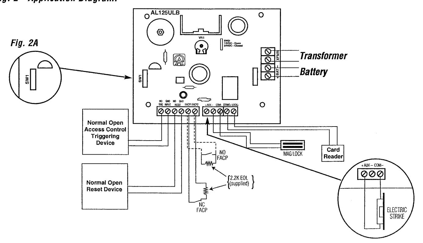
- 5. Connect Fail-Safe locking devices to the terminals marked [COM- and LOCK+]. Connect Fail-Secure locking devices to the terminals marked [COM- and STRIKE+] (Fig. 2 Application Diagram, pg. 3).
- 6. Connect normally open access control device (i.e. cardreader, request to exit device, access control system) to the terminals marked TRG INPUT [NO, GND] (Fig. 2 Application Diagram, pg. 3).
- 7. Connect FACP interface to the terminals marked [FACP1 and FACP2]. Wire the 2.2K resistor (supplied) in series for a normally closed input or in parallel for a normally open input (Fig. 2 Application Diagram, pg. 3). If required, set the latching FACP interface mode by closing SW1 (Fig. 2A Application Diagram, pg. 3), and connect a normally open reset device to the terminals marked RESET [NO, GND].
- 8. Connect battery to terminals marked [+ BAT -] (battery leads included). Use two (2) 12VDC batteries connected in series for 24VDC operation.
Note: For Access Control applications, batteries are optional. When batteries are not used a loss of AC will result in the loss of output voltage. When the use of stand-by batteries are desired, they must be lead acid or gel type.
Maintenance:
Unit should be tested at least once a year for the proper operation as follows:
Output Voltage Test: Under normal load conditions, the DC output voltage should be checked for proper voltage level (Power Supply Output Specifications Table, pg. 1).
Battery Test: Under normal load conditions check that the battery is fully charged, check specified voltage both at battery terminal and at the board terminals marked [- BAT +] to insure there is no break in the battery connection wires.
Note: Maximum charging current under discharges is 400mA.
Note: Expected battery life is 5 years, however it is recommended changing batteries in 4 years or less if needed.
Terminal Identification:
| Terminal Legend | Function/Description | |
|---|---|---|
| XFMR | Low voltage transformer connections. | |
| + AUX – | Aux power output terminals. These terminals will supply 12VDC or 24VDC, not affected by trigger, reset or fire alarm interface. | |
|
LOCK +
STRIKE + COM - |
Switched power output. Fail-Safe [LOCK+] supplies positive power when unit is not triggered and FACP interface is inactive. Fail-Secure [STRIKE+] supplies positive power when unit is triggered and/or fire alarm interface is activated. [COM-] supplies negative power. | |
|
FACP1
FACP2 |
Supervised by 2.2K end of line resistor FACP interface. Short or open will cause power to be dropped to terminal marked [LOCK+] and supply power to terminal marked [STRIKE+]. Condition can be maintained even after restoration of the circuit (latching mode). | |
|
TRG INPUT
NO, GND |
Short between these two terminals will cause power to be dropped to terminal marked [LOCK+] and supplied to terminal marked [STRIKE+]. | |
|
RESET
NO, GND |
Momentary short between these terminals would end latching FACP interface condition Feature active only if latching FACP is selected (SW1 closed). | |
| – BAT + | Stand-by battery connections. | |
LED Diagnostics:
| Red | Power Supply Status |
|---|---|
| ON | Normal function. |
| OFF | No DC output. |
| Slow Blink | Loss of AC. |
| Rapid Blink | Unit is triggered, awaiting reset. Fire alarm interface activated. |
Fig. 1 - Board Installation Diagram:
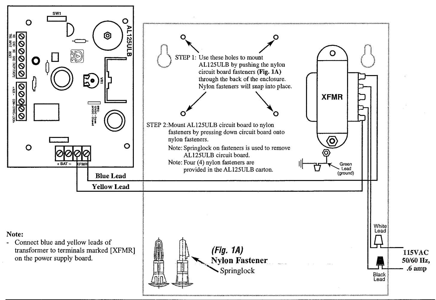
Fig. 2 - Application Diagram:
Enclosure Dimensions: