Camden CX-EMF-2 Multi Function Timer Installation Instructions
Open the original PDF document
View PDF

5502 Timberlea Blvd., Mississauga, ON L4W 2T7 Telephone: 905-366-3377 Fax: 905-366-3378
Toll-Free: 1-877-226-3369 Web: www.camdencontrols.com
EMF-2 / EMF-2m Multi-Function Timer
Installation Instructions
Ver. A1-001
MADE IN CANADA PAGE 1 OF 19
Section 1__________________
General Description
Camden model EMF-2 (EMF-2m or EMF-2ABM) is a microprocessor controlled multi-function relay. This all-in-one design replaces our previous models EMF-1, EMF-1m or EMF-1ABM.
The EMF-2 is designed for specialized applications such as ABM vestibules, one or two-door restrooms in shared-use facilities, 2 – 5 door airlocks, and secure man-traps.
Dip switches let you easily choose the mode, and the unit automatically programs the inputs, outputs and potentiometers accordingly.
Removable terminal strips simplify wiring chores, and all adjustments are conveniently located on one end of the case.
IMPORTANT : Do not apply power to the unit until you have read the instructions fully and made the required adjustments.
Section 2__________________
Installation
Mounting
The EMF-2 should be mounted in a clean dry location out of direct contact with the elements. Suitable locations include inside a metal box, operator header, or above a false ceiling. If placed on top of a header, ensure that unauthorized personnel cannot tamper with the unit.
If used in an Airlock or Mantrap application, the relay may be located at either door location, or, centrally to all doors. You must bring wiring from all door actuators to this unit (as well as the lock, operator, and door contact outputs as appropriate).
The EMF-2 is also available in an attractive lockable metal cabinet version (EMF-2m or EMF-2ABM), suitable for wall mounting.
Wiring
Wiring of this unit is dependant on the mode desired. Select your intended application, then proceed to the section indicated.
Note: Do not wire Safety devices to the EMF-2. If installed, wire your safety device directly to the operator control box.
I MPORTANT: Changes to the Mode and Out2 do not take effect until a power reset. It is therefore best to make these adjustments with the power turned off!
NOTE: We highly recommend the use of a regulated power supply when powering equipment for barrier-free washroom applications where the strike power may be maintained from a few minutes to many hours. We offer a low-cost board-only regulated power supply - CX-PS13 V2, which in turn can be powered from a small 24VAC transformer, (or the auxiliary power on the door control) and will supply clean, filtered & regulated 24VDC power for the strike and EMF-2.
APPLICATIONS & SET-UP INSTRUCTIONS:
ABM Vestibule Control (Mode 1) Proceed to section 3A on Page 3 1 Door Unsecured Restroom (Mode 2) Proceed to section 3B on Page 5 1 Door Secured Restroom (Mode 3) Proceed to section 3C on Page 7 2 Door Unsecured Restroom (Mode 4) Proceed to section 3D on Page 11 2 / 3 Door Airlock (w/ auto-crossing) (Mode 5) Proceed to section 3E on Page 13 2 - 5 Door Airlock (Mode 6) Proceed to section 3F on Page 15 2 Door Man-trap (Mode 7) Proceed to section 3G on Page 17 System Inspection Instructions Page 18
Technical Specifications, & Warranty Page 19
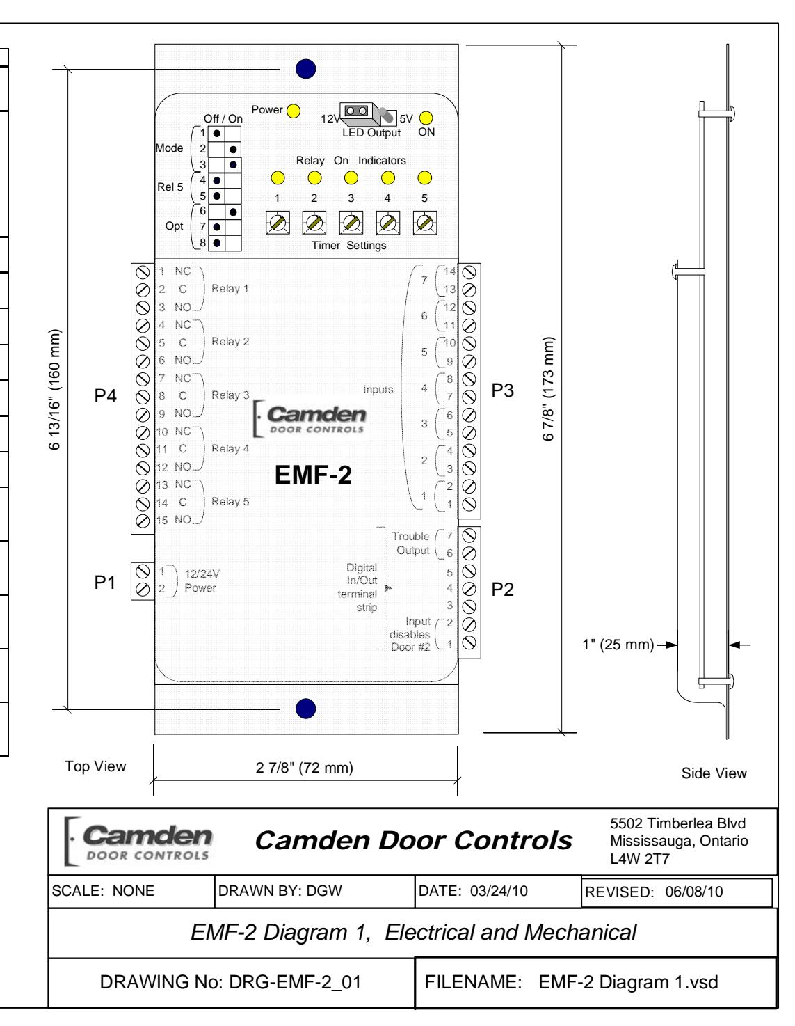
| Connector | Terminal | Label | Function |
|---|---|---|---|
| P1 | 1 | Power Input | 12/24 Volts AC/DC |
| 2 | Power Input | Non-polarized | |
| 1 | Ground | ||
| 2 | Blue (or Brown) | Cond Dooden | |
| 3 | N/C (or Yellow) | Card-Reader Input | |
| P2 | 4 | CR Power +5V | |
| 5 | Orange (output 1) |
(aka - Digital
Connector) |
|
| 6 | Output 2 | - Connector) | |
| 7 | Ground 2 | ||
| 1 | Dry 1 Input | Non noward Input 1 | |
| 2 | Dry 1 Input | Non-powered Input 1 | |
| 3 | Dry 2 Input | Non noward lanut 2 | |
| 4 | Dry 2 Input | Non-powered Input 2 | |
| 5 | Dry 3 Input | Non noward lanut 2 | |
| 6 | Dry 3 Input | Non-powered Input 3 | |
| Do | 7 | Dry 4 Input | New recovered leavet 4 |
| P3 | 8 | Dry 4 Input | Non-powered Input 4 |
| 9 | Dry 5 Input | Non noward Innut F | |
| 10 | Dry 5 Input | Non-powered Input 5 | |
| 11 | Dry 6 Input | Non noward Innut 6 | |
| 12 | Dry 6 Input | Non-powered Input 6 | |
| 13 | Dry 7 Input | Non noward Innut 7 | |
| 14 | Dry 7 Input | Non-powered Input 7 | |
| 1 | Relay 1 – NC | ||
| 2 | Relay 1 – COM | Form C | |
| 3 | Relay 1 – NO | ||
| P4 | 4 | Relay 2 – NC | |
| 5 | Relay 2 – COM | Form C | |
| 6 | Relay 2 – NO | ||
| 7 | Relay 3 – NC | ||
| 8 | Relay 3 – COM | Form C | |
| 9 | Relay 3 – NO | ||
| 10 | Relay 4 – NC | ||
| 11 | Relay 4 – COM | Form C | |
| 12 | Relay 4 – NO | ||
| 13 | Relay 5 – NC | ||
| 14 | Relay 5 – COM | Form C | |
| 15 | Relay 5 – NO |
NOTE: Pin 2 Connector. When connecting to Camden Card Reader in ABM Mode it is possible to read all cards by wiring the Blue wire to Pin 2, or only Cards beginning with a 4, 5, & 6 by wiring the Brown wire (Data) to Pin 2, and the yellow wire (Clock) to pin 3.
RELAY 5 CHART To have Relay 5 shadow another relay, set dipswitch as shown at right
|
Dip
4 |
Dip
5 |
= | |
| FF | OFF | 1 | |
| NC | OFF | 2 | |
| FF | ON | 3 | |
| NC | ON | 4 | |
Section 3A
Set-up Instructions ABM Vestibule Controller (Mode 1)
The EMF-2 is a compact unit designed to interface an automatic door operator with a card reader and lock system such as those used on banks.
When in "Day Mode" the strike is retracted (manually, or electrically) and the card reader is out of the circuit. Pressing either exterior or interior wall switch will activate the door operator.
When the EMF-2 is switched to "Night Mode" the electric strike is energized (door is locked), and the exterior activator (ie - wall switch) is removed from the circuit. When a valid card is inserted, the strike unlocks immediately, and the exterior switch is put back into the circuit for an adjustable period, so that if pushed by the user, it will open the door automatically. The inside switch will unlock and open the door at all times.
A new feature of the EMF-2 is the ability to add an "Emergency - Push-to-Lock" switch near the ATM machine that when activated "locks out" the card reader input in order to afford the user extra security. Opening the door from the inside resets the system. (The system will also reset automatically after 10 minutes.)
Model EMF-2 ABM provides for a lockable cabinet to house the relay, c/w two lighted push-button switches – one to turn the relay power ON or OFF , and the other to select DAY or NITE modes.
Step 1
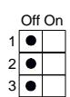
Select MODE 1 via the first 3 positions of the dip switch as shown below:
See Diagram 1 for location of dipswitch, connectors, & potentiometers.
Step2 Dip switch Options
Push dipswitch #6 ON , for a continuous duty strike, which is to be energized during "Day Mode". If using an intermittent duty strike and/or the latch is to be mechanically retracted during "Day Mode", then leave switch #6 OFF .
IMPORTANT: Any changes Mode selector or Out2 settings <u>must be made with power off! </u>
pr. . . . . . . . . . . . . . . . . . .
Step 3 Connections
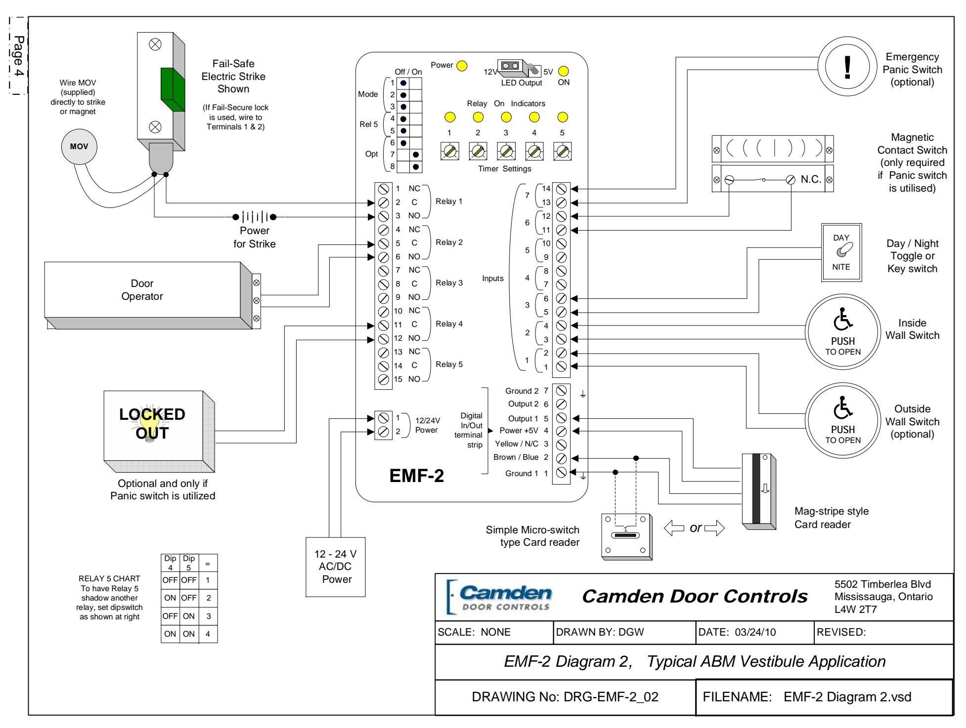
Refer to Diagram 2 (next page) for the following connections.
Wire all input connections to the (removable) Input terminal strip (numbered 1 - 14). Firmly re-insert connector if removed.
Next, make your wiring connections to the Relay Output strip (numbered 1 - 15). Note: Relay 4 is not used in this application. Re-insert connector.
If you are using this system with our Model #51T2B card reader – then refer to the 7-pin Digital I/O strip , and make wiring connections as per the respective card-reader wiring diagram.
If using our model #ECI-210, or another type of card reader, or dry contact - wire to terminals 1 & 2 of the Digital I/O strip . (Re-insert connector firmly if removed.)
Finally, connect 12 or 24 Volt AC or DC supply to terminals 1 & 2 of the 2-pin Power Connector. (The terminals are not polarity sensitive).
Step 4 Adjustments
In this application, you will use pots # 1 - 4. (Pot 5 has no effect.
| Timer 1 | Strike Delay-on-Release |
|---|---|
| Timer 2 | Operator Delay-on-activate |
| Timer 3 | Operator Delay-on-release |
| Timer 4 | Exterior Switch enable time |
Apply power to door operator, EMF-2, and any applicable activating devices (ie – card-reader). Observe the RED Power LED on the unit. It should be lit. If not, re-confirm proper voltage connections.
Turn key switch (Input #3) to "Night Mode". (Night mode via an open contact , Day mode via closed ).
Activate interior switch. Door should unlock and open. Adjust potentiometers # 1, 2 & 3 for desired operating times.
Activate exterior switch. Door should remain closed and locked. Now activate the card reader input. The door should unlock. Adjust Timer 1 for sufficient time on the strike.
When the card reader is activated, the exterior switch is "put into the circuit" for a limited time. This time is adjustable from 1 - 30 seconds via pot # 4.
Re-activate the card reader, and within the time frame, press the exterior switch. The door should now open.
Turn the Key switch (or other type switch) to "Day Mode". If the strike is to be dogged back mechanically, then do so. If it is to be powered all day long, then confirm that it is powered and released.
Now both the interior and exterior switches will open the door when activated. The card-reader has no effect on operation (it has been electronically deactivated).
A new option on the EMF-2 is the provision for an emergency " Lock Down " switch to be added. This momentary contact switch only functions in night mode. This test will take two persons – one to depress the switch inside, and another person outside to confirm the card-reader input has been disabled. Opening the door from the inside (either manually or automatically) will reset the system (a N/C magnetic door contact switch is required).
Once the desired operation is achieved, proceed to Section 4, for System Inspection Instructions .
Section 3B________________
Set-up Instructions Unsecured Restroom (Mode 2)
This application is a shared-use single (normally unlocked) restroom door in facilities such as nursing homes, hospitals, shopping malls, etc. The relay provides control of the lock, operator, and switches, to provide the utmost in flexibility, safety for the occupants, yet still be easy to install and program.
The door is opened automatically by pressing the exterior wall switch. Once the door has closed, pressing the "Push to Lock" button inside then locks the door – the strike is energized, and the exterior switch is removed from the circuit. To exit the restroom, simply push the interior wall switch. The door unlocks, opens and resets the system. Should the door be opened manually, the magnetic contact switch will reset the system.
Unique to the EMF-2 is the emergency input, which allows a panic button to unlock, open the door (optional), and send an emergency signal for assistance. The output can be maintained or pulsed. As an added safety feature, the EMF-2 can be set to automatically reset (and unlock) after 15 minutes time.
Step 1
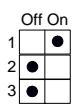
Select MODE 2 via the first 3 positions of the dipswitch as shown below:
See diagram 1 for location of dipswitch, connectors, & potentiometers.
IMPORTANT: Any changes Mode selector or Out2 settings must be made with power off!
Step 2 Dip switch Options
Push dipswitch #6 ON when you want the panic button to unlock the door and also open it . Leave switch #6 OFF to enable the panic button to unlock the door only but not open it.
Push dipswitch #7 ON , to enable the 15 minute timeout (reset) feature. Leave in OFF position if you do not want an automatic reset.
Use of Relay 5 is optional, and set according to dipswitches #4 & 5. (See diagram 1 for location). A common use in this mode would be to have Relay 5 follow the the lock relay and light an occupied sign. By default, Relay #5 follows Relay #1. Dipswitch # 8 is not used in this mode.
Step 3 Connections
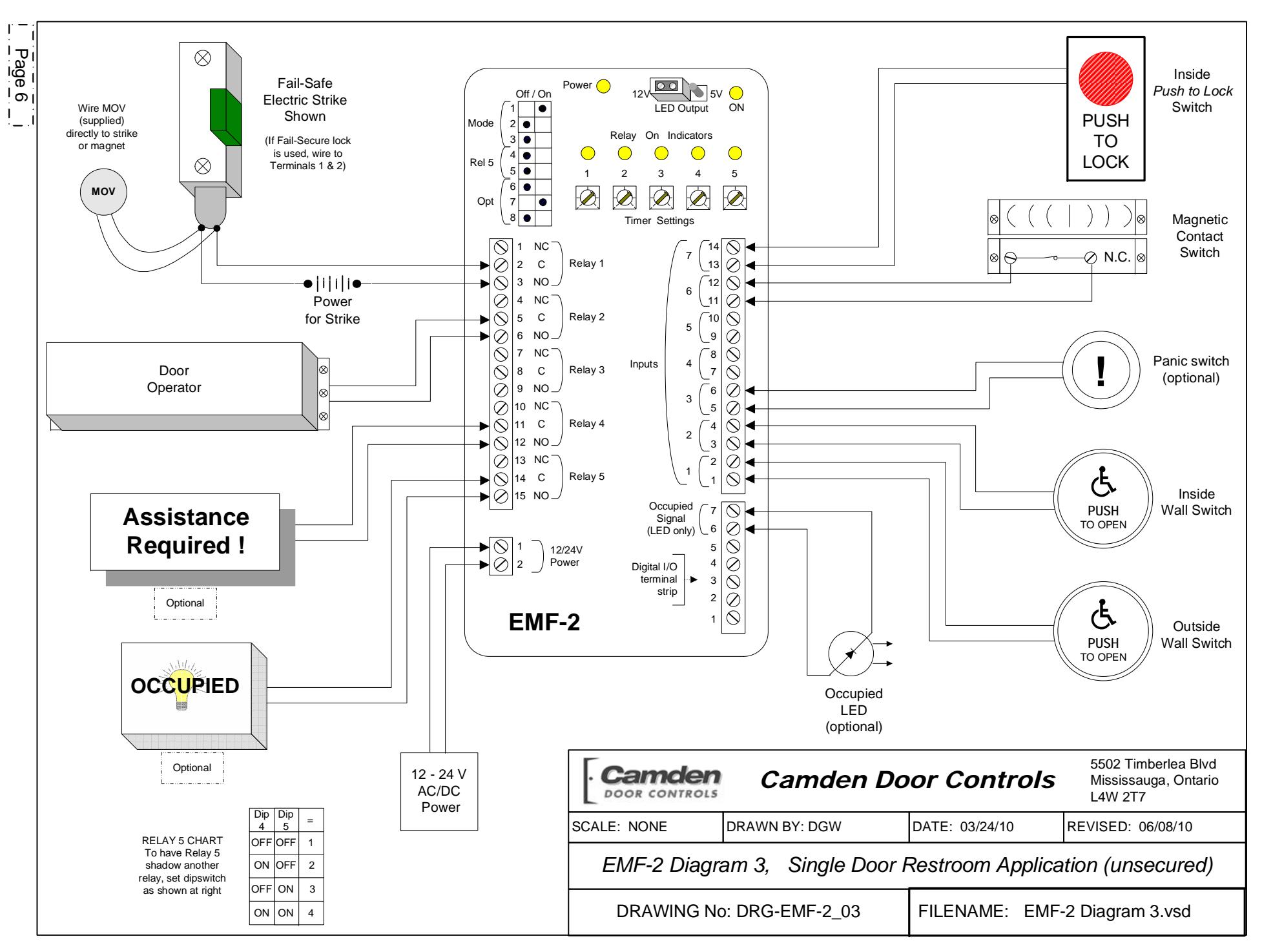
Refer to Diagram 3 (next page) for the following connections.
Wire all input connections to the (removable) Input terminal strip (numbered 1 - 14). Firmly re-insert connector if removed.
Next, make your connections to the Relay Output strip (numbered 1 – 15). (Relay 3 is not used in this application). Re-insert connector.
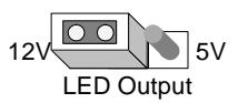
The 7-pin Digital I/O strip provides either 12V DC or 5V DC on Terminals 6 & 7 for lighting an " Occupied " LED. This output is present whenever the door is locked. Select output voltage using jumper as shown below:
Finally, connect 12 or 24 Volt AC or DC supply to terminals 1 & 2 of the 2-pin Power Connector. (The terminals are not polarity sensitive).
Step 4 Adjustments
In this application, you will use pots 2 – 5. Pot #1 has no effect.
| Timer 2 | Operator Delay-on-activate |
|---|---|
| Timer 3 | Operator Delay-on-release |
| Timer 4 | Panic Relay (#4) ON time |
| Timer 5 | Panic Relay (#4) OFF time |
| Note: If pot 5 is turned to zero, | |
relay will be on steady
Apply power to door operator, EMF-2, and all connected equipment (ie – strike, lights, etc). Observe the red Power LED on the unit, which should light. If not, re-confirm proper voltage and/or terminal strip connection.
Press the exterior wall switch. If the restroom is unoccupied the door will open automatically. Pot #2 adjusts the door hold-open time (up to 30 seconds). If the restroom is occupied and the lock button has been pressed, then the door will not open.
After entering the restroom, push the Lock button. The EMF-2 will energize the electric lock and remove the exterior Push switch from the circuit.
To exit the Restroom, two options are available:
- 1. To have the door unlock and open automatically, push the interior Wall switch. This will also reset the EMF-2 for the next person to use.
- 2. Manual Use. The door may also be used manually. To exit the restroom, turn the (lever) handle and pull (push) the door open. The magnet switch resets the unit into standby mode.
Emergency Panic Switch (optional)
Should an emergency occur, and assistance from the outside is required, the occupant can push a button or ribbon switch to signal the EMF-2. When activated, the EMF-2 will unlock the door (and optionally open the door). A maintaining type input is required to keep the door held open.
Further, Relay #4 is now activated, which can be used to signal for assistance, sound an alarm – whatever you choose. The installer can choose a continuous or pulsing output, depending on the settings of potentiometers # 4 & 5.
Emergency Time-out Feature
An added safety feature in the EMF-2 is the ability to automatically reset to standby mode after a fixed lock time of 15 minutes. The door will unlock, so that personnel may enter the restroom. This feature is engaged by turning dipswitch # 7 to ON position. If not desired, simply leave dipswitch 7 OFF .
Section 3C________________
Set-up Instructions Secured Restroom (Mode 3)
This application is a shared-use single (normally locked) restroom door in facilities such as nursing homes, hospitals, shopping malls, etc. The relay provides control of the lock, operator, and switches, to provide the utmost in facility security, safety for the occupants, yet still be easy to install and program.
In this application the door is normally locked whether occupied or not. It may be unlocked by Key-switch, keypad, or another credential. The EMF-2 can be configured to activate the door operator immediately, or after pressing the wall-switch within the (adjustable) time period. Once the door has closed, pressing the "Push to Lock" button removes the exterior keypad / key-switch from the circuit. The electric lock will pulse twice to let the user know that the door is secure, and an output is available to light an Occupied LED (s).
To exit the restroom, simply push the interior wall switch. The door unlocks, opens and resets the system. Should the door be opened manually, the magnetic contact switch will reset the system.
Unique to the EMF-2 is the emergency input, which allows a panic button to unlock, open the door (optional), and send an emergency signal for assistance. The output can be maintained or pulsed. As an added safety feature, the EMF-2 can be set to automatically reset (and unlock) after 15 minutes time.
Step 1
Select MODE 3 via the first 3 positions of the dip switch as shown below:
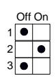
See diagram 1 for location of dipswitch, connectors, & potentiometers.
IMPORTANT: Any changes Mode selector or Out2 settings must be made with power off!
Step 2 Dip switch Options
Use of Relay 5 is optional, and set according to dipswitches #4 & 5.
Push dipswitch #6 ON when you want the panic button to unlock the door and also open it . Leave switch #6 OFF to enable the Panic button to unlock the door only but not open it.
Push dipswitch #7 ON , to enable the 15 minute timeout (reset) feature. Leave in OFF position if you do not want an automatic reset.
Dip switch # 8 can have the keypad unlock and open the door ( OFF ) or just unlock the door ( ON ). If set to ON , then an exterior wall-switch is required to open the door automatically.
Step 3 Connections
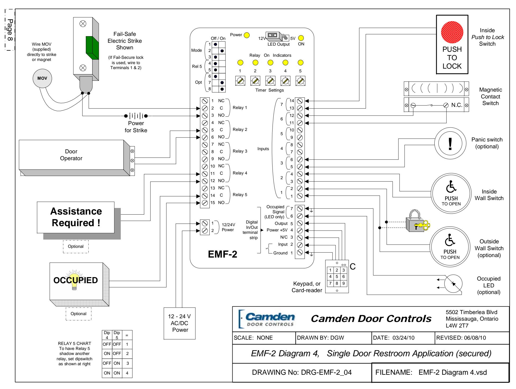
Refer to Diagram 4 (previous page) for the following connections.
Wire all input connections to the (removable) Input terminal strip (numbered 1 - 14). Firmly re-insert connector if removed.
Next, make your connections to the r elay output strip (numbered 1 – 15). (Relay 3 is not used in this application). Re-insert connector.
The 7-pin Digital I/O strip provides either 12V DC or 5V DC on Terminals 6 & 7 for lighting an " Occupied " LED. This output is present whenever the "Push-to-Lock" switch has been pressed. Select output voltage using jumper as shown below:
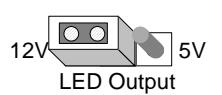
Wire the keypad, key-switch or other secure device to terminals 1 & 2 of this terminal strip.
Finally, connect 12 or 24 Volt AC or DC supply to terminals 1 & 2 of the 2-pin Power Connector. (The terminals are not polarity sensitive).
Step 4 Adjustments
In this application, you will use pots 1 – 5.
| Timer 1 | Strike Delay-on-release |
|---|---|
| Timer 2 | Operator Delay-on-activate |
| Timer 3 | Operator Delay-on-release |
| Timer 4 | Panic Relay (#4) ON time |
| Timer 5 | Panic Relay (#4) OFF time |
| Note: If pot 5 is turned to zero, | |
| relay will be on steady |
Apply power to door operator, EMF-2, and all connected equipment (ie – strike, lights, etc). Observe the red Power LED on the unit, which should light. If not, re-confirm proper voltage and/or
terminal strip connection.
Enter keypad, key-switch or other credential to activate EMF-2. Depending on dipswitch #8, the door will unlock and open or just unlock. If required press the exterior wall switch. Pot #1 adjusts the lock hold time. Pot #2 adjusts the door hold-open time (up to 30 seconds). (If the restroom is occupied and the Lock button has been pressed, then the door will not unlock or open).
After entering the restroom, push the Lock button. The EMF-2 will (de)energize the electric lock momentarily to let the occupant know the door is secure, and remove the exterior inputs from the circuit.
To exit the Restroom, two options are available:
- 1. To have the door unlock and open automatically, push the interior Wall switch. This will also reset the EMF-2 for the next person to use.
- 2. Manual Use. The door may also be used manually. To exit the restroom, turn the (lever) handle and pull (push) the door open. The magnet switch resets the unit into standby mode.
Emergency Panic Switch (optional)
Should an emergency occur, and assistance from the outside is required, the occupant can push a button or ribbon switch to signal the EMF-2. When activated, the EMF-2 will unlock the door (and optionally open the door). A maintaining type input is required to keep the door held open.
Further, Relay #4 is now activated, which can be used to signal for assistance, sound an alarm – whatever you choose. The installer can choose a continuous or pulsing output, depending on the settings of potentiometers # 4 & 5.
Emergency Time-out Feature
An added safety feature in the EMF-2 is the ability to automatically reset to standby mode after a fixed lock time of 15 minutes. The door will unlock, so that personnel may enter the restroom. This feature is engaged by turning dipswitch # 7 to ON position. If not desired, simply leave dipswitch 7 OFF .
Section 3D________________
Set-up Instructions 2-Door Restroom (Mode 4)
This application is a shared-use (normally unlocked) restroom between two suites (and therefore utilizing two doors), in facilities such as nursing homes & hospitals, etc. The relay provides control of both locks, operators, and all switches, to provide the utmost in flexibility, safety for the occupants, yet still be easy to install and program.
Either door is opened automatically by pressing the respective exterior wall switch. Once the door has closed, pressing either "Push to Lock" button inside then locks both doors – the strike is energized, and exterior switches are removed from the circuit. To exit the restroom, simply push either interior wall switch. The respective door unlocks, opens and resets the system. Should either door be opened manually, the magnetic contact switch will reset the system.
Unique to the EMF-2 is the emergency input, which allows a panic button to unlock, open (one or both) door(s), (optional), and send an emergency signal for assistance. The output can be maintained or pulsed. As an added safety feature, the EMF-2 can be set to automatically reset (and unlock) after 15 minutes time.
It is strongly encouraged to utilize the dry contact output (Relay #5) or the LED output to indicate " Occupied " on the exterior of both doors to let others know the restroom is in use.
Step 1
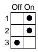
Select MODE 4 via the first 3 positions of the dipswitch as shown below:
See diagram 1 for location of dipswitch, connectors, & potentiometers.
IMPORTANT: Any changes Mode selector or Out2 settings must be made with power off!
Step 2 Dip switch Options
Leave switch #6 OFF to enable the panic button to unlock the door only, but not open it. Put dipswitch #6 ON when you want the panic button to unlock the door and also open it . Furthermore, if dipswitch #6 is set to ON , and dipswitch # 8 is set to OFF , then only
the last door used will open. Setting dipswitch #8 ON , will open both doors simultaneously.
Push dipswitch #7 ON , to enable the 15 minute Timeout (reset) feature. Leave in OFF position if you do not want an automatic reset.
Use of Relay 5 is optional, and set according to dipswitches #4 & 5. (See diagram 1 for location). A common use in this mode would be to have Relay 5 follow the lock relay and light an occupied sign. It could also be utilized for the second door lock, rather than connecting both door locks to Relay #1 output. By default, Relay #5 follows Relay #1.
Step 3 Connections
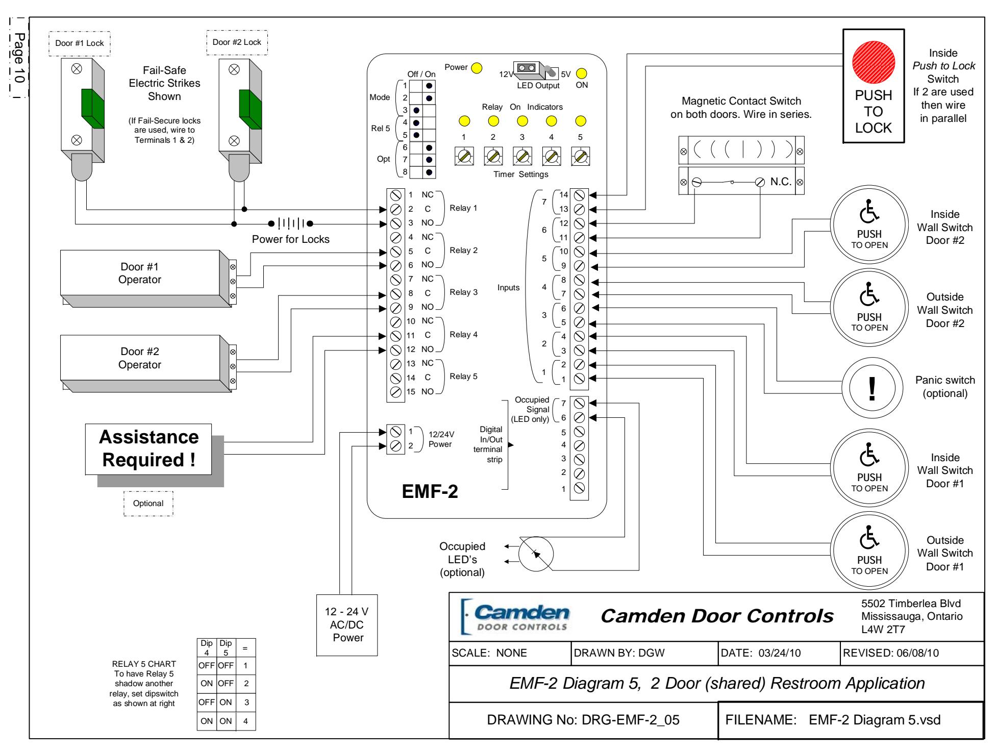
Refer to Diagram 5 (page 10) for the following connections.
Wire all input connections to the (removable) Input terminal strip (numbered 1 - 14). Firmly re-insert connector if removed.
Next, make your connections to the relay output strip (numbered 1 – 15). Both door locks may be connected to relay #1 or, wire one lock to Relay #1 and the other to Relay #5. Re-insert connector.
The 7-pin Digital I/O strip provides either 12V DC or 5V DC on Terminals 6 & 7 for lighting " Occupied " LED's. This output is present whenever the door is locked. Select output voltage using jumper as shown below:
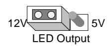
Finally, connect 12 or 24 Volt AC or DC supply to terminals 1 & 2 of the 2-pin Power Connector. (The terminals are not polarity sensitive).
Step 4 Adjustments
In this application, you will use pots 2 – 5. Pot #1 has no effect.
| Timer 2 | Operator Delay-on-activate |
|---|---|
| Timer 3 | Operator Delay-on-release |
| Timer 4 | Panic Relay (#4) ON time |
| Timer 5 | Panic Relay (#4) OFF time |
| Note: If pot 5 is turned to zero, | |
| relay will be on steady |
Apply power to door operators, EMF-2, and all connected equipment (ie – strikes, lights, etc). Observe the red Power LED on the unit, which should light. If not, re-confirm proper voltage and/or terminal strip connection.
Press the exterior wall switch at door #1. If the restroom is unoccupied the door will open automatically. Pot #2 adjusts the door hold-open time (up to 30 seconds). If the restroom is occupied and the Lock button has been pressed, then the door will not open. (An Occupied light would be lit.)
After entering the restroom, push the nearest Lock button. The EMF-2 will energize both electric locks and remove both exterior Push switches from the circuit.
To exit the Restroom, two options are available:
- 1. To have the door unlock and open automatically, push the respective interior Wall switch. This will also reset the EMF-2 for the next person to use.
- 2. Manual Use. The door may also be used manually. To exit the restroom, turn the (lever) handle and pull (push) the door open. The magnet switch resets the unit into standby mode. The Occupied lights / LED's will extinguish.
Repeat the above procedure door #2. It should function exactly as above.
Emergency Panic Switch (optional)
Should an emergency occur, and assistance from the outside is required, the occupant can push a button or ribbon switch to signal the EMF-2 (input #3). When activated, the EMF-2 will unlock the door (and optionally open the door). A maintaining type input is required to keep the door held open.
Based on the settings of Dipswitch #'s 6 & 8 either the doors will unlock only, or the last door used will open, or, both doors will unlock and open simultaneously.
Further, Relay #4 is now activated, which can be used to signal for assistance, sound an alarm – whatever you choose. The installer can choose a continuous or pulsing output, depending on the settings of potentiometers # 4 & 5.
Emergency Time-out Feature
An added safety feature in the EMF-2 is the ability to automatically reset to standby mode after a fixed lock time of 15 minutes. The door will unlock, so that personnel may enter the restroom. This feature is engaged by turning dipswitch # 7 to ON position. If not desired, simply leave dipswitch 7 OFF .
Section 3E________________
Set-up Instructions 2 / 3 door Airlock (Mode 5)
This function is designed to control up to 3 sets of sliding, or swinging doors. The relay will allow only 1 door to be open at a time.
It accomplishes this by a Door Sense input, such as a magnetic contact switch, located at each door. If the Door Sense determines that a door is open, then it will not allow a second door to open, but remembers the request to open and allows it once the first door has closed.
For 2-door airlocks, the installer can set up "Autocrossing" whereby after triggering one door, the second door will activate after the first door closes. (This is also known as bi-directional door sequencing).
Should a door become stuck open, a Trouble signal is output after 5 minutes. The EMF-2 also includes a "Lock-down" input that resets the system and/or disables all "Open" requests.
Step 1
Select MODE 5 via the first 3 positions of the dipswitch as shown below:
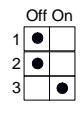
See diagram 1 for location of dipswitch, connectors, & potentiometers.
Step 2 Dip Switch Options
Use of Relay 5 is optional, and set according to dipswitches #4 & 5.
Push switch #6 ON for " Auto Mode " (door sequencing). In this Mode when input A is activated, first door A opens, then when closed again, door B opens in sequence. Conversely, when input B is activated, first door B opens, then when it is closed again, door A opens sequentially. A third door cannot be used in "Auto-Mode". Selecting this mode disables door C input and contact input.
Set dipswitch #7 ON for airlocks containing 2 doors only, or set to OFF for 3 doors. Dipswitch #8 has no effect in this mode.
IMPORTANT: Any changes to Dip switches, jumpers, and Mode selector settings must be made with power off!
Step 3 Connections
Refer to Diagram 6 (page 12) for the following connections.
Wire all input connections to the (removable) Input terminal strip (numbered 1 - 14). Firmly re-insert connector if removed.
NOTE: Concerning Magnetic contact switches. This system wants to see a Normally Closed connection when the door is closed. The contact will then open when the door opens. Any other configuration will cause the relay to malfunction. We suggest standard door contacts (ie - Camden Model # CX-MDC)
Next, make your connections to the relay output strip (numbered 1 – 15).
The 7-pin Digital I/O strip provides a trouble output on pins 6 & 7 after 5 minutes of door ajar.
Finally, connect 12 or 24 Volt AC or DC supply to terminals 1 & 2 of the 2-pin Power Connector. (The terminals are not polarity sensitive).
Step 4 Adjustments
In this application, you will use pots 1 – 3 & 5. Pot 4 is not used in this mode.
Timer 1 Door A delay-on-release Timer 2 Door B delay-on-release Timer 3 Door C delay-on-release
Timer 4 Not used
Timer 5 Timer for clearing " walk-aways "
Apply power to door operators, EMF-2, and all connected equipment (ie – strikes, lights, etc). Observe the red Power LED on the unit, which should light. If not, re-confirm proper voltage and/or terminal strip connection.
Activate an input device to one of the doors. Observe the respective output LED, which should light immediately. The door should unlock and/or open.
If a request to open comes in from another door while the first is still open, it will retain the call in memory until the Door Sense switch indicates the first has closed. If there is a succeeding request on the first door (or the door that is already opened) it will keep that door opened.
If automatic sequential operation between doors A and B is desired, then put dipswitch #6 into ON position. Otherwise, for normal operation, leave this dipswitch off.
Potentiometer #5 is useful if the application utilizes locks only, and not automatic door operators. Should a person approach a door and request the door to unlock, but then change his/her mind and "walkaway", pot #5 can be set to ignore that request after an adjustable time. Typically this time would be set at or close to minimum. For automatic door applications it could be set higher (10 – 15 seconds.)
Switch closure on Input #7 will cause all doors to lock immediately, regardless of pending "open" requests.
Once the desired operation is achieved, proceed to Section 4, System Inspection Instructions .
Section 3F________________
Set-up Instructions 2 - 5 door Airlock (Mode 6)
This function is designed to control up to 5 sets of sliding, or swinging doors. The relay will allow only 1 door to be open at a time.
It accomplishes this by a Door Sense input, such as a magnetic contact switch, located at each door. If the Door Sense determines that a door is open, then it will not allow a second door to open, but remembers the request to open and allows it once the first door has closed.
Should a door become stuck open, a Trouble signal is output after 5 minutes, and may be reset with Input #7.
Step 1
Select MODE 6 via the first 3 positions of the dipswitch as shown below:
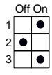
See diagram 1 for location of dipswitch, connectors, & potentiometers.
Step 2 Dip Switch Options
There are no dip switch options with this mode.
Since all door contacts are wired in series and connected to Input #6, the unit does not care if less than 5 doors are used.
IMPORTANT: Any changes Mode selector or Out2 settings must be made with power off!
Step 3 Connections
Refer to Diagram 7 (page 14) for the following connections.
Wire all input connections to the (removable) Input terminal strip (numbered 1 - 14). Firmly re-insert connector if removed.
NOTE: Concerning Magnetic contact switches. This system wants to see a Normally Closed connection when the door is closed. The contact will then open when the door opens. Any other configuration will cause the relay to malfunction. We suggest standard door contacts (ie - Camden Model # CX-MDC). Wire all contacts in series as shown in the diagram.
Next, make your connections to the relay output strip (numbered 1 – 15).
The 7-pin Digital I/O strip provides a trouble output on pins 6 & 7 after 5 minutes of door ajar.
Finally, connect 12 or 24 Volt AC or DC supply to terminals 1 & 2 of the 2-pin Power Connector. (The terminals are not polarity sensitive).
Step 4 Adjustments
In this application, you will use pots 1 & 5. Pots 2 - 4 are not used in this mode.
Timer 1 All Doors delay-on-release Timer 2 Not used
Timer 3 Not used Timer 4 Not used
Timer 5 Timer for clearing " walk-aways "
Apply power to door operators, EMF-2, and all connected equipment (ie – strikes, lights, etc). Observe the red Power LED on the unit, which should light. If not, re-confirm proper voltage and/or terminal strip connection.
Activate an input device to one of the doors. Observe the respective output LED, which should light immediately. The door should unlock and/or open.
If a request to open comes in from another door while the first is still open, it will retain the call in memory until the Door Sense switch indicates the first has closed. If there is a succeeding request on the first door (or the door that is already opened) it will keep that door opened.
Potentiometer #5 is useful if the application utilizes locks only, and not automatic door operators. Should a person approach a door and request the door to unlock, but then change his/her mind and "walkaway", pot #5 can be set to ignore that request after an adjustable time. Typically this time would be set at or close to minimum. For automatic door applications it could be set higher (10 – 15 seconds.)
Once the desired operation is achieved, proceed to Section 4, System Inspection Instructions .
Section 3G________________
Set-up Instructions 2 door Mantrap (Mode 7)
This function is designed to control a 2-door mantrap with or without automatic door operators. The relay will allow only 1 door to be open at a time.
It accomplishes this by a Door Sense input, such as a magnetic contact switch, located at each door. If the Door Sense determines that a door is open, then it will not allow a second door to open, but remembers the request to open and allows it once the first door has closed. (The memory feature may be disabled)
An input is available for a contact mat on the floor to ensure that only one person is within the mantrap at any time.
Should a door become stuck open, a Trouble signal is output after 5 minutes,
Finally, a "Lock-down" input is available which immediately locks all doors and disables further egress/ingress.
Step 1
Select MODE 7 via the first 3 positions of the dipswitch as shown below:
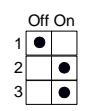
See diagram 1 for location of dipswitch, connectors, & potentiometers.
Step 2 Dip Switch Options
Use of Relay 5 is optional, and set according to dipswitches #4 & 5.
Push switch #6 ON to disable the memory feature. If left OFF , then the EMF-2 will remember a request to open and open that door when the other door has reclosed and locked.
Dipswitches #7 & 8 are not used in this mode.
IMPORTANT: Any changes to Dip switches, jumpers, and Mode selector settings must be made with power off!
Step 3 Connections
Refer to Diagram 8 (page 16) for the following connections.
Wire all input connections to the (removable) Input terminal strip (numbered 1 - 14). Firmly re-insert connector if removed.
NOTE: Concerning Magnetic contact switches. This system wants to see a Normally Closed connection when the door is closed. The contact will then open when the door opens. Any other configuration will cause the relay to malfunction. We suggest standard door contacts (ie - Camden Model # CX-MDC).
Next, make your connections to the relay output strip (numbered 1 – 15).
The 7-pin Digital I/O strip provides a trouble output on pins 6 & 7 after 5 minutes of door ajar. If utilizing an electric floor mat, wire to pins 1 & 2. (This input should be normally open).
Finally, connect 12 or 24 Volt AC or DC supply to terminals 1 & 2 of the 2-pin Power Connector. (The terminals are not polarity sensitive).
Step 4 Adjustments
In this application, you will use pots 1 - 3 & 5. Pot 4 is not used in this mode.
Timer 1 Door lock delay-on-release Timer 2 Operator delay-on-activate Timer 3 Operator delay-on-release Timer 4 Not used
Timer 5 Timer for clearing " walk-aways "
Apply power to door operators, EMF-2, and all connected equipment (ie – strikes, lights, etc). Observe the red Power LED on the unit, which should light. If not, re-confirm proper voltage and/or terminal strip connection.
Activate an input device to one of the doors. Observe the respective output LED, which should light immediately. The door should unlock and/or open.
If a request to open comes in from another door while the first is still open, it will retain the call in memory until the Door Sense switch indicates the first has
closed. If there is a succeeding request on the first door (or the door that is already opened) it will keep that door opened. This memory feature can be disabled by setting dipswitch #6 ON
Potentiometer #5 is useful if the man-trap utilizes locks only, and not automatic door operators. Should a person approach a door and request the door to unlock, but then change his/her mind and "walkaway", pot #5 can be set to ignore that request after an adjustable time. Typically this time would be set at or close to minimum. For automatic door applications it could be set higher (5 – 10 seconds.)
Once the desired operation is achieved, proceed to Section 4, System Inspection Instructions .
Section 4 _________________
System Inspection Instructions
After the Installation and operational check of the system:
- 1. Place warning label on the door (as per ANSI A156.10 or A156.19 guidelines). This will advise the person entering the swing side zone that the door will move.
- 2. Instruct the owner on door system operation and how to test it. This should be checked on a daily basis.
- 3. Instruct the owner on what to do if the door or any of its components become damaged.
- 4. Strongly recommend to the owner that the complete entry be inspected twice a year as part of the service agreement.
Section 5_________________
Technical Data
Models EMF-2 / EMF-2m / EMF-2ABM
Size EMF-2 7" x 3" x 7/8"
EMF-2m & EMF-1ABM
12" x 7.5" x 3.75"
Mounting EMF-2 Double sided foam tape
or two #6 screws
EMF-2m & EMF-2ABM
4 x Metal screws & anchors (provided)
Enclosure EMF-2 - Formed Plastic housing
EMF-2m & EMF-2ABM
- Beige Metal Cabinet
Firmware Version A1-001
Operating voltage 12 / 24 Volts, AC / DC
Current Draw 150 mA nominal
500 mA maximum
Response time 0.3 seconds
Mode Selector Via 3 dip-switches
Inputs 7 "dry" contacts,
1 Digital input
Outputs 5 SPDT relays
1 Digital output
Relay contact rating 3 amps @ 20 VDC
Time Delays 5 pots, adjustable from
1 to 30 seconds (depending
on mode selected)
Electrical Life 100,000 operations @ rated,
or 500,000 operations @ ½
rated capacity
In addition to above, Model EMF-2 ABM includes a lockable metal cabinet to house the relay. The cabinet is equipped with two lighted push-switches – on to turn the relay power on or off, and the other to control the DAY / NITE function.
Section 6_________________
Warranty
Camden Door Controls guarantees the EMF-2 (or EMF-2m / EMF-2ABM) to be free from manufacturing defects for 3 years from date of sale. If during the first 3 years the CX-EMF-2 / EMF-2ABM) fails to perform correctly, it may be returned to our factory where it will be repaired or replaced (at our discretion) without charge. Except as stated herein, Camden extends no warranties expressed or implied regarding function, performance or service.
Questions? Call us toll-free at 1-877-226-3369
Filename: CX-EMF-2 Instructions.doc Revision: 6/28/2012 4:02 PM