Camden CV-110SPK Standalone Keypad Prox Access Control Installation Instructions
Open the original PDF document
View PDF


CV-110SPK
Standalone Keypad/Prox Access Control Installation Instructions
1. Packing List
| Qty | Name | Remarks |
|---|---|---|
| 1 | Keypad | |
| 1 | User manual | |
| 1 | Screwdriver | 0.8" x 2.4" (20 mm×60 mm) |
| 2 | Wall plugs | 0.24" x 1.2" (6 mm×30 mm) |
| 2 | Self-tapping screws | 0.16" x 1.1" (4 mm×28 mm) |
| 1 | Torx screw | 0.12" x 0.24" (3 mm×6 mm) |
2. Description
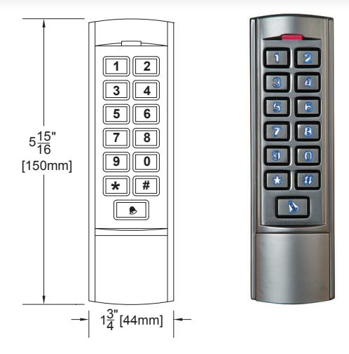
The CV-110SPK is a single door multifunction standalone keypad with a wiegand output for interfacing to an access control system or remote card reader. It is suitable for mounting either indoor or outdoor in harsh environments. It is housed in a strong, sturdy and vandal proof Zinc Alloy electroplated case. The electronics are fully potted so the unit is waterproof and conforms to IP68. This unit supports up to 2000 users in either a Card, 4 digit PIN, or a Card + PIN option. The built-in prox card reader supports 125KHZ EM cards. The unit has many extra features including lock output current short circuit protection, wiegand output, and a backlit keypad. These features make the unit an ideal choice for commercial and industrial applications such as factories, warehouses, laboratories, banks and prisons.
3. Features
- 2000 users, supports Card, PIN, Card + PIN
- · Backlit keys
- · Zinc Alloy Electroplated anti-vandal case
- · Waterproof, conforms to IP68
- · Easy to install and program
- · Wiegand 26 output for connection to a controller-
- · Full programming from the keypad
- Can be used as a stand-alone keypad
- · Wiegand 26 input for connection to external reader
- Adjustable Door Output time, Alarm time, Door Open time
- Very low power consumption (30mA)
- Fast operating speed, <20ms with 2000 users
- Lock output current short circuit protection
- Built in light dependent resistor (LDR) for anti-tamper
- Built in buzzer
- · Red, Yellow and Green LEDS status indicators
4. Quick Reference Programming Guide
| To enter programming mode |
*
Master Code # |
|
|---|---|---|
| To exit from the programming mode |
999999 is the default factory master code
* |
|
| Note: You must be in programming mode to program the following feature. | ||
| To change the master code |
0
New Code # New Code # |
|
| The master code can be 6 to 8 digits | ||
|
1
User ID Number # PIN # |
||
| To add a PIN user |
The ID number is any number between 1 & 2000. The
PIN is any four digits between 0000 & 9999 with the exception of 1234 which is reserved. Users can be added continuously without exiting programming mode. |
|
|
1
Read Card # |
||
| To add a card user |
Cards can be added continuously without exiting
programming mode |
|
|
2
User ID Number # for a PIN user or |
||
| To delete a PIN or a card user |
2
Read Card # for a card user |
|
|
Users can be deleted continuously without exiting
programming mode. |
||
| To unlock the door for a PIN user | Enter the PIN then press # | |
| To unlock the door for a card user | Present the card | |
5. Specifications
| Operating Voltage | 12V DC ±10% |
|---|---|
| User Capacity | 2,000 |
| Card Reading Distance | 1.25" to 2.4" (3 cm to 6 cm) |
| Active Current | < 60mA |
| Idle Current | 25±5 mA |
| Lock Output Load | Max 3A |
| Alarm Output Load | Max 20mA |
| Operating Temperature | -49°F to 140°F (-45°C to 60°C) |
| Operating Humidity | 10% - 90% RH |
| Waterproof | Conforms to IP 68 |
| Adjustable Door Relay time | 0 - 99 seconds |
| Adjustable Alarm Time | 0 - 3 minutes |
|
Wiegand 26 bit
Wiegand Interface |
|
|
Electric Lock, Exit Button, External Alarm, External Reader
Wiring Connections |
|
|
5 15/16" H x 1 3/4" W x 1" D (150 mm x 44 mm x 25 mm)
Dimensions |
|
6. Installation
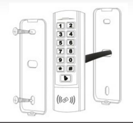
- Remove the back cover from the keypad using the supplied special screw driver
- Drill 2 holes on the wall for the Self tapping screws and 1 hole for the cable
- Put the supplied wall plugs into the two holes
- Attach the back cover firmly to the wall with the 2 Self tapping screws
- Thread the cable through the cable hole
- Attach the keypad to the back cover

| Color | Function | Description | |
|---|---|---|---|
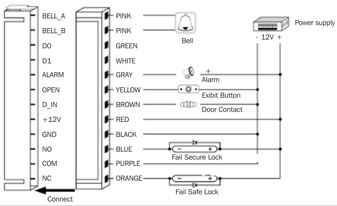
| Pink | BELL_A | Doorbell | |
| Pale Blue | BELL_B | Doorbell | |
| Green | D0 | Wiegand output D0 | |
| White | D1 | Wiegand output D1 | |
| Grey | ALARM | Alarm negative (alarm positive connected 12 V+) | |
| Yellow | OPEN | Exit button (the other end connected GND) | |
| Brown | D_IN | Door Contact switch (the other end connected GND) | |
| Red | 12V+ | 12V + DC Regulated Power Input | |
| Black | GND | 12V - DC Regulated Power Input | |
| Blue | NO | Relay Normally Open | |
| Purple | COM | Relay Common | |
| Orange | NC | Relay Normally Closed | |
Common power supply diagram:
8. To Reset to Factory Default
- a. Disconnect power from the unit
- b. Press and hold # key while powering the unit back up
- c. On hearing two "Beeps" release # key, system is now back factory settings
Note: Only the installer data is restored, user data will not be affected.
9. Anti-Tamper Alarm
The unit uses a LDR (light dependent resistor) as an anti-tamper alarm. If the keypad is removed from the cover, the tamper alarm will operate.
10. Sound and Light indication
| Operation Status | Red Light | Green Light | Yellow Light | Buzzer |
|---|---|---|---|---|
| Power on | - | Bright | - | Beep |
| Stand by | Bright | - | - | - |
| Press keypad | - | - | - | Beep |
| Operation successful | - | Bright | - | Beep |
| Operation failed | - | - | - | Beep/Beep/Beep |
| Enter into programming mode | Bright | - | - | - |
| In the programming mode | - | - | Bright | Beep |
| Exit from the programming mode | Bright | - | - | Beep |
| Open the door | - | Bright | - | Beep |
| Alarm | Bright | - | - | Alarm |
11. Detailed Programming Guide
11.1 User Settings
| To enter the programming mode |
*
Master code # |
||
|---|---|---|---|
| 999999 is the default factory master code | |||
| To exit from the programming mode | * | ||
| Note: You must be in programming mode to perform any of the following functions | |||
| To change the master code |
0
New code # New code # |
||
| The master code can be 6 to 8 digits long | |||
|
Setting the working mode:
Set valid card only users Set valid card and PIN users Set valid card or PIN users |
3
0 # Entry is by card only 3 1 # Entry is by card and PIN together 3 2 # Entry either by card or PIN (default) |
||
| To add a Pin user |
1
User ID number # PIN # |
|
|---|---|---|
|
The ID number is any number between 1 & 2000.
The PIN is any four digits between 0000 & 9999 with the exception of 1234 which is reserved. Users can be added continuously without exiting programming mode as follows: 1 User ID no 1 # PIN # User ID no 2 # PIN # |
||
| To delete a PIN user | ||
|
2 User ID number # Users can be deleted
continuously without exiting programming mode |
||
| To change the PIN of a PIN user |
*
ID number # Old PIN # New PIN # |
|
| (This step must be done out of programming mode) | New PIN # | |
| To add a card user (Method 1) |
1
Read card # |
|
| This is the fastest way to enter cards. The user ID | Cards can be added continuously without exiting | |
| number is automatically generated. | programming mode | |
|
To add a card user (Method 2). This is the alternative
way to enter cards using User ID Allocation. In this method a User ID is allocated to a card. Only one user ID can be allocated to a single card. |
1
ID number # Card # Users can be added continuously without exiting programming mode |
|
| To add card user (Method 3) | 1 Card number # | |
|
Card number is the last 5-8 digits printed on the
back of the card, user ID number is automatically generated |
Users can be added continuously without exiting
programming mode |
|
| To add a card user (Method 4) |
1
ID number # Card number # |
|
|
In this method a User ID is allocated to a card
number. Only one user ID can be allocated to the card number |
Users can be added continuously without exiting
programming mode |
|
|
To delete a card user by card. Note users can
be deleted continuously without exiting programming mode |
2
Read Card # |
|
|
To delete a card user by user ID. This option can
be used when a user has lost their card |
2
ID number # |
|
| To delete a card user by card number. |
2
Card number # |
|
| To add a card and PIN user in card and PIN mode ( 3 1 # ) | ||
|---|---|---|
| Add the card as if for a card user. See page 5 | ||
| To Add a card and Pin user | Press * to exit from the programming mode | |
|
(The PIN is any four digits between 0000 & 9999
with the exception of 1234 which is reserved.) |
Then allocate the card a PIN as follows: | |
|
*
Read card 1234 # PIN # PIN # |
||
|
To change a PIN in card and PIN mode (Method 1)
Note that this is done outside the programming mode so the user can do this themselves |
*
Read Card Old PIN # New PIN # New PIN # |
|
|
To change a PIN in card and PIN mode (Method 2)
Note that this is done outside the programming mode so the user can do this themselves |
*
ID number # Old PIN # New PIN # New PIN # |
|
| To delete a Card and PIN user just delete the card |
2
User ID # |
|
| To add a card user in card mode ( 3 0 # ) | ||
| To Add and Delete a card user |
The operating is the same as adding and deleting
cards in mode 3 2 # |
|
| To delete All users | ||
|
To delete ALL users. Note: This removes all user
2 0000 # codes. |
||
| To unlock the door | ||
| For a PIN user | Enter the PIN then press # | |
| For a card User | Read card | |
| For a card and PIN user | Read card then enter PIN # | |
11.2 Door Settings
| Relay Output Dealy Time | |||
|---|---|---|---|
| To set door relay strike time | * Master code # 4 0~99 # * | ||
| 0-99 is to set the door relay time 0-99 seconds | |||
| Door Open Detection | |||
|
Door Propped Open Alarm. When used with an optional magnetic contact or built-in magnetic
contact of the lock, if the door is opened normally, but not closed after 1 minute, the inside buzzer will beep automatically to remind people to close the door and continue for 1 minute before switching off automatically. |
|||
|
Door Forced Open Alarm. When used with an optional magnetic contact or built-in magnetic contact of the lock, if
the door is opened by force, or if the door is opened after 20 seconds of the electro-mechanical lock not closing properly, the inside buzzer and alarm output will both operate. The Alarm Output time is adjustable between 0~3 minutes with the default being 1 minute. |
|||
| To disable door open detection. (Factory default) |
6
0 # |
||
| To enable door open detection |
6
1 # |
||
| Alarm output time | |||
|
To set the alarm output time (0~3 minutes) Factory
default is 1 minute |
5
0~3 # |
||
|
Keypad Lockout & Alarm Output options. If there are 10 invalid cards or 10 incorrect PIN numbers in a
10 minute period either the keypad will lockout for 10 minutes or the alarm will operate for 10 minutes, depending on the option selected below. |
|||
|
Normal status: No keypad lockout or alarm
(factory default) |
7
0 # (Factory default setting) |
||
| Keypad lockout enable |
7
1 # |
||
| Alarm and inside buzzer enable |
7
2 # |
||
| To remove the alarm | |||
| To reset the Door Forced Open Alarm | Read valid card or Master Code # | ||
| To reset the Door Propped Open Alarm |
Close the door or Read valid card or
Master Code # |
||
12. Interfacing to an Access Control System
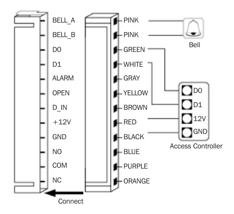
In this mode the keypad provides a 26 bit wiegand output. The wiegand data lines can be connected to any controller which supports the 26 bit wiegand protocol.
12.1 Keypad 8 bit Burst Mode
Every key pressed generates an 8 bit data stream that is transmitted over the wiegand bus.
| Key | Output | Key | Output |
|---|---|---|---|
| 0 | 11110000 | 6 | 10010110 |
| 1 | 11100001 | 7 | 10000111 |
| 2 | 11010010 | 8 | 01111000 |
| 3 | 11000011 | 9 | 01101001 |
| 4 | 10110100 | * | 01011010 |
| 5 | 10100101 | # | 01001011 |
Push Buttons Keypads Strikes Magnetic Locks Key Switches Relays & Timers Access Control
5502 Timberlea Blvd., Mississauga, ON Canada L4W 2T7
www.camdencontrols.com
File: Standalone Keypad/Prox Access Control
Installation Instructions.indd R3 Revision: 05/03/2018 Part No.: 40-82B190

Toll Free: 1.877.226.3369