Camden CM-330 Battery Operated Active Infra-red Hands-Free Switches Installation Instructions
Open the original PDF document
View PDF


CM-330 Battery Operated Active Infra-red "Hands-Free" Switches Installation Instructions
Section 1: General Description
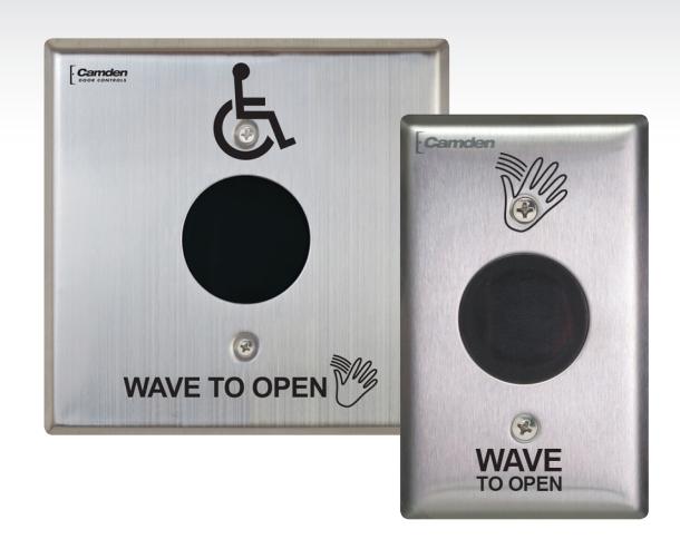
Sure-Wave™ Hands-Free Switch are active infra-red devices utilizing micro burst sensor technology, designed for use in ADA compliant automatic door control applications. The switches eliminate the spread of germs by avoiding physical contact and offer building occupants greater convenience when moving through the premises. Sure-Wave™ switches are available with either stainless steel or impact resistant polycarbonate faceplates, in narrow (jamb), single gang or double gang configurations. All models are ROHS compliant with lead-free construction.
Application
Sure-Wave™ battery powered hands-free switches are American Disability Act (ADA) compliant, and provide barrier free access and egress to buildings and washroom facilities. The rugged construction makes them ideal for use on low-energy automatic doors, drive-up windows, and interior and exterior doors in virtually any commercial (office, retail), institutional (school, hospital or clinic), or industrial (manufacturing) facility.
Three standard face plate widths are available:
CM-330: 2 ¾" x 4 ½" polycarbonate or stainless steel, fits on single gang electrical boxes.
CM-330/N: 1 ¾" x 4 ½" polycarbonate or stainless steel, fits 1 ¾" door frames or our CM-23D Jamb box.

CM-330/W: 4 ½" x 4 ½" polycarbonate or stainless steel, fits on single gang, double gang or 4 x 4 electrical boxes.
All faceplates may be ordered up with a plain face, with the waving hand symbol (/40), with the waving hand symbol and words: WAVE TO OPEN (/41) or with the waving hand icon, wheelchair and words: WAVE TO OPEN (/42).
Section 2: Installation
Mounting
Sure-Wave™ may be mounted in door jambs, single or double gang electrical boxes, and 4 x 4 boxes.
NOTE: The sealing gasket (included) is recommended for outdoor or wet locations. If using with Automatic doors install in accordance with ANSI A156.10 / A156.19. Select from one of the following three mounting subsections:
SINGLE GANG ELECTRICAL BOX: CM-330
- 1a If using an in-wall box ensure the box is plumb and square, and flush with the wall surface. (See Diagram 1)
- 1b If using a surface box, ensure it is secure & plumb.
- 2 Using the dip switch located on the end of the unit, set the operating mode. (See Section 4)
- 3 Attach the unit to the enclosure using the two #6-32 screws provided.
- 4 Attach the faceplate to the unit using the two black #6-32 x 3/8 machine screws or tamperproof screws.
Do not overtighten!!
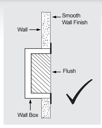
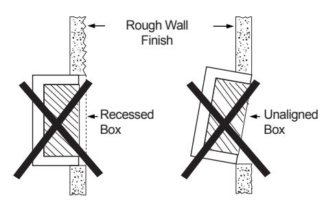
2- GANG (or 4x4) ELECTRICAL BOX: CM-330W Diagram 1 - Proper Box Installation
- 1a If using an in-wall box ensure the box is plumb and square, and flush with the wall surface. (See Diagram 1)
- 1b If using a surface box, ensure it is secure & plumb.
- 1c If using a 4 x 4 box, ensure the box is plumb and square, and flush with the wall surface, then attach the metal adaptor plate (included in the CM-330W package) to the box using appropriate fasteners.
- 2 Attach the unit to the enclosure using the two #6-32 screws provided.
- 3 Attach the faceplate to the unit using the two black #6-32 x 3/8 machine screws or tamperproof screws.
Do not overtighten!!
DOOR FRAME: CM-324N
1a - If mounting directly in a " wide aluminum jamb, make a cutout in the door frame at the intended location as per Diagram 3. (See Diagram 3 on page 3)
Drill and tap two mounting holes as shown.
- 1b If mounting the unit in our CM-23D deep jamb box, first mount the jamb box according to the instructions packaged with the enclosure. Using the CM-23D as a guide, drill a wire access hole through the jamb to fish the wiring through.
- 2 Using the dip switch located on the end of the unit, set the operating mode. (See Section 4)
- 3 Attach the unit to the enclosure or jamb using the two #6-32 screws provided.
4 – Attach the faceplate to the unit using the two black #6-32 x 3/8 machine screws or tamperproof screws.
Do not overtighten!!
Pairing the CM-330
CM-330 battery operated wireless SureWave™ utilizes our Lazerpoint RF technology and is for use with Camden CM-RX91 or CM-RX92 Lazerpoint receivers.
To pair the CM-330 transmitter to a receiver, press the PB1 (or PB2) button on the Receiver using a small blunt object such as a small blade screwdriver or similar. Within 10 seconds, wave your hand in front of the CM-330 to activate it. The Green LED Array on the receiver will flash once to confirm enrollment. Repeat with any additional CM-330 wireless Sure-wave™ switches. Activating the paired CM-330 again will signal the receiver that you are finished programming and LED's 1 & 2 will flash, in an alternating sequence. Activating the CM-330 a third time will activate the receiver's relay and corresponding LED, and also the device connected to the relay contacts.
If you wait longer than the 10 second period, the receiver will time out of Pairing Mode and revert back to standby. The LED will then flash to indicate the number of transmitters learned into the receiver.
Wiring
CAUTION: Do not apply power to the unit until all wiring is complete, and dip-switches have been set.
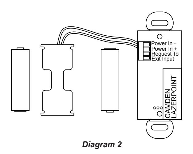
The CM-330 is powered from 2 AA batteries (supplied). The battery holder has been pre-installed. Insert the batteries into the battery holder. Please be careful that the polarity of the batteries is correct.
Section 3: Applications & Set-up Applications
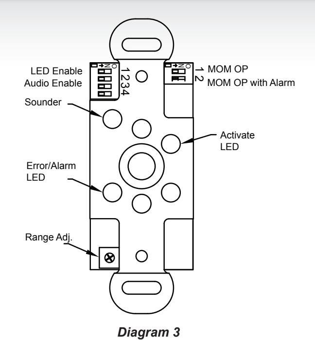
See Diagram 3 for the location of the Dip switches.
DIP Switch Settings DIP Switch 1
| CM-330 | Description | |
|---|---|---|
| 1 | LED Enable |
Green LED flashes while the output is
activated |
| 2 | Audio Enable |
Piezo buzzer sounds when the output is
activated |
| 3 | Not Used | |
| 4 | Not Used |
Switch 1 – LED On/LED Off
This switch disables the LED, should this feature be desired. Factory setting is OFF. This feature will decrease the battery life if set to ON.
Switch 2 – Audio Enable
Set this switch ON to enable an audible beep every time the switch is activated. Factory default is OFF. Enabling this feature will use additional power and decrease the life of the battery.
Dip Switch 2
| Function | SW1 | SW2 | Description |
|---|---|---|---|
| Momentary | OFF | OFF |
The output operates once and
only re-engages after the object is removed |
|
Momentary
with alarm |
ON | OFF |
The output operates once, and
only re-engages after the object is removed. If an object remains in the detectable area, an alarm will generate after approximately 30 seconds. |
Battery Strength Meter
To check the battery strength, place an object in front of the Surewave™ for approximately 5 seconds. The Surewave™ will beep up to 5 times indicating the battery charge level. 5 beeps being fully charged. 1-3 beeps indicates you should change the batteries.
Adjustments
Once the Dip switches have been set, and the unit is installed in the frame or enclosure, apply power to the unit and observe operation.
Set both potentiometers to minimum setting initially (fully counter-clockwise).
Adjust the range potentiometer by turning the pot in a clockwise manner, and passing your hand in front of the unit. Rotate the pot until the desired range is obtained. See Diagram 3 for locations.
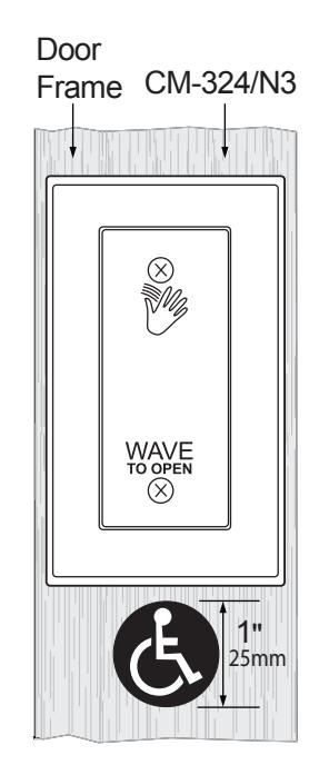
Diagram 4 Wheelchair Sticker Placement
Section 4: System Inspection Instructions
After the Installation and operational check of the system:
- 1. Place warning label on the door (as per ANSI A156.10 or A156.19 guidelines). This will advise the person entering the swing side zone that the door will move.
- 2. Instruct the owner on door system operation and how to test it. This should be checked on a daily basis.
- 3. Instruct the owner on what to do if the door or any of its components become damaged.
- 4. Strongly recommend to the owner that the complete entry be inspected twice a year as part of the service agreement.
Section 5: Technical Data
| No. of IR Sensors | (1) | |
| Batteries (Supplied) | (2) 'AA' Alkaline (Supplied) | |
| Estimated Battery Life | 2 Years (Based on 100 Operations/Day) | |
| Standard Operating Range |
1"- 12" (25.4mm - 304mm)
Factory Set to 6" (152mm) |
|
| Operating Mode | Momentary | |
| Inputs | 'Request to Exit' External (Door Contact) | |
| Wireless Output |
Built-in 915Mhz. Spread Spectrum
Wireless Transmitter |
|
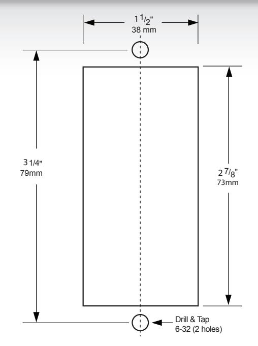
Diagram 5 Jamb Cutout Dimensions

Diagram 6 Adjustable Range Settings
Questions? Call us toll-free at 1-877-226-3369
Push Buttons
Key Pads
Strikes
Magnetic Locks
Key Switches
Relays & Timers
Access Control

5502 Timberlea Blvd., Mississauga, ON Canada L4W 2T7
www.camdencontrols.com Toll Free: 1.877.226.3369

File: CM-330 hands-free switches manual_R2.indd Revised: 03/05/2018 Part No: 40-82B194