CX-DESPK15 External Speaker
Open the original PDF document
View PDF

Door Activation Devices
CX-DESPK15 External 15 W Speaker Station
INSTALLATION INSTRUCTIONS
THIS PACKAGE INCLUDES:
(2) #6-3/8 screws
(1) Red / Green / Blue Aura PCB
(2) #6-32 1" SS FLT HD screws
(1) preamp PCB
1. GENERAL DESCRIPTION
CAMDEN DOOR CONTROLS CX-DESPK15 15-watt speaker station is designed for industrial and commercial applications, where both audio and visual indication is required. The station has an optional Aura™ feature to visually display three distinct colors for designated states: red, green, and yellow. The 15-watt speaker can provide audio messages where ambient noise may be present.
The faceplate is Stainless Steel with a Aura™ ring lens. This unit requires 12DC to operate.
Optional Aura™ PCB added:
Camden Aura™ PCB provides an added benefit of an illuminated enclosure. It offers field selectable red/green/blue illumination, activated directly by the switch or remotely by a relay* such as our CX-33 or EMF-2, a time-clock or access control system. User selectable features include a 3 Amp Form 'C' relay, and piezo for audible annunciation, as well as control over the idle and active LED colors. Another exclusive is the ability to plug in a TX-9 RF transmitter, thereby requiring only 2 conductors be run for power (no batteries required). The box is made of impact and flame-resistant black ABS. The illumination is provided by an array of super-bright and energy efficient LED's, which can be powered by 12 or 24 volts AC/DC. Note: only 12 VDC is provided for the amplified 15 Watt speaker station.
2. APPLICATION
Camden remote speaker station is ideal for applications that require a visual and audio capabilities such as a remote speaker station for delayed egress locks, door chimes or paging systems. It can be surface or flush mounted. Camden remote speaker station is designed to be wired to delayed egress maglocks, door chimes and other low voltage systems
3. SPECIFICATIONS
| Voltage | 8 - 24 VDC, 5 mA |
|---|---|
| Maximum Audio | 15 watt |
| Output impedance | 8 ohms |
Aura™ PCB
| Input Voltage | 12 or 24V AC/DC |
|---|---|
| Output Voltage | 3 Volts DC for TX-9 (only) |
| Current draw | 250 mA @ 12 VDC / 110 mA @ 24VDC |
| Contact Rating | 3A @ 30 VDC |
| Lumina Red | 14.8 lumens, 1600 mW |
| Lumina Green | 3.8 lumens, 330 mW |
| Sounder | 3200 ± 300 Hz @ 85 dB |
| Relay Contact | 1 x Form C |
4. FRONT AND SIDE - CM-DE502SO
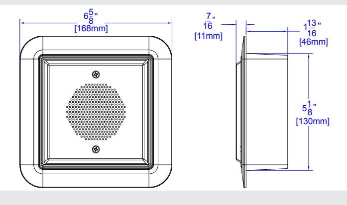
5. WIRING
| Device | Wire Color | Connection |
|---|---|---|
| Speaker | White | + audio |
| Black | - audio | |
| Amplifier | Normally Open | |
| White | Common |
| Device | Terminal | Connection |
|---|---|---|
| Aura | AC/DC | + 12-24V AC or DC |
| PWR | Common | |
| - PBTN | RED Rly C | |
| + PBTN | RED Rly NO |
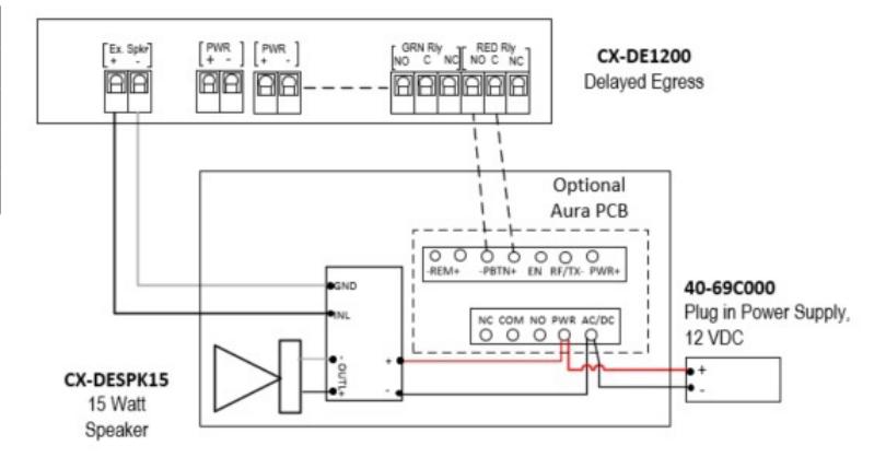
CX-DESPK15 EXTERNAL 15 W SPEAKER STATION
INSTALLATION INSTRUCTIONS
6. INSTALLATION
CX-DESPK15 uses a stainless-steel faceplate that can be easily mounted into Camden's surface or flush enclosures. Only xxxx" depth is required! NOTE: If you will be including the optional Aura™ signage, follow that product's installation instructions before installing Aura™
- 1. Determine the wire access location and drill hole of sufficient size, or use center knock-out plug. Drill the four required mounting holes. (11/64" min.) There are four indents provided on 3" centers for your convenience. (See Diagram 1)
- 2. Pull wiring through access hole, and mount the box to wall using 4 screws.
- 3. Remove circuit board from package and locate into the box. Pull the wire through the hole in centre of circuit board, and then secure with the two small self-tapping screws (provided).
- 4. Wire as per diagram (typical installation). Route the switch wiring through opaque diffuser panel, and install diffuser panel into box. It should fit snuggly.
- 5. Screw in two #6-32 head screws (provided with switch) into the threaded center inserts, then attach wires to switch and install switch over screws. Locate the screws and tighten (by hand only).
- 6. Connect power and test for proper operation.
CM-54i Wiring Diagram (Typical)
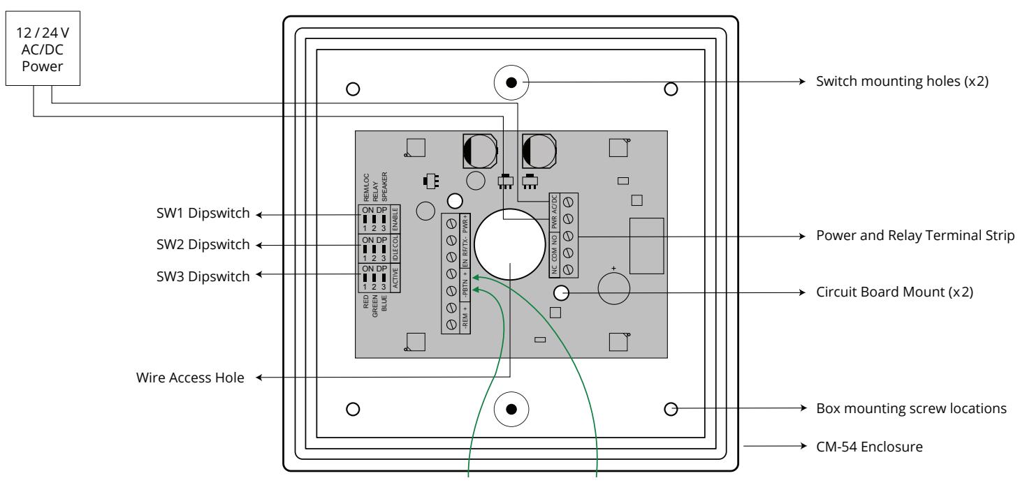
7. SET-UP:
Switch SW1 contains a bank of 3 dipswitches.
Dipswitch # 3 for Piezo. Turn off for 15-watt audio application.
Dipswitch # 2 toggles operation of the relay
Dipswitch # 1 allows you to choose whether the color will be changed locally via the push switch or remotely.
| Switch | Position | Description | |
|---|---|---|---|
| SW1 | 1 |
REMOTE / LOCAL On to enable
LED color change from idle to Active with press of the push button. |
|
| 2 | RELAY On to enable operation of the relay with activation of the push button. | ||
| 3 | Piezo Sounds On or OFF | ||
Color selection is made with Switches SW2 and SW3. SW2 determines the Active color and SW3 determines the Idle color.
Setting the IDLE Color (SW2)
| Switch | Position | Description | |
|---|---|---|---|
| SW2 | 1 | ON = Red LED when IDLE | |
| 2 | ON = Green LED when IDLE | ||
| 3 | ON = Blue LED when IDLE | ||
Setting the Active Color (SW3)
| Switch | Position | Description | |
|---|---|---|---|
| SW3 | 1 | ON = Red LED when Active | |
| 2 | ON = Green LED when Active | ||
| 3 | ON = Blue LED when Active | ||
NOTE: If all DIP switches are in the OFF position, there will be no color illuminated. This allows for no Idle color or no Active color.
8. PARTS INFORMATION
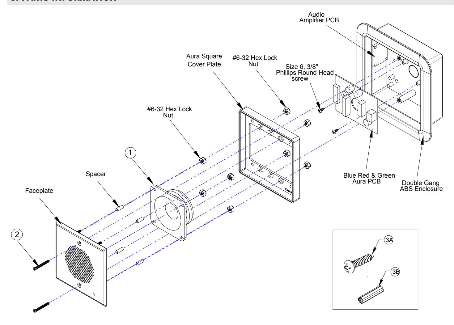
| MODEL NUMBERS | ||||
|---|---|---|---|---|
|
ITEM NUM
BER |
MODEL NUMBER | QTY | DESCRIPTION | |
| 1 | 60-64B001 | 1 | REMOTE 15-WATT SPEAKER | |
| 2 | 60-51C221E040 | 1 | 6-23 X 1/4'' FLAT HEAD PHILLIPS SCREW | |
| PARTS KIT | ||||
|
ITEM NUM
BER |
PART NUMBER | QTY | DESCRIPTION | |
| 3. | 60-34B018 | 1 |
(A) #10 X 1'' PAN HEAD PHILLIPS WOOD SCREW (4 Pcs)
(B) EXPANDET GREEN ANCHORS (4 Pcs) |
|