CX-DE1200 Manual
Open the original PDF document
View PDF

Electrified Locks, Relays and Timers
CX-DE1200 Delayed Egress Electro Magnetic Lock Special Locking Arrangement


INSTALLATION INSTRUCTIONS
THIS PACKAGE INCLUDES:
- 1- CX-DE1200 Electro Magnetic Lock Housing assemble with main controller PCB & Magnetic Plate
- 1- Mounting Template
- 4- Adhesive door signage
- 1- Installation Instructions & Wiring Diagrams
- 1- Armature Plate Assembled Housing & Proxy Trigger
- 1- Electro Magnetic Lock Screw Packaging
Building & Fire Life Safety Code Compliant:
IBC International Building Code
NFPA 101 Life Safety Code
NFPA 1 , UFC Uniform Fire Code
CBC California Building Code
BOCA National Building Code
Chicago Building Code
THIS PRODUCT MUST BE CONNECTED INTO A FIRE ALARM SYSTEM PER NFPA CODE OR OTHER REGULATIONS SO THAT, IN THE EVENT OF FIRE, THE TIME DELAY WILL BE BYPASSED. CONTACT YOUR LOCAL CODE AUTHORITY TO VERIFY COMPLIANCE WITH FIRE AND BUILDING CODES. THE DELAYED EGRESS DEVICE SHOULD BE ROUTINELY CHECKED FOR PROPER OPERATION AND COMPLIANCE WITH FIRE AND BUILDING CODES.
1. DESCRIPTION
Intended for use in an Indoor location - Out Swing.
When an unauthorized exit is trigger, the delays exit through the door for a period of 15 or 30 seconds. An LED bar segment display countdown by seconds and voice messages to inform the person planning to exit with the remaining times to unlock.
In the meantime, the person exiting must wait to allow time for security personnel or staff to respond. The door will eventually unlock after the 15 or 30 seconds delay time has passed, permitting the exit. During an emergency, a signal from the fire/life safety system will release the lock promptly.
PUSH UNTIL ALARM SOUNDS. DOOR CAN BE OPENED IN 15 SECONDS.
PUSH UNTIL ALARM SOUNDS. DOOR CAN BE OPENED IN 30 SECONDS.
KEEP PUSHING. THIS DOOR WILL OPEN IN 15 SECONDS. ALARM WILL SOUND.
KEEP PUSHING. THIS DOOR WILL OPEN IN 30 SECONDS. ALARM WILL SOUND.
2. SPECIFICATIONS
| Voltage |
12/24V DC +/- 10% (Auto Sensing)
Power Suplly must be UL 294 or UL 603 Listed with a Class 2, power limited output |
|---|---|
| Current Draw | 600mA / 350mA |
| Lock Output | 12/24 VDC, 1A |
|
Lock Status Relay
Rating Max. * |
30 VDC, 2A, 1 pF |
|
Alarm Output
Rating Max. * |
30 VDC, 2A, 1 pF |
| DPS Rating Max. * | 30 VDC, 0.1A, 1 pF |
| Bond Sensor Rating Max. * | 30 VDC, 2A, 1 pF |
| ATS Rating Max. * | 30 VAC / 42.4 VDC, 5A, 1 pF |
| Operating Temperature | 0~55°C (32~131°F) |
| Operating Humidity | 0~95% (non-condensing) |
|
Dimensions
(Lock) |
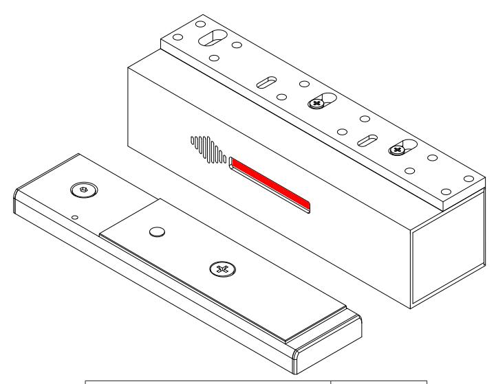
11" H x 3" W x 3" D
(280mm x 76mm x 74.5mm) |
|
Dimensions
(Armature Plate) |
11" H x 2-5/8" W x 1" D
(280mm x 68mm x 23.5mm) |
Note: * Separately-energized
3. DIMENSIONS
|
UL 294 Access Control
Performance Levels: |
Levels: | |||
|---|---|---|---|---|
| Access Control Line Security | Level I | |||
| Destructive Attack | Level I | |||
| Endurance | Level IV | |||
| Standby Power | Level I | |||
4. FEATURES
- Holding Force up to 1200 Lbs. (Not validated by UL)
- Field selectable exit delay time 15 or 30 seconds
- Nuisance Delay period either 1, 2 or 3 seconds
- 75dB Buzzing Tone with LED segment bar display time seconds & field selectable voice alerts
- Choice of sensor to be activated:
- Door Motion
- Door Exit Device with momentary normally open contact
- Push Bar with momentary normally open contact
- Auto Start Up:
- Occurs when power supply is restored and/or the fire panel is restored (When allowed by Building & Fire Life Safety Code)
- Manual Start Up:
- This is a California & UBC Building Code Compliant Feature. Only after power supply restoration and fire panel reset may the lock be Reset manual at the opening. This lock can be reset with the built-in reset key switch or an external key switch or a reset switch connected to the door
- Vandal resistant Proximity Trigger Sensor
- Auto Sensing Voltage Power Input 12/24 VDC
- Reverse power protection: If someone hooks power up backwards, the board simply does not turn on, protecting it from damage
- Optional Connection for Auxiliary Lock, CX-DE1201 (Double Leaf Door)
- Hall Effect Sensor Monitoring Output
- Tamper Switch Output
- Tailgating Prevention door will re-lock as soon as it closes
- Anti-Pass Back / Auto re-lock: If door doesn't open after the count down, the door will automatically re-lock.
5. INSTALLATION CONCEPT AND ACCESSORIES
Seven configuration versions are available to be compliant to regional jurisdictions.
| Models |
Delay Release Time
(Seconds) |
Nuisance Delay
(Seconds) |
Reset After Alarm | Lock Status on Power-Up | |||||
|---|---|---|---|---|---|---|---|---|---|
| Fixed | Selectable | Fixed | Selectable | Selectable | Fixed | Fixed | Selectable | ||
| CX-DE1200-N1 | 15 or 30 | 1 or 2 | Manual | Locked / Unlocked | |||||
| CX-DE1200-N2 | 15 | 0 or 1 | Manual | Locked / Unlocked | |||||
| CX-DE1200-N3 | 30 | 0 or 1 | Manual | Locked / Unlocked | |||||
| CX-DE1200-N4 | 15 | 0 or 1 | Manual | Unlocked | |||||
| CX-DE1200-B1 | 15 | 0 or 3 | Auto / Manual | Locked / Unlocked | |||||
| CX-DE1200-B2 | 30 | 0 or 3 | Auto / Manual | Locked / Unlocked | |||||
| CX-DE1200-B3 | 15 | 0 | Auto / Manual | Locked / Unlocked | |||||
| N# = NFPA Compliance | B# = BOCA Compliance | ||||||||
BOCA Compliance
Manual Reset: Is achieved by authorized personnel closing the door after an alarm and actuating the integral reset key switch or by momentarily closing a contact connected to the remote RESET terminal.
Automatic Reset: Reset will automatically be initiated once the door has been opened, then closed and remains closed for 30 consecutive seconds.
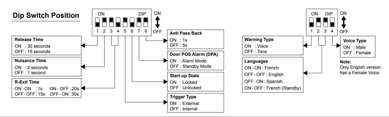
Dip Switch Settings
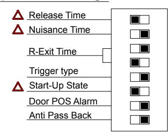
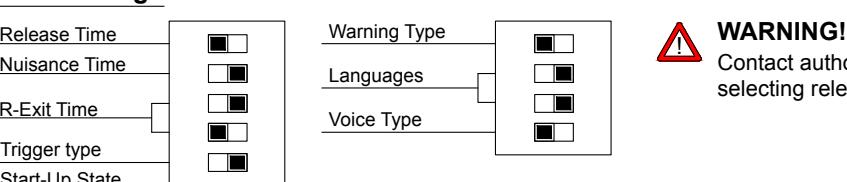

Contact authority having jurisdiction for approval prior to selecting release time, nuisance time and start-up settings.
6. ARMATURE MOUNTING INSTRUCTIONS
Step 1: Close the door, position the EM lock mounting location as close to the upper corner of the door with a minimum gap 1".
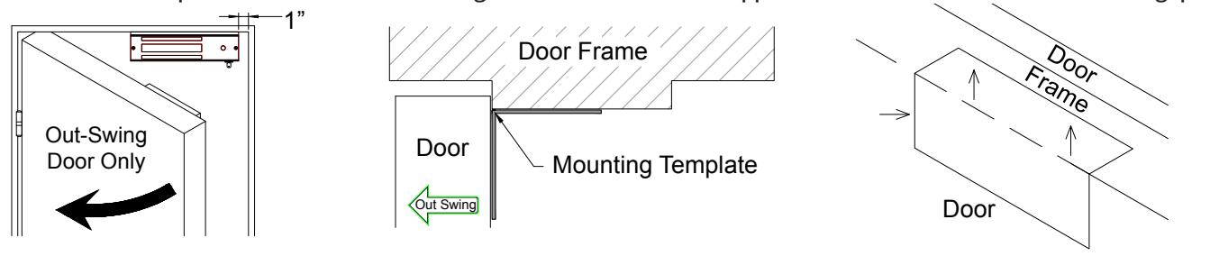
Step 2: Place the template against the door and frame and drill holes according to template indications.
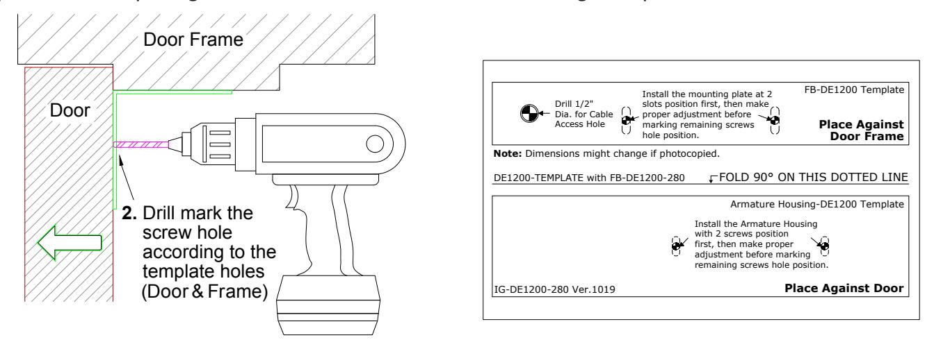
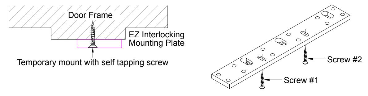
Step 3: Place the mounting plate against the door frame and screw in according to the template holes position.
Step 4: Place the armature housing against the door and screw in according to the template holes position
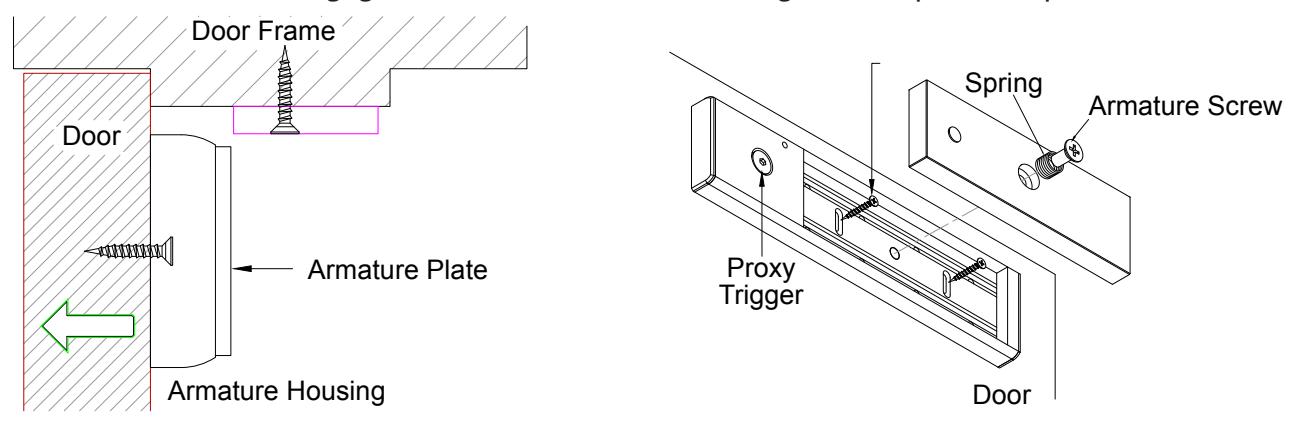
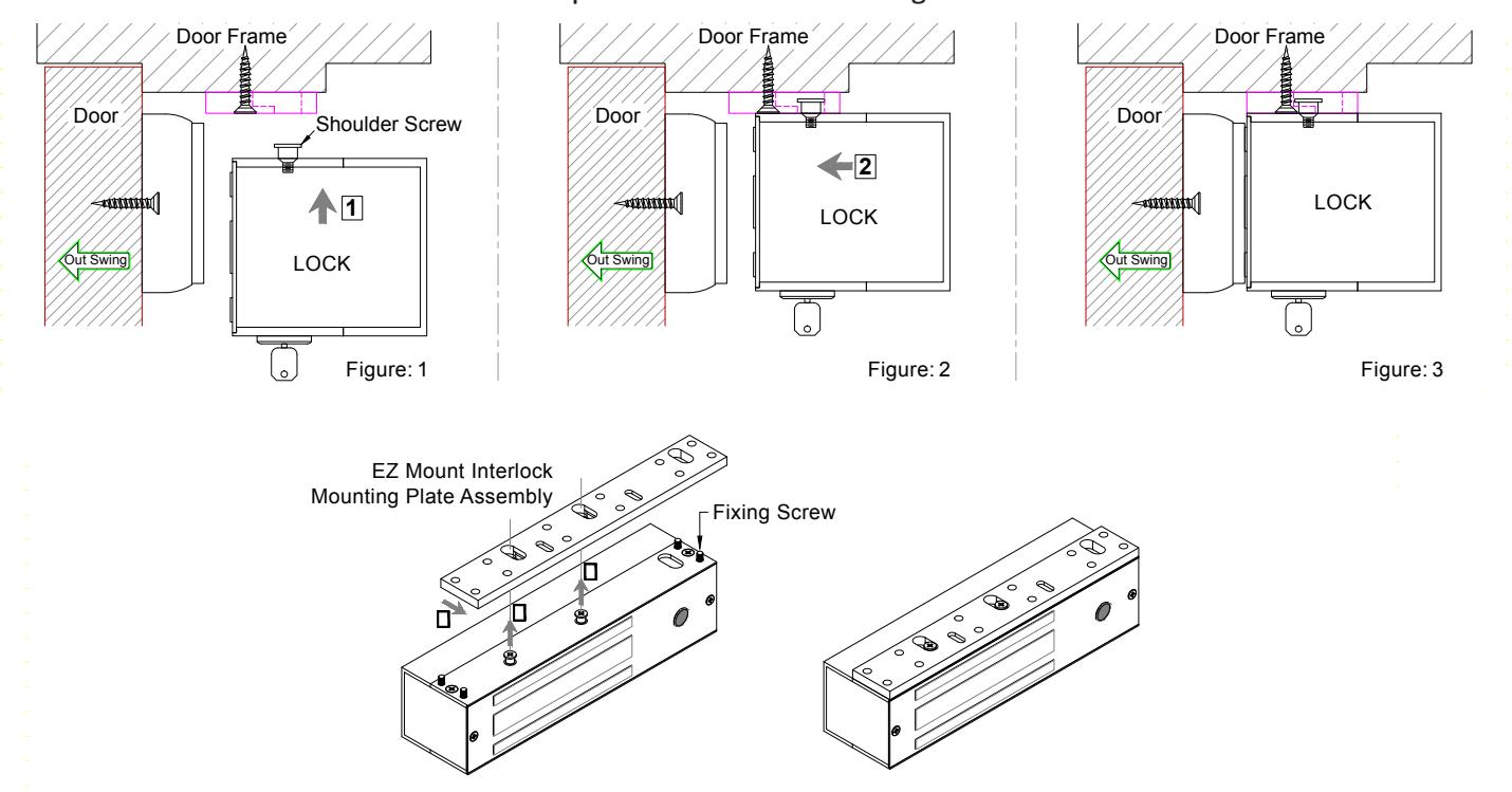
Step 5: Slot in the electromagnet lock unit through the shoulder screw into the EZ mounting plate as shown in Figure 1-2 below. CAUTION: The lock unit must be held in place until secured with fixing screws.
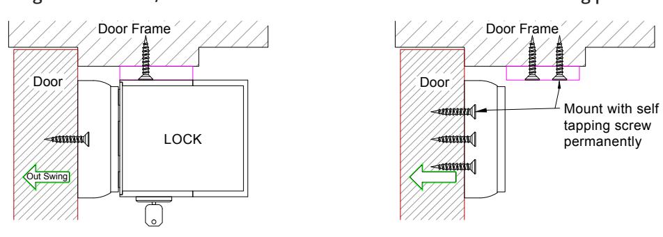
Step 6: Align the lock unit with the mounting plate. Fix the lock unit to the mounting plate with the allen key given through fixing the screw. Carefully screw into the mounting plate to avoid stripping the threads. Check and confirm the alignment and mating surface between the armature plate and lock unit.
NOTICE: Loosen screw #1 or #2 to re-align the mounting plate and position the lock unit mating surface to fully attach with the armature plate. Re-tighten screw #1, #2 and screw-in the balance screw holes of mounting plate and armature housing.
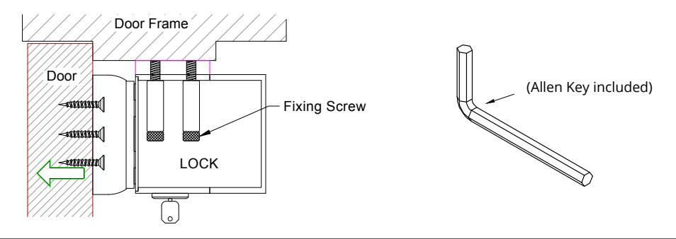
Step 7: Pull the wires through the door frame, mounting plate and into the electromagnetic lock unit casing. Fix the electromagnet lock unit to the mounting plate with the fixing screw. Make sure to fully tighten the fixing screw with the proper tool (eg. "T" Handle Allen Key).
INSTALLATION INSTRUCTIONS
Step 8
After the lock unit has been mounted to the door and frame as per the provided template, route the wires through the access hole and out to the controller board. Re-mount the lock front cover onto the lock. Make sure the proxy sensor is aligned with the hole on the cover. The sensor height is factory default which slightly projected out from the surface cover.
CAUTION: Do not attempt to adjust the proxy sensor height, as this will result in damage to the sensor and void the warranty.
Step 9
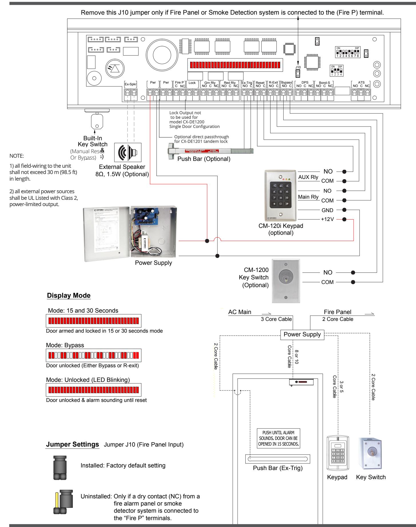
Make all wiring connections to the lock controller board. Special precaution on the polarity of the input power terminals. This lock has auto sensing voltage feature which automatically configures itself for 12 VDC or 24 VDC operation. Correct power supply voltage must be used for proper lock operation.
NOTE: The length of wiring to all field-wiring terminals shall not exceed 98.5 ft (30 m)
CAUTION: Input terminals for R-Exit, Reset & Ex-Trig must only be connected to a normally open momentary dry contact switch. Connection to a voltage or "wet" output may damage the lock and void the warranty.
Step 10
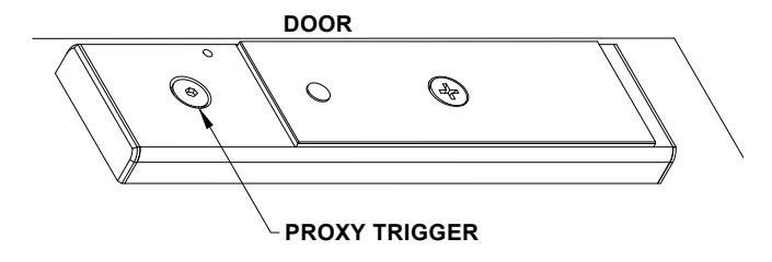
Slowly swing the door closed and visually check the position of the proxy trigger as it approaches the proxy sensor on the lock. The proxy trigger & sensor should align between one another either horizontally or vertically, if the installation was done perfectly using the provided mounting template. The LED at the back of the proxy sensor will light on when the proxy trigger is detected.
IMPORTANT NOTICE: Standard operation of the lock depends on the proxy sensor being able to detect the proxy trigger when the door is swing closed. A minor adjustment can be made to the proxy sensor height for fine tuning.
Step 11
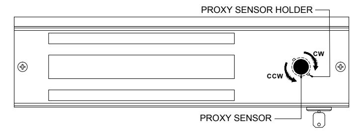
Fine Tuning Proxy Sensor Height:
- Turning proxy sensor holder clockwise (CW) will increase the height of the proxy sensor from the front cover surface; hence decreasing the gap between the sensor and proxy trigger.
- Turning proxy sensor holder counterclockwise (CCW) will decrease the height of the proxy sensor from the front cover surface; hence increasing the gap between the sensor and proxy trigger.
Step 12
Fine Tuning Door Movement Detection Sensitivity:
The proxy trigger is spring loaded and can be screwed in or out from the proxy trigger ABS housing using the provided Allen key M5. Hence, increase or decrease the gap between the sensor and proxy trigger.
IMPORTANT NOTICE: Standard installation of the proxy sensor and proxy trigger does not have to touch each other physically to operate correctly.
Release Time:
The Release time can be selectable either 15 or 30 seconds. The Nuisance time delay is included in the door Release cycle and the total time to unlock the door remain the same as per setting once sensor is triggered.
Nuisance Time:
The Nuisance time feature is a warning time delay that commences when pressure is applied to outward swinging doors. Releasing the door before the end of the nuisance time, will turn off the warning alarm buzzer and reset nuisance time to origin. Nuisance time is field selectable for 1, 2 or 3 seconds. Triggering the proxy sensor beyond the nuisance time will start the irreversible Release cycle time. The Nuisance time is included in the lock Release time cycle.
R-Exit Time:
The Request Exit (R-Exit) time is field selectable for 1, 15, 20, or 30 seconds. The R-Exit time is the duration for the lock that will remain Unlocked (Bypass), after a remote normally open contact switch is momentarily activated. When activated with an access control system, the R-Exit time cycle will start after the access control relay open time expires. The door will automatically re-lock if the door is opened, then closed during the R-Exit time cycle.
Trigger Type:
The trigger type is field selectable either EXTERNAL or INTERNAL. Selecting INTERNAL mode uses the built-in proxy sensor and EXTRIG terminal to trigger the Release Time cycle. Selecting External mode will disable the INTERNAL mode sensor; activation of the Release Time cycle is triggered by an external egress device equipped with a normally open contact switch.
Start-Up State:
The Start-Up selection, imply the state of lock during restoration of power up. It is field selectable either be LOCKED or UNLOCKED. In the LOCKED mode, the lock will be reset to secure mode. In the UNLOCKED mode, the lock will remain unlocked and the LED Bar display will indicate as per By-Pass mode. To reset the lock; a momentarily normally open contact to the RESET signal will re-lock the door. This feature selection is to comply with building code requirements in jurisdictions that require manual reset or re-lock upon loss and restoration of system power supply.
Warning Type:
The warning type is field selectable either TONE or VOICE. In secure status, the LED Bar displays a 15 segment or 30 segment LED light. Each segment represents. Upon activation of the irreversible Release Time cycle, the LED Bar segment display begins to turn off one by one. In VOICE mode, the countdown will be counted along with verbal exit guidance. When the LED bar display reaches zero, the lock will release. The verbal voice guidance changes to a continuous verbal instruction announcing, "Door Unlocked". In TONE ONLY mode, the countdown will be accompanied with a beeping tone only, and a continuous tone is heard once the Release time cycle ends.
Languages:
The voice message can be in 3 languages which are field selectable. The languages are English (Default), French and Spanish.
Voice Type
For English only, the voice type is field selectable for either a male or female voice.
Examples:
- 15 seconds Mode: "Door will unlock in 15 seconds; Door will unlock in 5 seconds; Door unlocked..." (Both messages repeat "Door unlocked" until the lock is reset).
- 30 seconds Mode: "Door will unlock in 30 seconds; Door will unlock in 20 seconds; Door will unlock in 10 seconds; Door will unlock in 5 seconds; Door unlocked..." (Both messages repeat "Door unlocked" until the lock is reset).
Door POS Alarm (DPA):
- DPA Active: The lock will enter alarm mode when the door is held open past the R-Exit time period triggering a buzzing tone or alarm voice and the DPA can be Reset by the built-in key switch or remote reset.
- DPA Inactive: The lock will enter stand-by mode which will remain unlocked if the door is held open past the R-Exit time set. No warning sound is emitted. The Lock can re-lock upon closure of the door.
Anti-Pass Back
If door doesn't open after the count down, the door will re-lock after a set time frame: 1 or 5 seconds.
7. CONFIGURATION
| Configuration Release |
Nuisance
Delay |
Request to Exit Period |
Trigger
Type |
Power-Up
State |
Door Prop
Open |
p Anti-Pass
Back |
Reset After
ALARM |
|||||||||||
|---|---|---|---|---|---|---|---|---|---|---|---|---|---|---|---|---|---|---|
| Options | Sw | itch 1 | Switch 2 Switch 3 4 Swi | Switcl | n 5 | Switch | n 6 | Switc | Switch 8 | |||||||||
| N1 | 15 | OFF | 1 | OFF | 1 Sec | ON | ON | Internal | OFF | Unlocked | OFF |
Stand-
by |
OFF | 5 | OFF | Fixed Manual | ||
| 30 | ON | 2 | ON | 15 Sec | OFF | OFF | External | ON | Locked | ON | Alarm | ON | 1 | ON | ||||
| ۸۱۱ م | ntions | selectab | do | 20 Sec | ON | OFF | ||||||||||||
| All C | puons | Selectab | ле | 30 Sec | OFF | ON | ||||||||||||
| N2 | 15 |
Not
Used |
0 | OFF | 1 Sec | ON | ON | Internal | OFF | Unlocked | OFF |
Stand-
by |
OFF | 5 | OFF | Fixed Ma | anual | |
| 15 | Oseu | 1 | ON | 15 Sec | OFF | OFF | External | ON | Locked | ON | Alarm | ON | 1 | ON | ||||
| N | EDA Co | mpliant | 20 Sec | ON | OFF | |||||||||||||
| IN | - CO | ппрпапс | 30 Sec | OFF | ON | |||||||||||||
| N3 | 30 |
Not
Used |
0 | OFF | 1 Sec | ON | ON | Internal | OFF | Unlocked | OFF |
Stand-
by |
OFF | 5 | OFF | OFF Fixed Manual | ||
| 30 | USEU | 1 | ON | 15 Sec | OFF | OFF | External | ON | Locked | ON | Alarm | ON | 1 | ON | ||||
| N | EDA Co | mpliant | 20 Sec | ON | OFF | |||||||||||||
| IN | IFFA CO | inpliant | 30 Sec | OFF | ON | |||||||||||||
| N4 | 15 |
Not
Used |
0 | OFF | 1 Sec | ON | ON | Internal | OFF | Unlocked |
Not
Used |
Stand-
by |
OFF | 5 | OFF | Fixed Manual | ||
| 15 | USEU | 1 | ON | 15 Sec | OFF | OFF | External | ON | Unlocked | USEU | Alarm | ON | 1 | ON | ||||
| NFPA/OSHPD Compliant. Power Up | Up | 20 Sec | ON | OFF | ||||||||||||||
| unlocked a | unlocked and manual reset is fixed. | ed. | 30 Sec | OFF | ON | |||||||||||||
| 1 | Not | Used | Switch | n 8 | ||||||||||||||
| B1 | 15 |
Not
Used |
0 | OFF | 1 Sec | ON | ON | Internal | OFF | Unlocked | OFF |
Stand-
by |
OFF | = | Manual | OFI | ||
| 15 | Oseu | 3 | ON | 15 Sec | OFF | OFF | External | ON | Locked | ON | Alarm | ON | Auto | ٥N | ||||
| BOCA Compli | reset | 20 Sec | ON | OFF | ||||||||||||||
|
nuous sed
r closure |
30 Sec | OFF | ON | |||||||||||||||
| B2 | 30 | Not | 0 | OFF | 1 Sec | ON | ON | Internal | OFF | Unlocked | OFF |
Stand-
by |
OFF | Manual | Off | |||
| 30 | Used | 3 | ON | 15 Sec | OFF | OFF | External | ON | Locked | ON | Alarm | ON | Auto | ON | ||||
|
BOCA Compliant. Automatic alarm reset
after 30 continuous seconds from door closure. |
reset | 20 Sec | ON | OFF | ||||||||||||||
| 30 Sec | OFF | ON | ||||||||||||||||
| В3 | 15 | INOL | Not | 1 Sec | ON | ON | Internal | OFF | Unlocked | OFF |
Stand-
by |
OFF | Manual | OF | ||||
| 15 | Used | 0 | Used | 15 Sec | OFF | OFF | External | ON | Locked | ON | Alarm | ON | Auto | ON | ||||
| BOCA/Ch | 20 Sec | ON | OFF | |||||||||||||||
| uisance. Automatic alarm reset after 30 continuous seconds from door closure. | 30 Sec | OFF | ON | |||||||||||||||
8. PARTS REPLACEMENT
|
ITEM
NUMBER |
QTY | DESCRIPTION |
|---|---|---|
| 1 | 1 | MOUNTING PLATE |
| 2 | 1 | ELECTRO MAGNETIC LOCK SCREW PACKAGING |
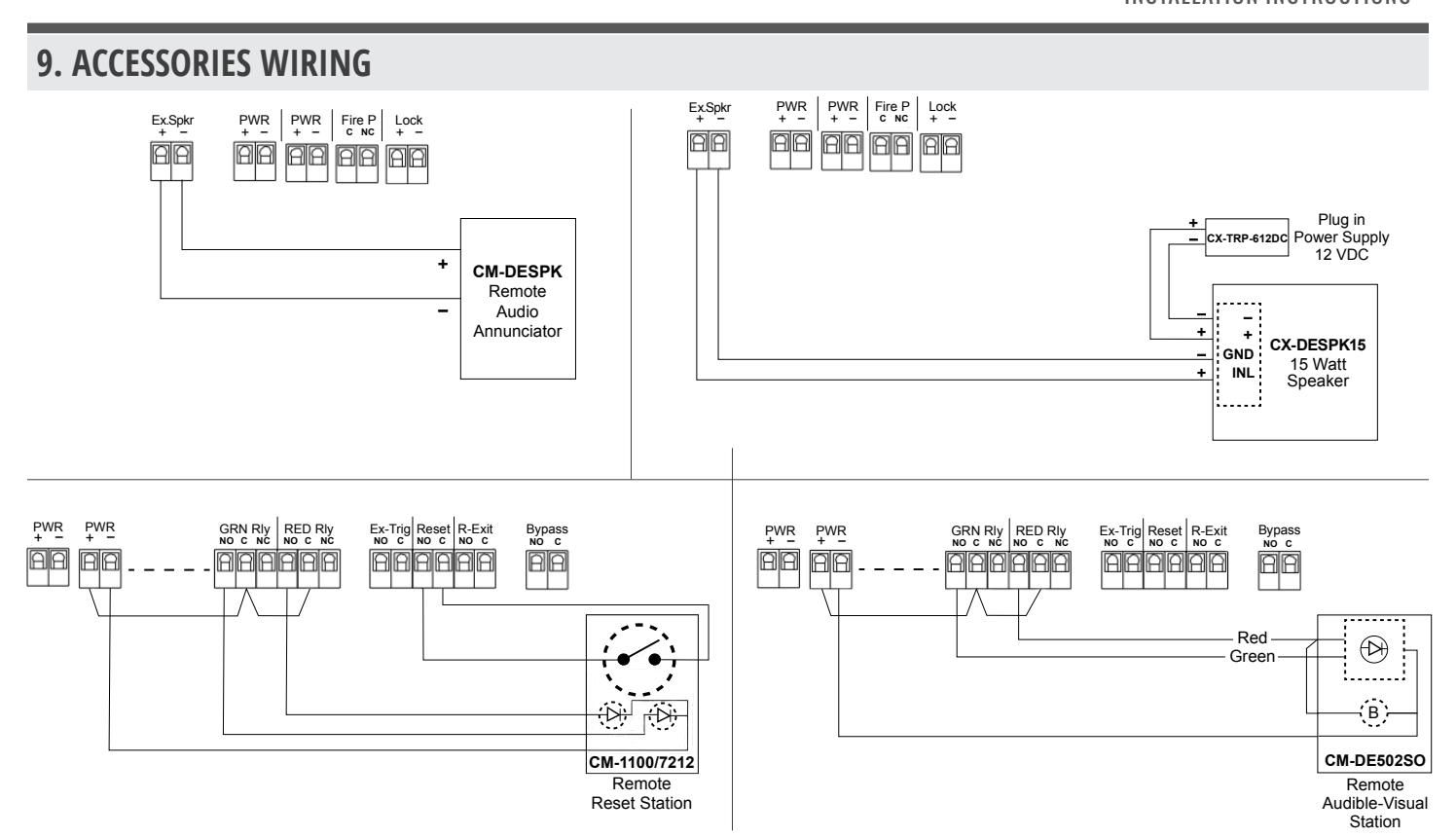
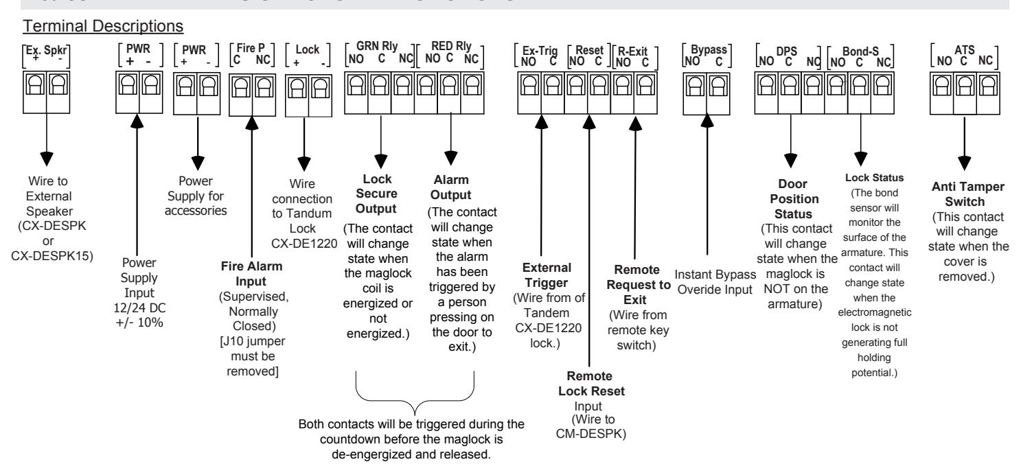
10. COMPLETE WIRING OPTIONS AND FUNCTIONS
WARNING: Improper installation, maintenance, inspection or usage of the product or any related accessories or parts may cause the electromagnetic lock, armature plate and associated hardware to disengage and fall, causing serious bodily injury and property damage. Camden will not be liable to the installer, purchaser, end user or anyone else for damage or injury to person or property due to improper installation, care, storage, handling, maintenance, inspection, abuse, misuse or act of God or nature involving this product or any related accessories or parts. The delayed egress device should be routinely checked for proper operation and compliance with fire and building codes. Refer to maintenance document #40-82B292 for additional information.

Call: 1.877.226.3369 / 905.366.3377
File: CX-DE1200_Manual_R4.indd Rev/Date: 04/Aug. 9, 2022 Part no.: 40-82B236