CV-603 MProx Manual
Open the original PDF document
View PDFDoor Activation Devices
CV-603 MPROX Reference Manual
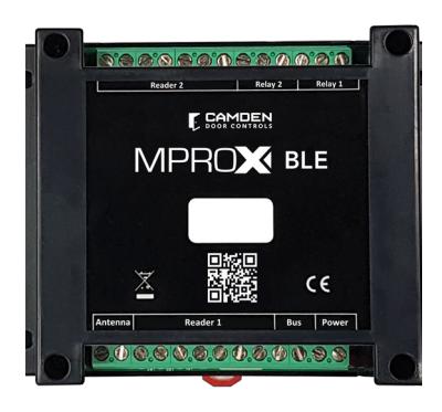
Version: This manual reflects the app version 108 and controller firmware version 1.13. Preceding versions will have some features unavailable.
TABLE OF CONTENTS
| Page Number | |
|---|---|
| Introduction | |
| Technical Features | |
| Feature Table | |
| App Install | |
| Initial Set-Up Programming | |
| Central Setting | |
| History | |
| Scheduling | |
| Relay Commands | 8 |
| • Modes | |
| • Lock and Unlock Schedule | |
| • First person in delay | |
| • Door ajar | |
| User Management | 11 |
| • Adding new users | |
| Adding transmitters | |
| Administration Levels | 14 |
| Data Base Management | 14 |
| Upgrading Controller Firmware | 14 |
| Glossary of Terms | 15 |
| • Anti-passback | |
| • Conditional input | |
| Door position switch | |
| Switches available for electric strike | |
| • Wiegand | |
| Applications | 16 |
| Single door with alarm annunciation | |
| Single door with panic call for assistance and alarm | |
| Single door frictionless solution | |
| •Two door | |
| Vehicle gate entrance | |
| Multiple Controllers with Identical Configuration and Users | 31 |
| Resetting Controller | 31 |
| Compatible Peripherals | 32 |
| Power | 33 |
| Cabinet Assembly | 34 |
| Mechanical Drawing | 34 |
1. INTRODUCTION
The standalone access control CV-603 is easily configured and managed wirelessly with the user-friendly application MProxBLE (Available on iPhone® and Android®). The controller has 2 reader inputs for proximity card readers and a built-in 433MHz receiver for long range two button transmitters. (Model: CX-TXM-2)
It is equipped with two output relays with 1A-capacity contacts for direct connection to electric locks. Connect a MOV or diode provided with the CV-603 controller to the electric strikes or maglocks for reliable operation. The CV-603 has a storage capacity of 2,000 user codes.
- Accelerated enrolling of new credentials into memory (through ID reading via the on-board receiver for transmitters or card readers for proximity credentials wired to the controller)
- Easy deletion of single ID credentials from the memory using quick find tools.
- Quick set-up using predefined output relay modes; bistable/latching or timed operation independently for each relay
- Customizable activation time for each relay (in the timed operation mode)
- Common alarm output available for intrusion notification by configurating the second relay. Any remote notification devices such as an audible horn, strobe or central monitoring module can be wired up.
- The CV-603 controller is available in a DIN rail mountable enclosure or in a wall mounted cabinet with an integrated power supply for indoor installations. For outdoor applications, contact Camden for a lockable NEMA enclosure that houses the 12-volt power supply and provision for a 4 AH battery
2. TECHNICAL FEATURES:
| Power supply | 12VDC |
|---|---|
| Average consumption | < 100 mA |
| Reception frequency for 2 button transmitters | 433Mhz |
| Number of users | 2000 |
| Number of events | 3000 |
| Number of reader inputs | 2 |
| Weigand formats for readers | Wiegand 26, 30,34, 37 bit |
| Number of relay outputs | 2 |
| • |
2
Timed 1-180 seconds |
| Number of relay outputs Types of relay outputs | _ |
| • | Timed 1-180 seconds |
| Types of relay outputs | Timed 1-180 seconds Momentary bi-stable/latching |
| Types of relay outputs Contact capacity | Timed 1-180 seconds Momentary bi-stable/latching 30VDC @ 1 Amp |
| Types of relay outputs Contact capacity Working temperature | Timed 1-180 seconds Momentary bi-stable/latching 30VDC @ 1 Amp -4°F to 131°F (-20°C to +55°C) |
| Types of relay outputs Contact capacity Working temperature DIN rail mount | Timed 1-180 seconds Momentary bi-stable/latching 30VDC @ 1 Amp -4°F to 131°F (-20°C to +55°C) Yes, rail not included |
3. FEATURE TABLE
When a common alarm is required, RELAY 2 is used, therefore it cannot be assigned for a second door.
|
Anti-
Passback |
Alarm | One Door |
Two
Doors |
Request
to Exit |
|
|---|---|---|---|---|---|
|
Anti-
Passback |
Yes | Yes | Yes | Yes | |
| Alarm | Yes | Yes | No | Yes | |
|
One
Door |
Yes | Yes |
Not
Applicable |
Yes | |
|
Two
Doors |
Yes | No |
Not
Applicable |
Yes | |
|
Request
to Exit |
Yes | Yes | Yes | Yes |
CV-603 BLE CONTROLLER REFERENCE MANUAL
INSTALLATION INSTRUCTIONS
4. APP INSTALL
When opening the MProxBLE app, you must grant full permissions to your mobile device files to complete a successful install.
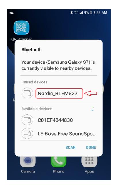
To begin programming, you must first pair via bluetooth to the CV-603 Controller.
Ensure your device Bluetooth is turned on.
For Android devices, a Bluetooth symbol at the top of the screen will indicate the Bluetooth is on.
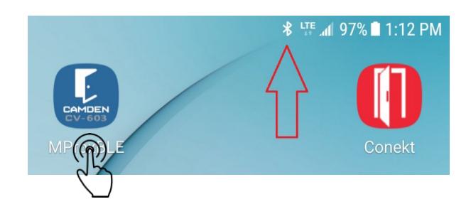
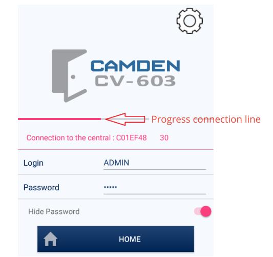
- 1 . Click on the Mprox app to open and display the UPDATE LIST icon.
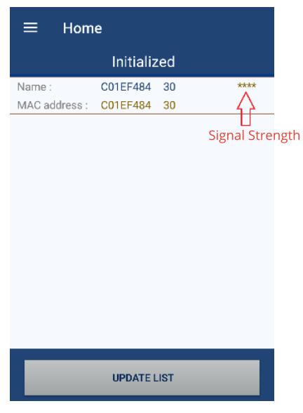
- 2. A default name for your controller and MAC address will appear. The title will state Uninitialized. On the right, star symbols will appear after the name indicating the Bluetooth signal strength between the mobile device and the MProxBLE controller. Ideally, there should be at least two stars for reliable configuration from the app. Reduce the distance between the controller and the mobile device to increase the signal strength.
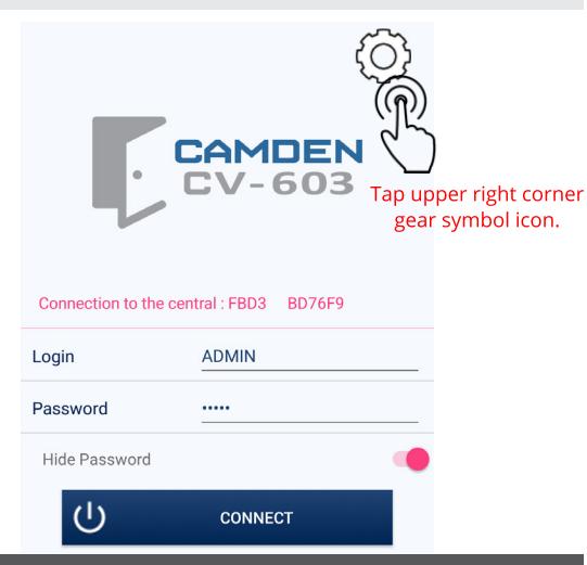
- 3 . Click on the default name and the landing page will appear. After you have been successfully logged into the controller, you can change the name of the controller. Refer to Central setting section 6 if you wish to change the controller name.
- 4. Confirm you have connected to the controller by the connection to the central: (name)' message.
- 5 . A default login (ADMIN) and Password (ADMIN) will appear.
- 6. Click on the CONNECT icon to connect to the controller. A line will scroll from left to right of the screen during this process.
NOTE: If the ---- progress line stops proceeding to the right across the screen, close the app and re-open the app to update list before attempting to connect again.
5. INITIAL SET-UP PROGRAMMING
On initial set-up the app will guide you through a quick set-up process that you can revisit afterwards to edit your selections.
6. CENTRAL SETTING
GENERAL CONFIGURATION:
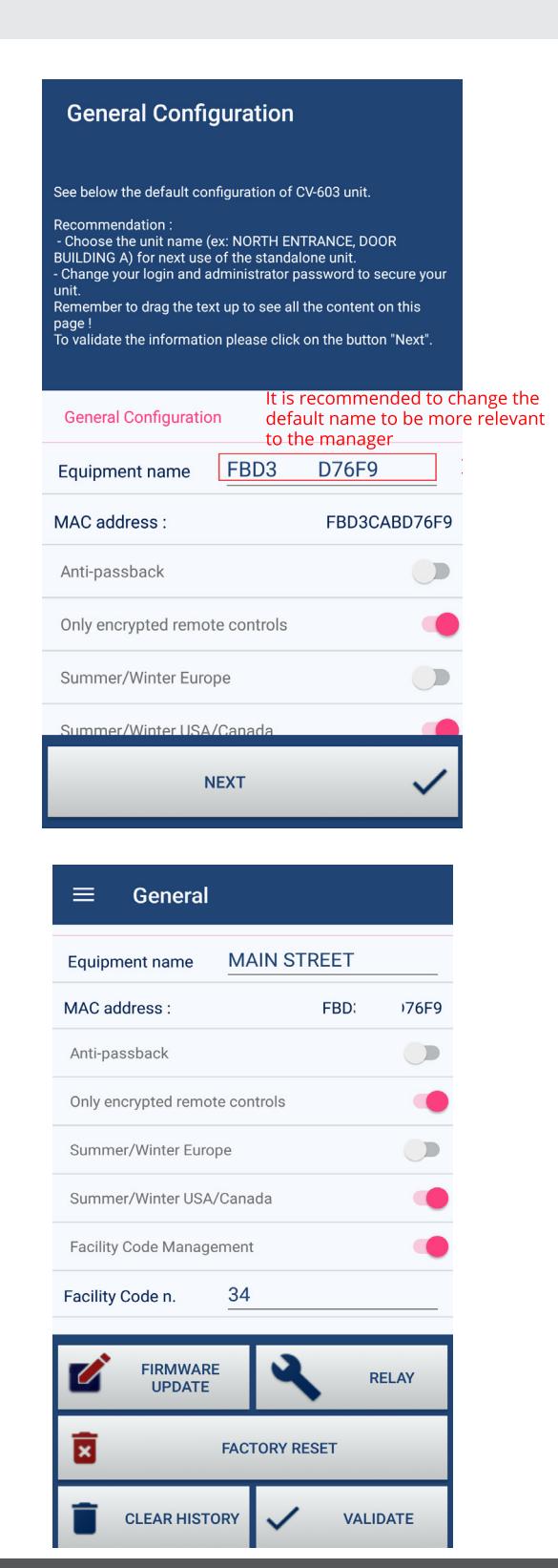
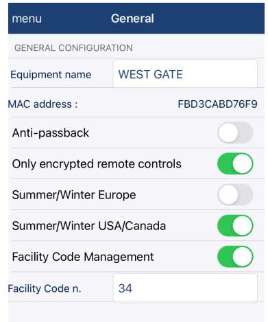
To complete the set-up for your controller that is providing access control, a name should be provided to replace the default number after (Equipment Name). Example: 260 Main Street, or Utility Closet B2 or Stockroom T7 .
Scroll down the page to see the other settings by swiping upwards on the screen.
Anti-passback: If you desire to have anti-pass back, tap the greyed out icon, to turn it on to activate anti-passback for the two-reader controller. Anti-passback prevents users from using their credential twice at the same access point. (see section 9 for explanation of anti-pass back.)
Only encrypted remote controls : The icon on the right should be in the default on position, showing red. Only encrypted two button transmitters (Model: CX-TXM-2) will be accepted by the MProxBLE controller to ensure reliable performance and security.
Summer/Winter USA/Canada: This icon should be on if the region is following day-light savings time to ensure the history reports and schedules are aligned to the local region time.
Facility Code Management: This icon should be on if the card ID numbers are to match the history reports ID designations. Only one facility code number for the CV-603 controller will be accepted.
Enter the value of the facility code number of the cards to be used. (1 to 255, when 26-bit Wiegand formatted cards are used.)
Press NEXT icon at the bottom to save your settings.
CV-603 BLE CONTROLLER REFERENCE MANUAL
INSTALLATION INSTRUCTIONS
7. HISTORY
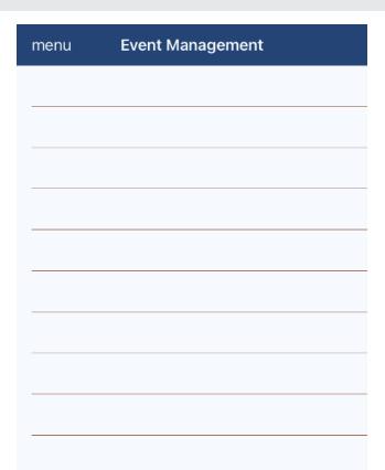
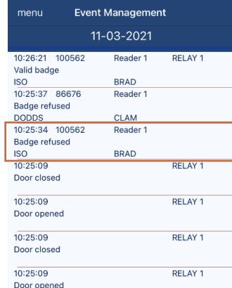
The history function allows access to the database of events such as opening by remote control, smartphone, badge reading or reception of an unknown ID etc...
It is possible to export the list of events in CSV format.
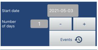
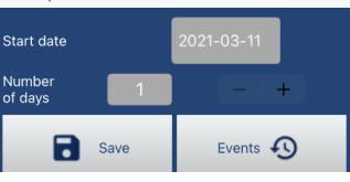
Enter the start date of the history
Select the number of days to be displayed.
Tap on Events icon to refresh the history according to the parameters defined previously.
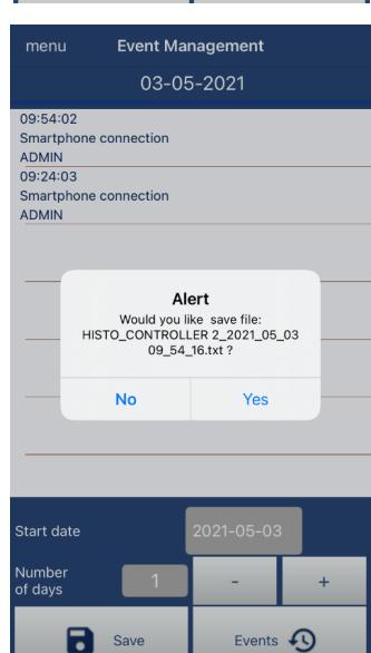
Press Save to export the resulting history.
Confirm the export of the history obtained by tapping Yes on the pop-up Alert message.
You can copy and paste the specific history file from your mobile device file folder to MS Excel® in CSV format to format, filter and print for a permanent record.
Badge Refused: Any credential that shows Badge Refused can be easily added to the User Management data base by simply tapping the line entry from the app history menu. When you tap the specific history line, the app will automatically open the User Management menu section to complete the credential fields of User Family Name and Users Name. Simply tap the ADD icon to add the credential to the user database and its associated permissions.
8. SCHEDULING:
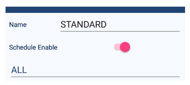
Schedules let you prepare a timetable to determine when certain activities will be permitted to occur. Schedules are prepared and differentiated by name in the app. A default name STANDARD is provided but can be changed to be more relevant to the administrator such as "M to F work week."
Holidays: You can designate up to 12 holidays per year and select if the date is to reoccur every year. Example: January 1st New Years.
Holiday Periods: You can designate up to 5 periods with specific start and end dates.
Special Days: You can designate up to 12 special days year and select if the date is to reoccur every year. Example: Company BBQ August 15th.
Special Periods: You can designate up to 5 periods with specific start and end dates.
Click on the ALL label underlined to select the three display modes.
- 1. ALL
- 2. Monday to Sunday
- 3. Monday to Friday/weekend
Enter up to four time slots T1 to T4 per period by the display mode selected.
To save your settings, click on the VALIDATE icon on the bottom.
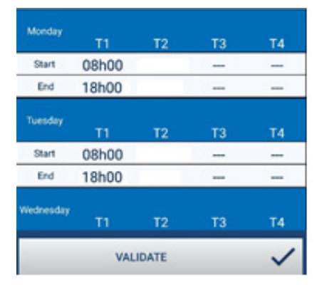
Example of a schedule:
9. RELAY COMMANDS:
The Relay Configuration page will appear.
-
1. Modes:
There are three modes of operation for the Relay 1 and four modes for Relay 2. Relay 1 modes; (i) Momentary, 2 seconds on then off (ii) Timed, a period selectable in hours (0 to 23), minutes (0 to 59) and seconds (0 to 59) (iii) bistable, the relay latches on or off.
-
• BISTABLE (latching) mode:
- ◊ Conditional Input : (Refer to section 9 for more information on Conditional inputs .) Slide this feature ON if the relay can only be triggered when the switch wired to VAL terminals of the controller is normally closed.
- ◊ Scheduling reading ID: Select when a card badge or transmitter can be read to activate the relay. Click on the default schedule setting Always , to pop up the other schedule choices. NEVER and ALWAYS are the default selections.
- ◊ Lock and unlock schedule: Click on the default Never value, to pop up the other choices.
-
• MOMENTARY mode:
Two additional selections appear.
- ◊ Conditional input : If you wish to enable this feature, click on the greyed-out slide switch icon to turn on. This selection will prevent the respective relay to activate unless the controller terminals VAL1 or VAL2 are normally closed.
- ◊ Door Contact: If a door position switch is wired to VAL terminals on the controller, click on the greyed-out slide switch icon to turn on the auto lock back feature. The controller will
-
• BISTABLE (latching) mode:
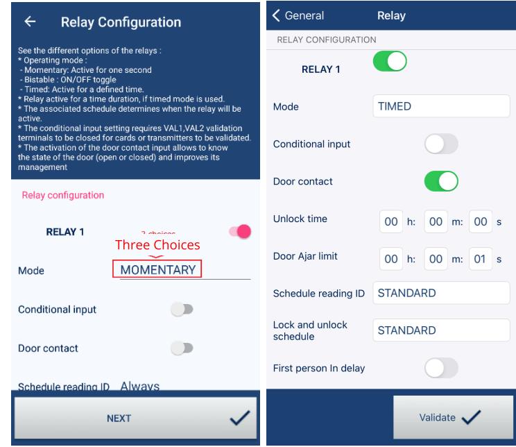
monitor the VAL1 or VAL2 terminals for a door position switch. The auto lock back feature will cause, the door relay energized period to turn off as soon as the door opens enabling the door to be locked as soon as it is returned to the closed position. This feature prevents opportunities of unauthorized personnel from reopening the door during the relay time-period after the door has been closed. A door strike monitor latch can also be used for this purpose. ( Refer to Relay 2 Only mode section _ _ when using this feature is used.)
• TIMED mode: This provides a specific duration the relay can be activated for.
Note: Conditional input and door contact : This functions for all modes except for bistable mode there is no need for a door contact.
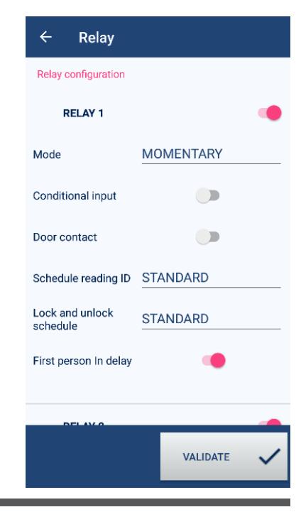
2. Lock and Unlock schedule: click on the schedule when you wish the door to be opened for. It is recommended to select the 'First Person in delay' if the entrance is open to the public.
Note: Schedule reading ID and Lock and unlock schedule are the same as described under BISTABLE mode.
- 3. First person in delay : This selection only appears if NEVER is not selected for the Lock and unlock schedule. This feature activates the relay lock and unlock schedule only after a valid card or transmitter is used for the assigned relay. The purpose of this feature is to not automatically activate the unlock schedule until an authorized credential is used. The property manager may wish to ensure an employee is in the office before opening the gate/door, 9am to 5pm, as an example.
- 4. Door Ajar limit: This feature only appears if the door contact selection is turned on and the mode "timed" is selected. Click this selection to limit the time the door can be held open before an alarm is recorded. This feature is ideal for monitoring doors held open for long periods of time giving opportunities for unauthorized entry. The feature discourages staff from propping open a door, giving opportunities for unauthorized individuals from entering the premises. An alarm condition will occur after the limit has been reached alerting personnel.
RELAY 2 Fourth Mode - ALARM:
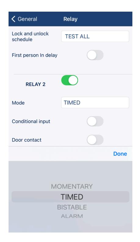
For applications requiring a remote alarm annunciation, relay #2 can be wired to an audible-visual device to alert selective alarm conditions. The controller uses relay 2 form C contact to be used as a switch for a remote annunciating device or monitoring module.
Click on Relay#2 mode field to the right to pop-up relay operating mode choices. You will notice 'Alarm' as an additional mode selection. Click on 'Alarm' to open alarm selections below.
Alarm shut-off period: The duration for Relay #2 selected for 'alarm', can automatically be reset after a predetermined period. It is advisable to have it no less than 4 minutes. Select the period in (h) hours, (m) minutes or (s) seconds for fields to pop open a drop-down selection of values for the time duration.
Door Contact Selection is set to OFF on Relay 1:
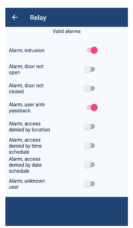
The following alarm conditions are available:
User anti-passback
Access denied by location: Use this to monitor users who are denied entry due to the card reader being used; 1 or 2.
Access denied by time schedule: Use this to monitor users who are denied entry due to the assigned time schedule.
Access denied by date schedule: Use this to monitor users who are denied entry due to the assigned schedule date.
Unknown user: Use this to monitor users who are denied entry using a card or transmitter since they are not in the User data base.
Door contact selection is set to ON for Relay 1:
Additional alarm conditions are available including intrusion. The following alarm conditions are available.
Intrusion: Use this to monitor door forced open cases.
Door not opened: Use this to monitor when relay is energized but the door is not opened.
Door not closed: Use this to monitor when the door is held open after being energized.
Once you have made the selections, click on the VALIDATE icon. A pop-up alert message will appear to confirm your settings have been saved. Click ok to close.
GROUP SETTINGS – User Groups
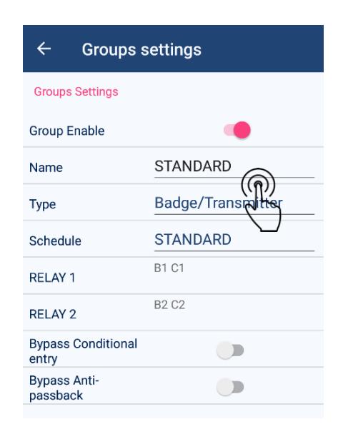
Every user must be assigned to a group. The group management function allows you to administer the operation of the controller according to the parameters of the group(s).
The group function easily applies common configurations to several users.
- 1. Name: To change the name of the group, tap on the default STANDARD name. (up to 17 characters).
-
2. Type:
Tap on the Type default setting Badge/Transmitter and a pop-up selection will appear. Select the type of credential to be used for this group.
- • Badge : Only proximity cards or tags that are compatible to the reader wired to the controller Reader 1 or Reader 2 terminals.
- • Transmitter : Only encrypted CX-TXM-2 two button transmitters can be used that transmits up to 100 feet from the MProxBLE Controller.
- • Badge/Transmitter : Both types of credentials will be accepted.
-
3. Schedule:
Tap on the field right of the schedule label to see one of the three default schedules for the group. Additional selections will be displayed when added to the menu schedules.
- • Always: The group will always be active.
- • Never: The group will never be active
- • Standard: The default time and dates are defined in schedules.
-
4. Relay1 and Relay 2:
Tap on the numbered letters B or C to open the list of signaling devices that can trigger the relay. B represents badges and the number 1 and 2 represents the reader that is permitted to read the badge. C represents the channel and the number 1 through 4 represents the buttons to be used on the transmitter. To be able to choose both readers and the four transmitter channels, ensure the 'type' is set to "badge/transmitter" after clicking on 'validated.'
- Channel 1 to 4 refers to a transmitter's button 1 to 4. Pressing the corresponding button for the active ON channel will trigger the relay. (Currently only two buttons are available.)
- Selecting Reader 1 and/or Reader 2 to determine which reader(s) can trigger the relay.
- 5. Bypass Conditional entry: Turning on this feature by sliding the icon to the right will bypass the conditional requirement for the specific group and therefore bypass the VAL terminals if Conditional input is turned on under the relay from the Relay Configuration. Example: Property manager credentials are not required to have a vehicle present over the loop detector to open the gate.
- 6. Bypass Anti-passback: Turning on this feature by sliding the icon to the right will bypass the anti-passback state for this specific group and therefore bypass the bypass feature under General from the Central settings.
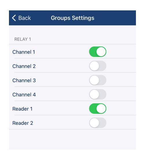
RELAY 1 setting: The illustration shows RELAY 1 will be activated when Channel 1 of a registered transmitter is activated or when a registered badge is read by Reader 1.
10. USERS MANANAGEMENT
Adding New Users:
You can manually enter each Wiegand card number or auto-enroll the ID number. The facility code number entered on Central Setting page must match the card's facility code being entered into the data base. If Camden credentials are used, the facility code will be 34.
Note: If you do not use the same facility code, the credential will be denied access due to an "invalid facility code". You can specify one facility code number or enter zero. A value of zero permits the controller to accept any facility code of a Wiegand credential and only refer to the card number for history or access permissions.
1. Setting up card facility code:
- Go to Central Settings and scroll down to Facility Code Management.
- To enable Facility Code Management, slide the tab to the right.
- The user data base will be configured for Wiegand credentials consisting of a facility code and a card number.
- A Facility Code n. field will appear, enter your cards facility code number.
- One facility code value can be entered. A value of zero will allow any wiegand credential facility code to be used since it will be ignored and only the card number will be referenced.
- Click on "VALIDATE" icon on the bottom right corner
- When the pop-up Alert message configuration saved appears, this confirms your entry has been accepted.
- Click OK to close.
- Click on the menu icon (3 horizontal bars on android devices.) on the upper left corner to return to the main menu. 'successfully added' will appear. Press OK to close.
2. Manually by entering ID numbers
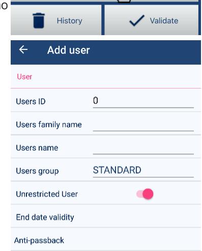
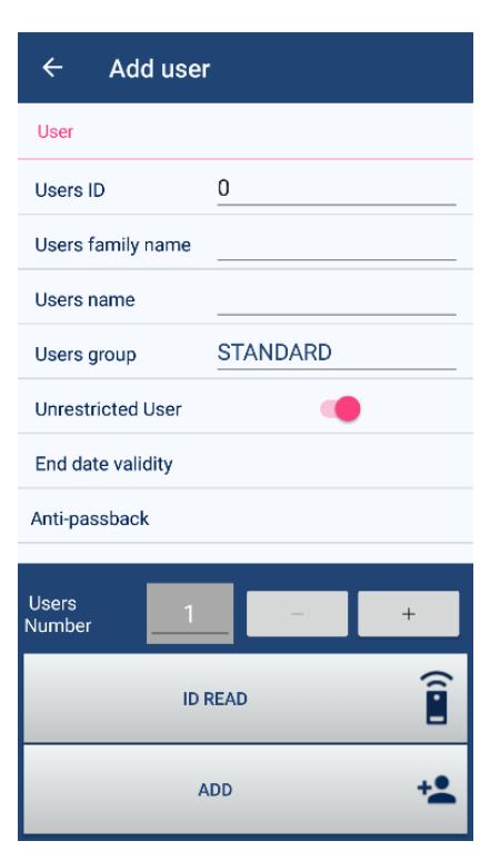
- Click on the icon ADD USER. Enter the Users ID number you wish to add, enter the family and user's name.
- If the facility code has been set to zero, simply enter the Wiegand card numbers. When the batch of cards to be added consists of multiple facility codes, set the facility code value to zero for easy card number entries.
- Select the User Group from the selections.
- Slide the Unrestricted icon to the right to if the User for this assigned ID number will have no restrictions by time, date or condition.
- Enter the end date to accept the credential in the End date validity field.
- Slide the icon to the right if this ID will have anti-pass back restrictions.
- When all the fields have been edited, click on the Add+ icon
3. Bulk add a sequence of card IDs
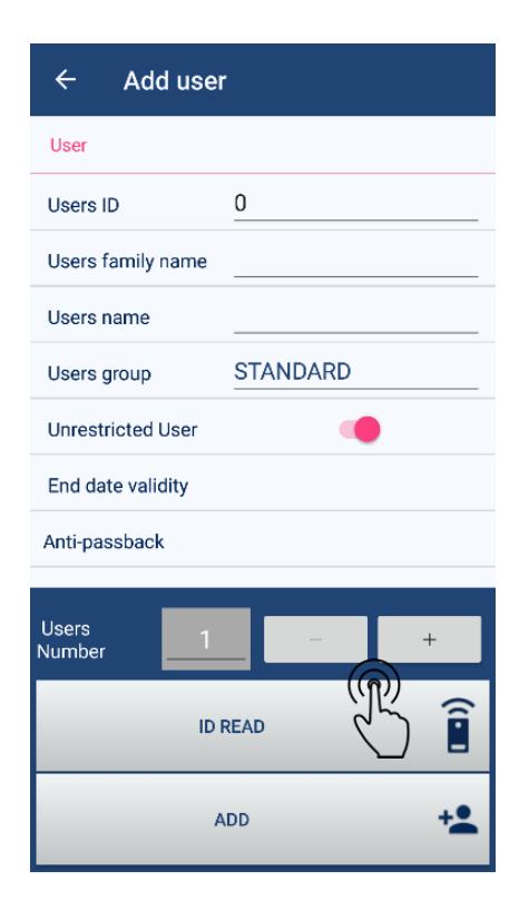
- Enter the start card ID of the batch. The app will batch load the remainder quantity of card IDs in sequence.
- Click on the + icon or enter the quantity of card badges of the Users Numbers to be added.
- Enter the smallest ID number of the sequencial bulk numbers you wish to add.
- Tap the ADD icon. A confirmation pop up message 'The user has been successfully added' will appear. Press OK to close.
- Go back to add the unique family and users name to each of the bulk credentials you just added. Click on the Search by ID to quickly start adding the family and user's name. When the name fields have been edited,
- click on the Validate icon to save it.
Adding Transmitters: Follow the same procedure in section 2 and 3 above for adding one or many transmitters but press one of the push buttons to transmit the ID code to the controller. Make sure you are within range of the receiver, under 100 feet for the app to accept the transmitter code. The red LED on the controller will illuminate when the push button is pressed on the transmitter confirming the receiver got the transmission. Button #1 and #2 are preassigned to RELAY1 and RELAY2 for entry and exit respectively.
4. Automatic Enrollment by reading a credential:
- Prepare to present the credential in front of the card reader.
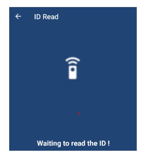
- press ID READ icon to trigger the controller to read the card ID by presenting the card in front of the card reader. Pressing the ID Read icon shall activate the unit to read the credential presented to the card reader and automatically place the credential code it read into the User ID field. The card reader will beep if it read the credential. If the card reader did not beep, the card cannot be read by the reader and therefore cannot be added to the data base. (See section _ _ about compatible credentials and readers.)
- Simply enter the remaining data fields for family name, username, users group.
- Press ADD icon.
- A confirmation pop up message 'The user has been successfully added' will appear. Press OK to close.
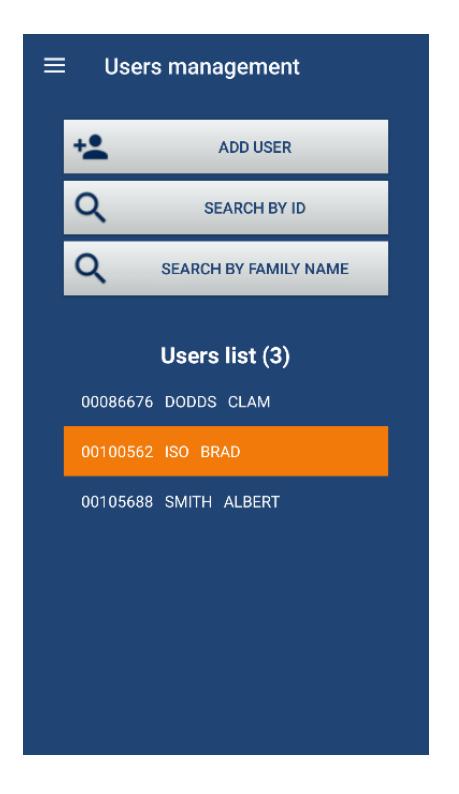
- On the User Management main page, you will see the user list displaying all the entries you made with a sum total.
5. Search by ID:
- You can search by ID number by clicking on the search by ID icon.
- The next page you can enter the value to the right of the search icon at the top of the page.
- Tap on the search icon to the left to display the user information you are seeking. From here you can;
- Make edits to the user profile from here and press the validate icon once finished or
- Delete the user.
- If you have the credential, you can use the ID read icon by presenting the credential in front of the reader or pressing the transmitter button. Since the app will automatically log out after 5 minutes of inactivity, you must present the credential before it logs out to see the user profile. Use the ID read icon if the card reader is close by that you can return under 5 minutes.
6. Search by Family Name;
- Enter the family name by clicking on the search by Family Name icon.
- Click on the search icon at the top after entering the name to be search to the right of the icon. If the name is in the data base, it will appear.
- Similarly using search by ID, you can make edits or delete the user profile.
7. Assigning Users Group:
- In each user profile you can assign one of the user groups you previously set up by tapping on the field right of the Users Group label. A drop down selection will appear of all the groups you previously configured.
- Select the group for the user then tap validate to save.
8. End Date Validity
- If you successfully unselect Unrestricted User the slide switch will turn from red to grey.
- Tap the date right of the End date validity label to pop open a calendar where you can select the end date for the credential assigned to the user.
9. Anti-passback:
• If you are using the anti-passback feature, status of the user will be displayed here.
There are 3 anti-pass back statuses for every user.
Entering : The user can only be accepted on 'exiting' the access point.
Exiting : The user can only be accepted on entering an access point.
Unknown : The user can be accepted on 'entering' or 'exiting' an access point.
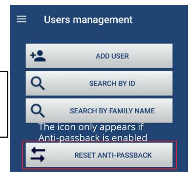
When you create a credential: its first anti-passback status is «unknown»: it will be accepted in either direction of travel at the access point. As soon as it is accepted on a reader/ receiver it loses its "unknown" state and enters the cycle of anti-passback.
When powering up the MProxBLE, all users systematically switch to an "unknown" state of anti-passback.
Once user information has been added, you will be able to see the ID number and name on the User Management page. You will be able to tap directly the ID number and user name to quickly edit the information.
CV-603 BLE CONTROLLER REFERENCE MANUAL
INSTALLATION INSTRUCTIONS
11. ADMINISTRATION LEVELS (5)
You can restrict some administrators from viewing or editing portions of the configurating tool to simplify their daily responsibilities. Administrators will login with
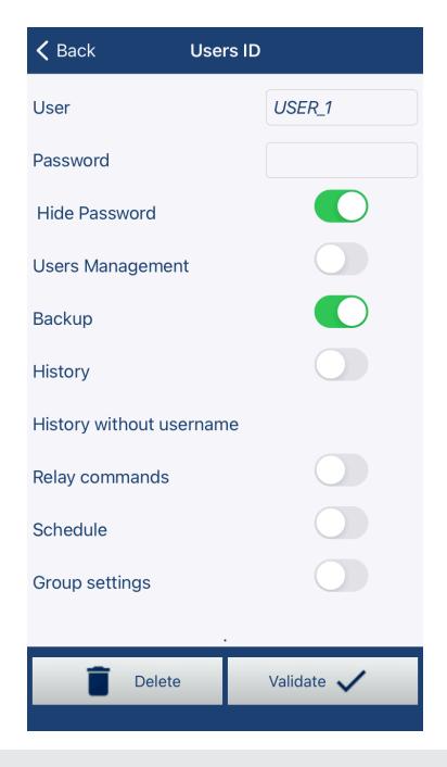
- 1. Click on the Session Management icon from the main menu to display the five administrator user levels. The top ADMIN level is a default setting and cannot be configured. Here you can change the admin password. If you forget the password it cannot be retrieved, and you will need to set the app to the factory default and erase all your data. All the remaining five levels are configurable.
-
2.
User ID
selections. The following menu selections can be removed by admin user. To activate the 5 sub-admin levels, one of the selections must be chosen and validated.
- User Management
- Backup
- History
- History without username
- Relay Commands
- Schedule
- Group Settings
12. DATA BASE MANAGEMENT
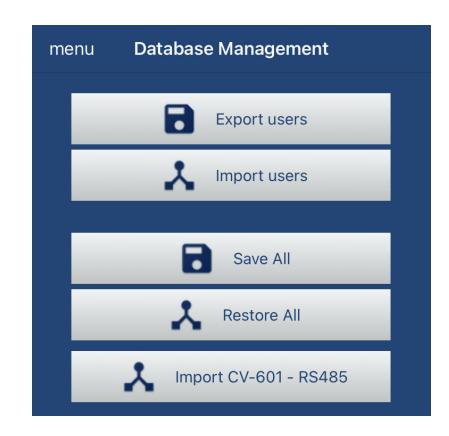
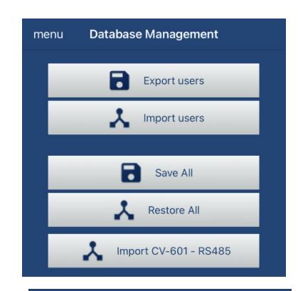
It is possible to export and import users by tapping on the Back up icon from the main menu.
These files are typically saved in your mobile device document files. The csv file names are automatically assigned by type and date.
It is highly advisable to backup your data by selecting SAVE ALL once you have finished configuring the MPRoxBLE control unit. If the unit is damaged by lightning or unintentionally erased by factory reset, you can select RESTORE ALL from this menu section. It is advisable to copy the files to another device in case the current devices is lost, broken or stolen.
Import CV-601 icon is for an obsolete controller that could be upgraded to the current MProxBLE with a RS-485 adaptor.
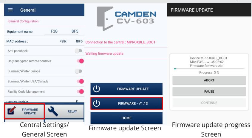
13. UPGRADING CONTROLLER FIRMWARE (FIRMWARE UPGRADES ARE ONLY POSSIBLE FROM THE ANDROID APP)
Your device must be connected to the Internet.
- 1. Tap on the Central Settings icon in the main menu.
- 2. The General screen will appear.
- 3. Tap the FIRMWARE UPDATE icon.
- 4. Tap Firmware V 1.13 to get the latest version for the MProxBLE controller.
- 5. Wait for the new firmware to load into the MProxBLE controller.
- 6. Restart the app after waiting for the upgrade to complete its process.
- 7. You can now resume using the MProxBLE configuration app as previously. Central Settings/
14. GLOSSARY OF TERMS
ANTI-PASSBACK:
Hard anti-passback: Users will be restricted from passing their credential, 'pass back', to let their associate gain entry because once they have entered, the system knows that they are inside and won't let them re-enter unless they first exit. Hard anti-passback maintains a high level of security but may inconvenience users who forget to use their card to enter or exit (by following someone else in). The system will have their status confused in the system if they do not badge in AND out, it will think that they are outside when they are inside, and so will not let them leave. Administrators can 'reset' the state of anti-passback using the MProx app.
Notes:
-
Transmitter versus proximity credentials:
- ◊ Two button transmitter The button #1 and #2 are preassigned to RELAY1 and RELAY2 for entry and exit.
- ◊ Proximity credentials You can use RELAY1 for access control and RELAY2 for alarm.
- Reader 1 is designated as 'entry' and Reader 2 is designated as 'exiting' under User Management anti-passback field.
-
When you create a badge: its Anti-passback status is «unknown»: it can be accepted indifferently the first time on an incoming or outgoing reader. As soon as it is accepted on a reader it loses its "unknown" state and enters the cycle of antipassback.
- ◊ When the badge is accepted on an "entering" reader (reader 1), its state of Anti-passback is "exiting", means that it can only be accepted on an "exiting" reader
- ◊ When the badge is accepted on an "exiting" reader (reader 2), its anti-passback state is "entering" state means that it can only be accepted on an "entering" reader
- ◊ When powering up the MProxBLE, all users systematically switch to an "unknown" state of anti-passback.
- ◊ Alarm Output: RELAY2 is used for common alarm notifications when selected. Door contact for RELAY 1 must be selected before any of the intrusion features to appear to select for alarm notification.
CONDITIONAL INPUT:
Validates that a vehicle is in close proximity of a barrier gate or overhead door to prevent tail gating opportunities of unauthorized vehicles entering the property. The VAL1 and VAL2 validation terminals on the controller are wired to a beam detector to ensure the vehicle is directly in front of the barrier gate.
DOOR POSITION SWITCH: (DOOR CONTACT)
For access control, 'door position switches', also called 'DPS', 'latch monitors', or 'door sensors', detect whether a door is opened or closed. Door position switches work by using magnets and a magnetic sensitive switch. A magnet is placed in the top of the door and the switch is placed in the door frame. When the door is closed, the switch rests in a "balanced-bias" magnetic field of several magnets (including the magnet on the door and others within the switch). When the door opens, this unstable magnetic field is disrupted, opening the switch. The normally closed switch circuit is monitored by the controller thus attempts to cut the wiring to bypass the switch can also set it off. Other versions of these switches are available for overhead roll-up doors.
The method of sensing is simple: when a door is shut, the circuit is complete. However, when the door opens, the circuit breaks open, signaling to the access system the door is not closed. Since doors cannot be locked or 'secured' when opened, this sensor describes where a facility is most vulnerable.
Installers who do not install DPS in order to 'save costs' or otherwise consider DPS optional, is critically compromising the security. Without a DPS, the access controller cannot be verified 'controlled' at all, and installing DPS should be a mandatory aspect of every opening.
It is best to conceal the switch and magnet in the frame at the top of the door. Surface mounting DPS can be used on doors in rough finish areas. If the monitoring DPS device can be seen with the gate or door closed, it can be exploited.
There are a wide range of door position monitors and switches on the market to provide status and information as to the state of the door and latch bolts.
CV-603 BLE CONTROLLER REFERENCE MANUAL
INSTALLATION INSTRUCTIONS
Switches Available for Electric Strikes
Latch-Bolt Monitoring Switch: Electric Strikes can often be ordered with a latch bolt position switch, which many use like a door position switch to determine if the door is open or closed. Please note that the latch bolt position sensor is not equivalent to the door position switch. It is possible to place a wad of paper in the latch pocket holding the latch bolt position sensor closed, thus fooling the access control system into thinking that the door is closed when it is actually open.
Dead-Bolt Monitoring Switch: Electric Strikes built to accommodate mechanical locks with dead-bolts may also be equipped with a dead-bolt position monitoring switch.
Lock Status Monitoring Switch: This switch identifies the condition of the electric strike's locking mechanism, telling the Access Control System if the strike is locked or unlocked.
Exercise caution when modifying an existing door frame to accept an electric strike to be certain that you are not doing so on a fire-rated door frame. Such a modification would void the fire rating of the frame.
WIEGAND
Wiegand is the trade name for a technology used in card readers and sensors in access control products. A card is read by bringing it near, a device called a Wiegand proximity sensor. The term Wiegand originally referred to card reader technology which included the encoded credential, the reader and the interface (data communications format) between the reader and the access control electronics.
The "26-bit" refers to the protocol of the data on the card. Proximity credentials and readers typically use the Wiegand interface and 26-bit encoding. In access control 26-bit is the industry standard, open encoding format. The data encoded using 26-bit format consists of 255 possible facility codes and within each there is a total of 65,535 unique card numbers. Every card has a consecutive serial number encoded, assigned in your access control database to a cardholder. For 26 bit cards, it can go from 0 to 65,535. The card number is the read, and compared to that database, to allow or deny access. But, what if two companies have the same card numbers? They could access each other´s premises.
To reduce this risk, a second number, know as facility or site code is encoded into each card. This number can go from 0 to 255 on a 26-bit format card. To grant access, an access control system validates the facility code AND the serial number. Company A will reject Company B cards, and vice versa, even if they have the same card serial number, because the facility code does not match.
To reduce the chances of having duplicate codes, the industry has adopted larger bit formats including 34 and 37 which Camden Control uses.
15. APPLICATIONS
The following are typical applications for the MProxBLE.
- A. Small office, shed or retail store A locked door with scheduling will lessen the burden for key keepers by using a card reader. Proximity credentials are less costly to replace if they are lost or stolen. Administrators can select what conditions shall emit an alarm to secure their interests.
- B. Private washroom The single door application with a call for assistance will conveniently manage locked washrooms. Managers can control entry using a long range two button transmitter or issue credentials to users wishing to gain entry. Misuse of the washroom can be monitored and if assistance is required, an alarm can be sent.
- C. No Touch Access Control Using Camden's miniature CX-12PLUS module and the CM-RQE70 detector, it is easy to integrate automatic door operators to provide a touchless access control solution.
- D. Barrier vehicle gates The built-in 433 MHz receiver can accept long range two button transmitters for vehicle access with all the added benefits of access control scheduling and access group levels. Hard anti-pass back is providing for strict parking control with validation loop detector inputs. Two relays enable the ability to incorporate a pedestrian gate as well as a vehicle gate with specific credential permissions and scheduling control.
Single Door Access with Alarm Annunciation
The system components consist of:
| Camden Model# | Camden Model# | |||
|---|---|---|---|---|
| Item | Description | Quantity | CV-603PS-K1 | CV-603 |
| 1 | Controller | 1 | CV-603 provided in kit | CV-603 |
| 2 | DC Power Supply | 1 | 60-69B002 - provided in kit | PS-13 |
| 3 | Transformer | 1 | CX-TRP-4016 provided in kit | CX-TRP-4016 |
| 4 | Alarm Annunciator | 1 | CM-AF142SO | CM-AF142SO |
| 5 | Door Strike, 12 VDC | 1 | CX-ED1079 | CX-ED1079 |
| 6 | Door Position Switch, a door latch monitor switch can be used, add suffix "L" to CX-ED1079 | 1 | CX-MDA surface or CX-MDH recessed. | CX-MDA surface or CX-MDH recessed. |
| 7 | Proximity Card Reader, 125 KHz. Not required if transmitters are used. | 1 | CV-7400 | CV-7400 |
| 8 | Request to Exit Device | 1 | CM-RQE70 PIR sensor or CM-30E Push button. | CM-RQE70 PIR sensor or CM-30E Push button. |
Substitutions:
- a) The alarm annunciator can be replaced with any remote alerting device. If you are using the 12 VDC power supply provided, check your power consumption calculations. Relay 2 contacts switches the remote annunciator, and the duration can be configured with the app.
- b) Request to Exit Switch can be replaced with any normally open, momentary push button switch or a CM-RQE70 PIR REX detector to automate the exit request.
System Operation:
- a) The door is normally locked and closed. The door position switch confirms when the door is closed.
- b) A user presents a card credential in front of the card reader. The card reader's red LED indicates it is powered. When the credential is within 2 inches, the reader will beep, and the controller red LED will pulse on 1 second to confirm the credential data was received. If the controller red LED blinks twice, the credential is being denied by the controller.
- c) If the credential is approved by the controller, the door strike will energize for the pre-set period duration. The door strike will energize for the full duration of the period until the door is opened and the door position changes state. As soon as the door is opened, the door strike shall turn off securing the door as soon as it closes.
- d) Users exiting the door, must be detected by the request to exit device; manually by a push switch or automatically using a PIR detector. Opening the door without a request to exit switch shall cause the controller to generate a door forced open alarm.
-
e)
An alarm annunciator shall be triggered for the following selected alarm conditions.
- a. Intrusion
- b. Door not opened after an approved credential read.
- c. Door not closed after access. Alerts managers when the door is being left open.
- d. Anti-passback
- e. Access denied by location Attempts made by credentials not approved by either reader 1, channel 1, reader 2 or channel 2.
- f. Access denied by schedule.
- g. Unknown user a credential not enrolled into the controller user data base.
- f) Administrators shall use the app to control and configure the CV-603 controller using wireless Bluetooth. A steady on blue LED on the controller will confirm the connection.
Single Door Access with Alarm Annunciation
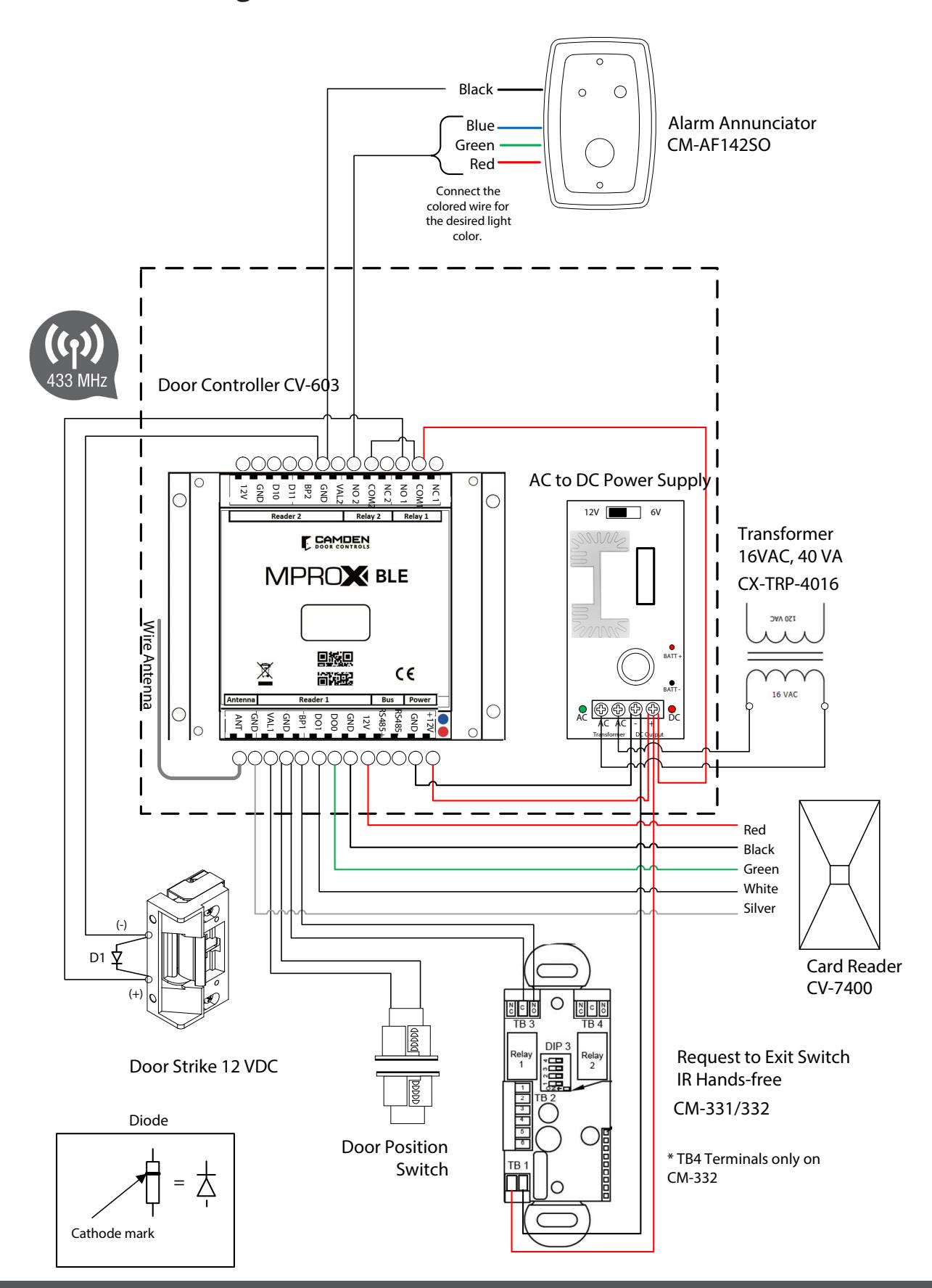
Single Door Access with Alarm Annunciation
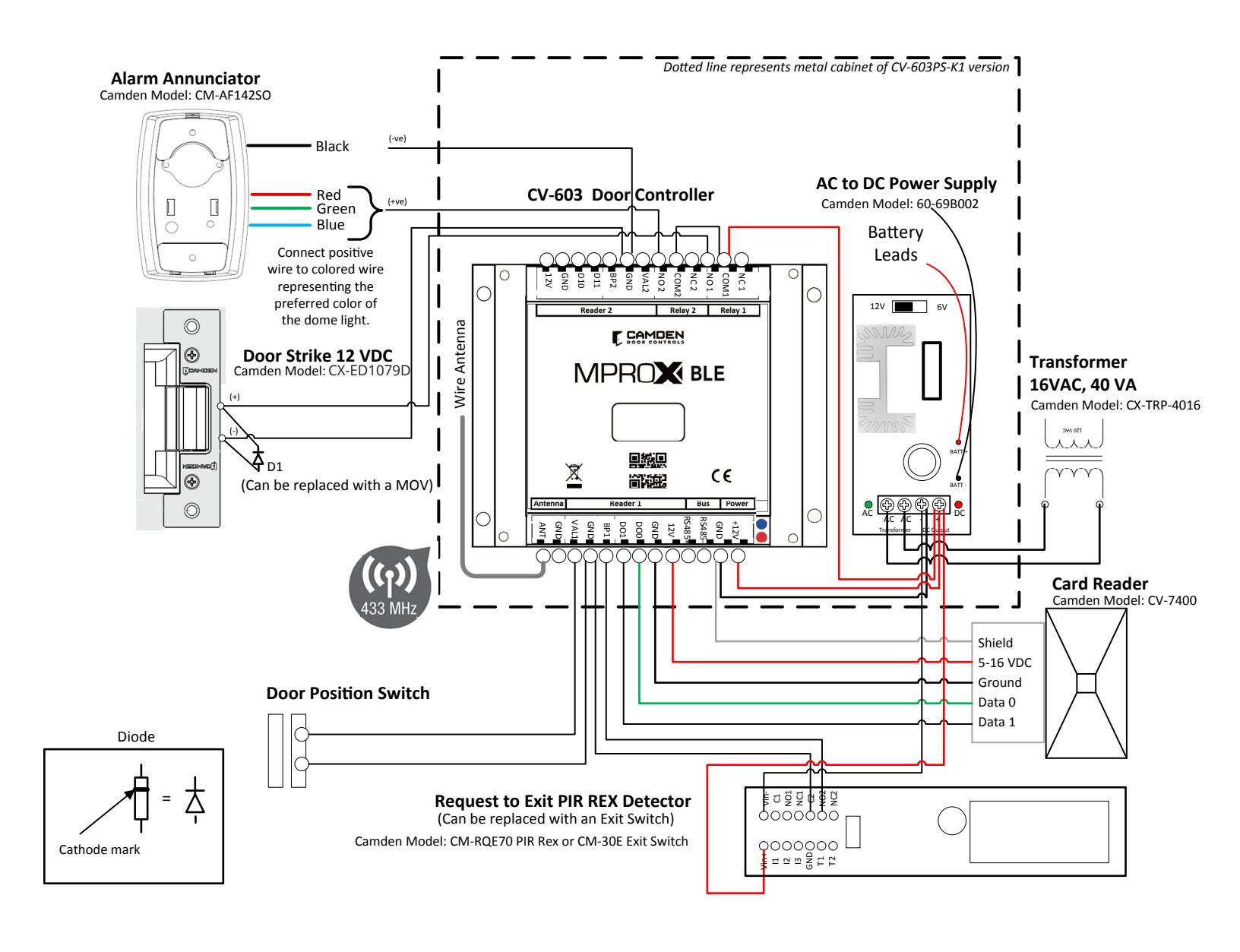
Single Door Access with ALARM Annunciation
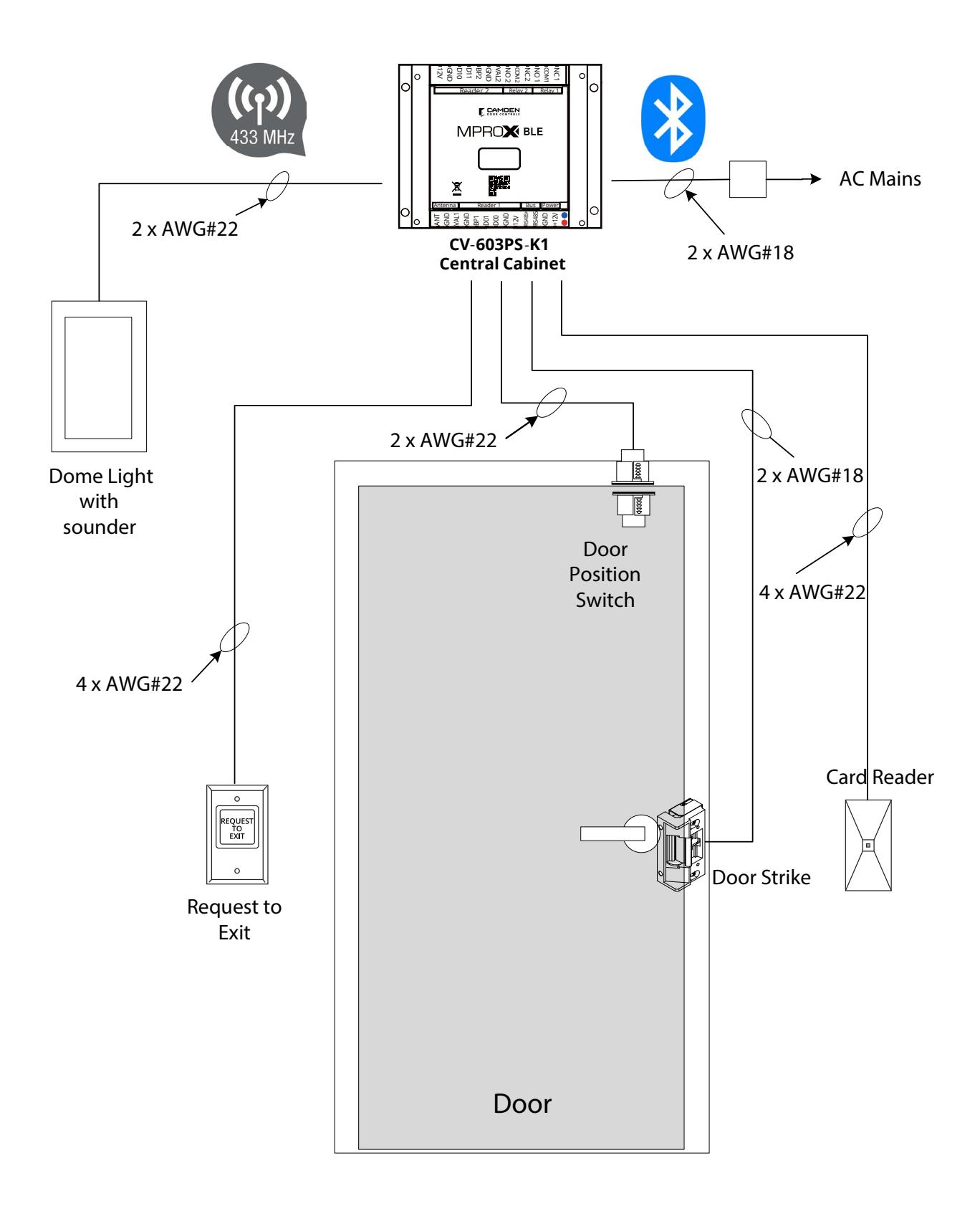
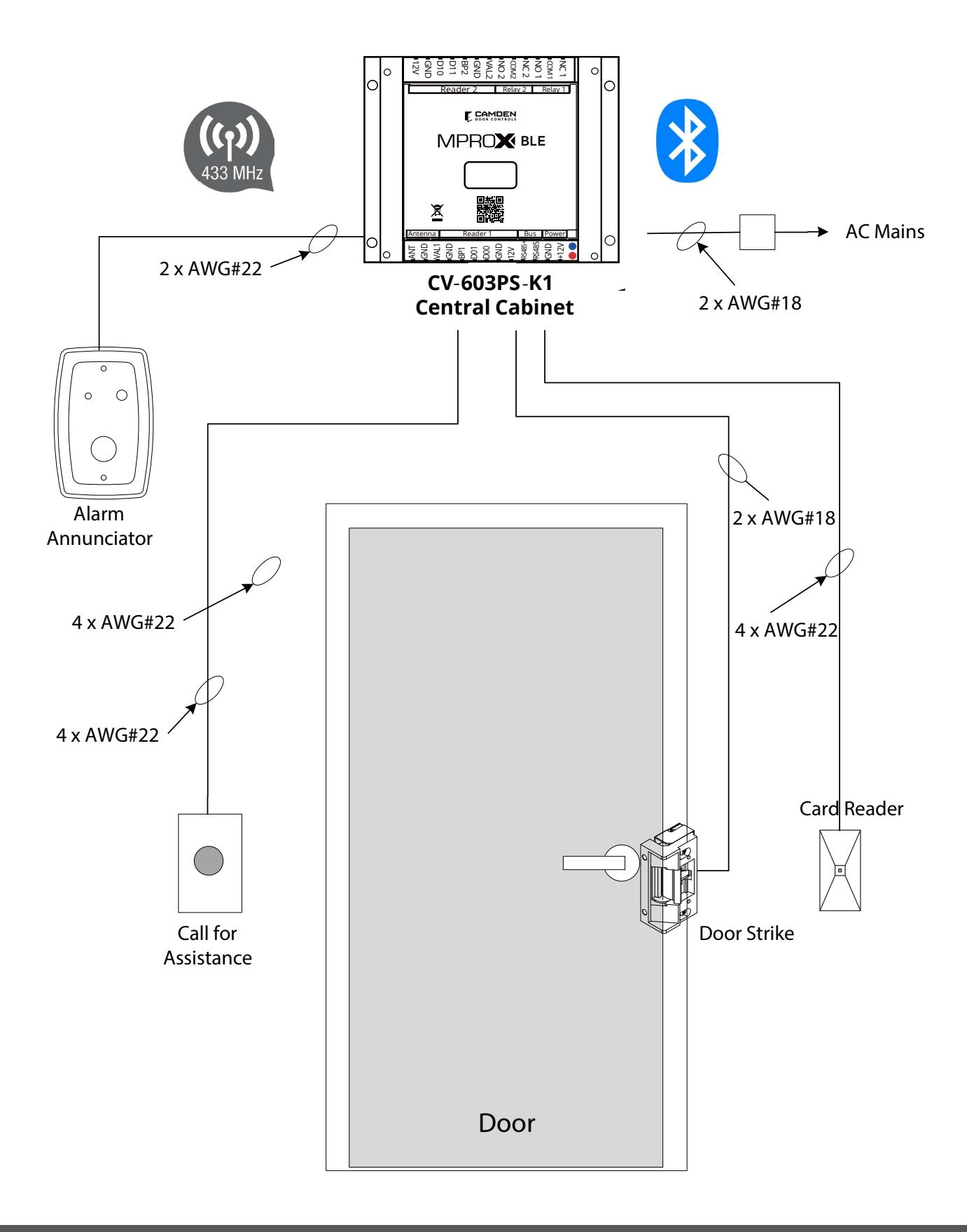
Single Door Access and call for assistance using an alarm annunciator
The system components consist of:
| Item | Description | Quantity | Camden Model # |
|---|---|---|---|
| 1 | Central Control Cabinet with power supply | 1 | CV-603PS-K1 |
| 2 | Alarm Annunciator | 1 | CM-AF142SO |
| 3 | Door Strike, 12 VDC | 1 | CX-ED1079 |
| 4 | Call for assistance Switch, Alarm | 1 | CM-30U |
| 5 | Wiegand Card Reader | 1 | CV-7400 |
| 6 | Request to Exit Switch | 1 |
CM-RQE70 or CM-30E or
CM-331/332 |
Substitutions:
The alarm annunciator can be replaced with any remote alerting device. If you are using the 12 VDC power supply provided, check your power consumption calculations. Relay 2 contacts switch the remote annunciator, and the duration can be configured with the app.
System Operation:
- a) The door is normally locked and closed. The door position switch confirms when the door is closed.
- b) A user presents a card credential in front of the card reader. The card reader's red LED indicates it is powered. When the credential is within 2 inches, the reader will beep, and the controller red LED will pulse on 1 second to confirm the credential data was received. If the controller red LED blinks twice, the credential is being denied by the controller.
- c) If the credential is approved by the controller, the door strike will energize for the pre-set period duration. The door strike will energize for the full duration of the period.
- d) Users exiting the door, must be detected by the request to exit device; manually by a push switch or automatically using a PIR detector. Opening the door without a request to exit switch shall cause the controller to generate an alarm.
-
e)
An alarm annunciator shall be triggered for the following selected alarm conditions.
- a. Intrusion
- b. Door not opened after an approved credential read.
- c. Door not closed after access. Alerts managers when the door is being left open.
- d. Anti-passback
- e. Access denied by location Attempts made by credentials not approved by either reader 1, channel 1, reader 2 or channel 2.
- f. Access denied by schedule.
- g. Unknown user a credential not enrolled into the controller user data base.
- f) Administrators shall use the app to control and configure the CV-603 controller using wireless Bluetooth. A steady on blue LED on the controller will confirm the connection.
Single Door Access and call for assistance using an Alarm Annunciator
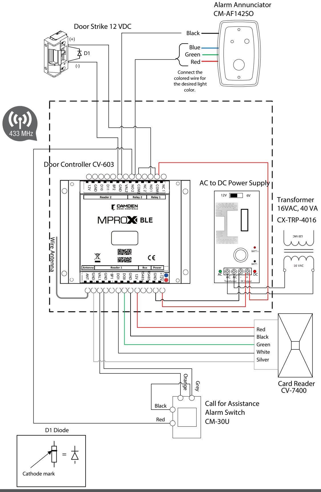
Single Door Access and call for assistance using an Alarm Annunciator
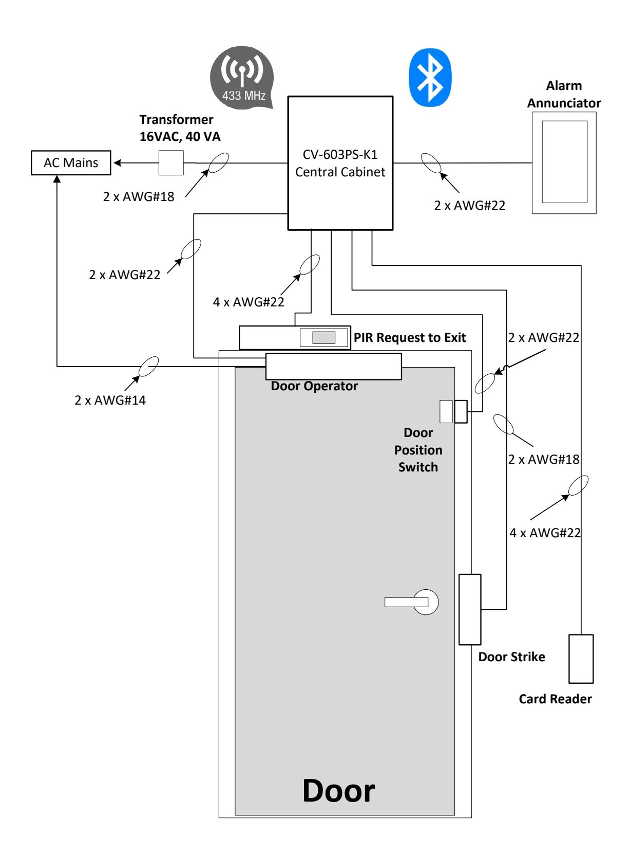
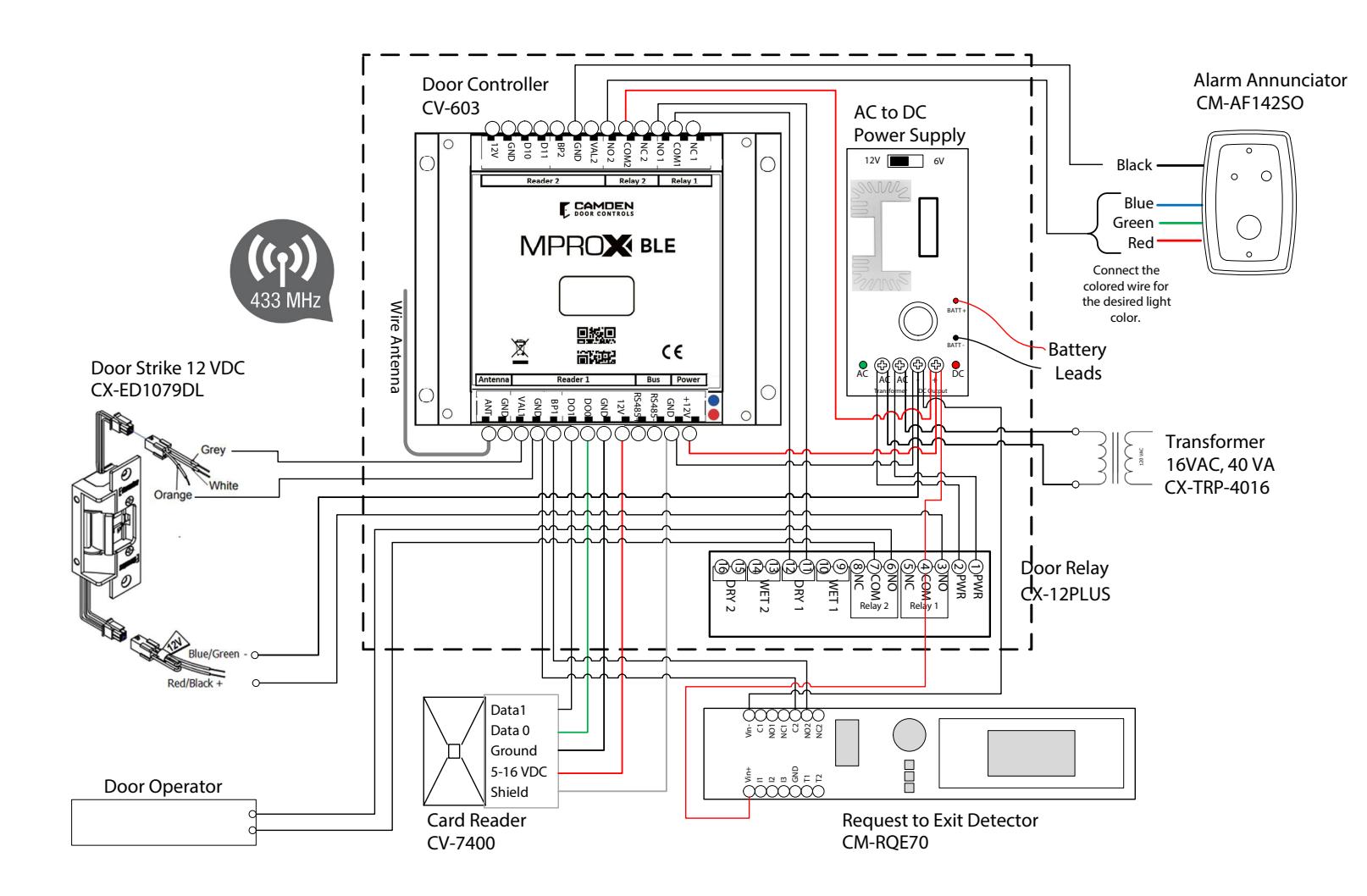
Single Door Access with automatic door operator and alarm annunciation (Frictionless Solution)
The system components consist of:
| Item | Description | Quantity | Camden Model # |
|---|---|---|---|
| 1 | Central Control Cabinet with power supply | 1 | CV-603PS-K1 |
| 2 | Alarm Annunciator | 1 | CM-AF142SO |
| 3 | Door Strike, 12 VDC | 1 | CX-ED1079 |
| 4 | Door Position Switch (a door strike monitor latch can be substituted.) | 1 | CX-MDA or CX-MDH |
| 5 | Wiegand Card Reader | 1 | CV-7400 |
| 6 | Request to Exit PIR Detector | 1 | CM-RQE70 |
| 7 | Automatic Door Relay module | 1 | CX-12PLUS |
Substitutions:
- a. The Alarm Annunciator can be replaced with any remote alerting device. If you are using the 12 VDC power supply provided, check your power consumption calculations. Relay 2 contacts switches the remote annunciator, and the duration can be configured with the app.
- b. Request to Exit Switch can be replaced with any normally open, momentary push button switch or a CM-RQE70 PIR REX detector to automate the exit request.
System Operation:
- a) The door is normally locked and closed. The door position switch confirms when the door is closed.
- b) A user presents a card credential in front of the card reader. The card reader's red LED indicates it is powered. When the credential is within 2 inches, the reader will beep, and the controller red LED will pulse on 1 second to confirm the credential data was received. If the controller red LED blinks twice, the credential is being denied by the controller.
- c) If the credential is approved by the controller, the door strike will energize for the pre-set period duration. The automatic door operator will activate after the door strike is energized and stay open for the pre-set period of time.
- d) Users exiting the door, must be detected by the request to exit device; manually by a push switch or automatically using a PIR detector.
Caution: Users opening the door from inside without pressing the request to exit switch shall cause the controller to generate a door forced open alarm. To prevent false alarms, prevent the inside door handle from retracting the door latch forcing users to use the request to exit button. Using the PIR detector will automate the exit process and prevent the necessity to press a request to exit button.
-
e)
An alarm annunciator shall be triggered for the following selected alarm conditions.
- a. Intrusion
- b. Door not opened after an approved credential read.
- c. Door not closed after access. Alerts managers when the door is being left open.
- d. Anti-passback
- e. Access denied by location Attempts made by credentials not approved by either reader 1, channel 1, reader 2 or channel 2.
- f. Access denied by schedule.
- g. Unknown user a credential not enrolled into the controller user data base.
- f) Administrators shall use the app to control and configure the CV-603 controller using wireless Bluetooth. A steady ON blue LED on the controller confirms there is a communication connection between the mobile device and the controller.
Single Door Access Control Frictionless Solution
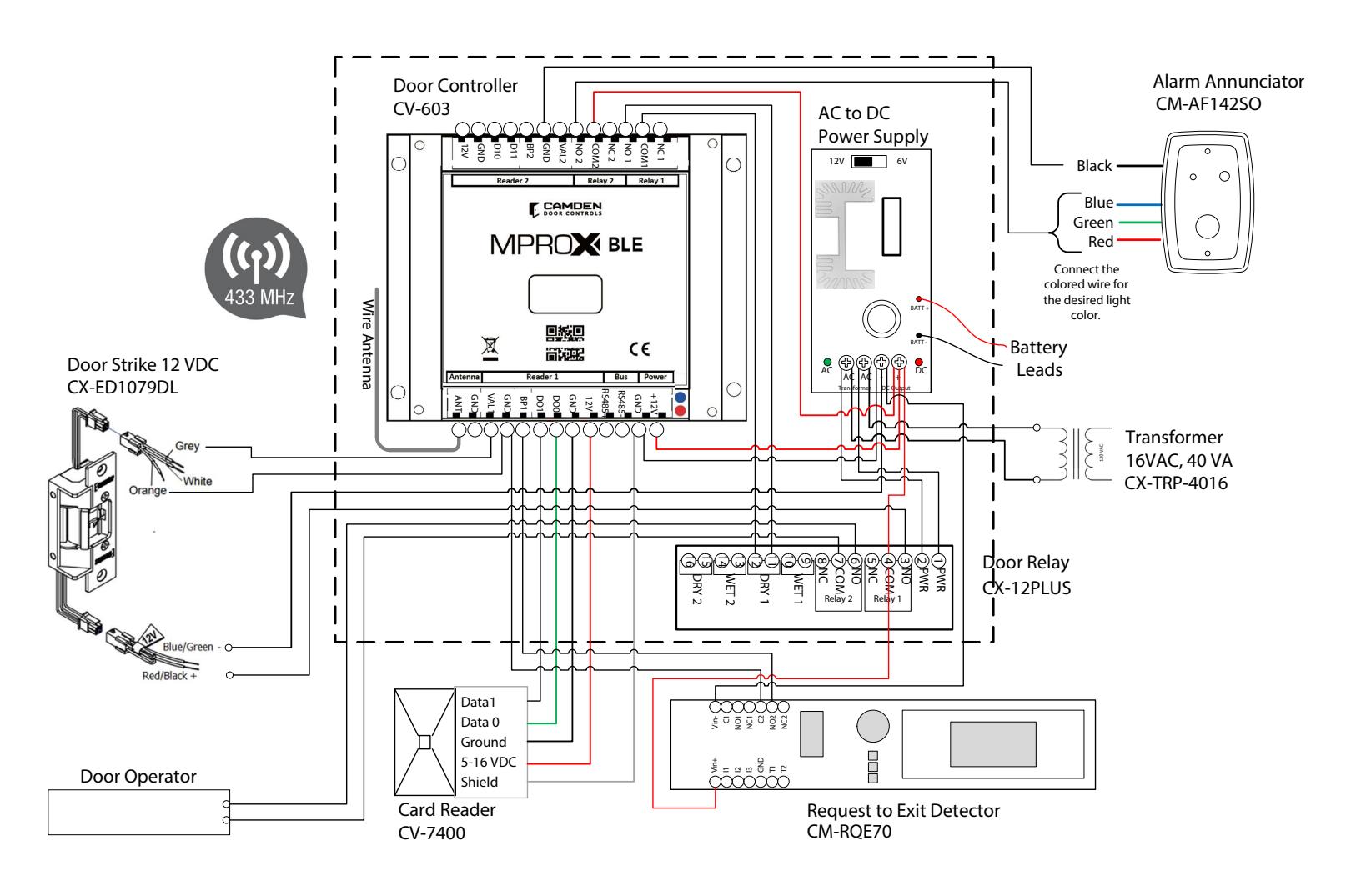
SINGLE DOOR ACCESS CONTROL Single Door Access Control Frictionless Solution
Two Door Access
The system components consist of:
| Item | Description | Quantity | Camden Model # |
|---|---|---|---|
| 1 | Central Control Cabinet with power supply | 1 | CV-603PS-K1 |
| 2 | Door Strike, 12 VDC | 2 | CX-ED1079 |
| 3 |
Door Position Switch, (a door strike monitor latch can be substi
tuted.) |
2 | CX-MDA or CX-MDH |
| 4 | Wiegand Card Reader | 2 | CV-7400 |
| 5 | Request to Exit Switch | 2 |
CM-RQE70 or CM-30E or CM
331/332 |
System Operation:
- a) The door is normally locked and closed. The door position switch confirms when the door is closed.
- b) A user presents a card credential in front of the card reader. The card reader's red LED indicates it is powered. When the credential is within 2 inches, the reader will beep, and the controller red LED will pulse on 1 second to confirm the credential data was received. If the controller red LED blinks twice, the credential is being denied by the controller.
- c) If the credential is approved by the controller, the door strike will energize for the pre-set period duration. The door strike will energize for the full duration of the period until the door is opened and the door position changes state. As soon as the door is opened, the door strike shall turn off securing the door as soon as it closes.
- d) Users exiting the door, must activate the request to exit device; manually by a push switch or automatically using a PIR detector. The door strike will energize when the 'request to exit' device is activated permitting the user to exit.
Caution: Users opening the door from inside without pressing the request to exit switch shall cause the controller to generate a door forced open alarm. To prevent false alarms, prevent the inside door handle from retracting the door latch forcing users to use the request to exit button. Using the PIR detector will automate the exit process and prevent the necessity to press a request to exit button.
- e) Since Relay 2 is connected to the second door strike, all alarm conditions will only appear as an history event on the app.
- f) Administrators shall use the app to control and configure the CV-603 controller using wireless Bluetooth. The controller's blue LED will light up continuously to confirm the Bluetooth communication connection.
Two Door Access
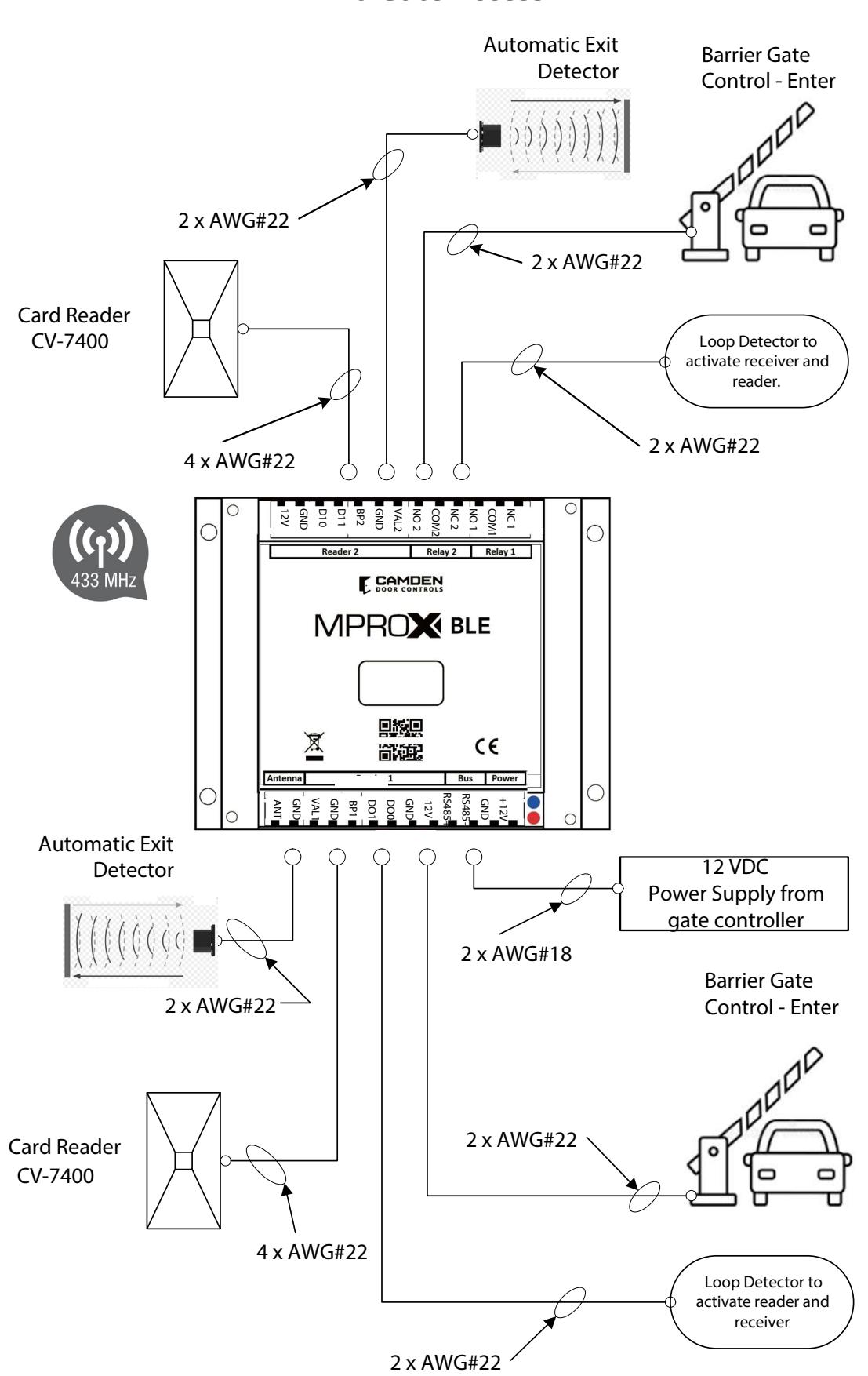
Two Gate Access
The system components consist of:
| Item | Description | Quantity | Camden Model # |
|---|---|---|---|
| 1 | Control module | 1 | CV-603 |
| 2 | Wiegand Card Reader | 2 | CV-7400 |
| 3 | Request to Exit detector | 2 | Provided by others |
| 4 | Loop detector | 2 | Provided by others |
| 5 | 12 VDC Power supply | 1 | Provided by gate controller board |
System Operation:
- a) The gate is normally closed.
- b) A user vehicle approaches the gate. The loop or beam detector validates the position of the vehicle is directly in front of the gate to activate the reader and receiver. Preventing the gate from being opened without the vehicle directly in front of it, will prevent unauthorized vehicles gaining entry.
- c) A user presents a card credential in front of the card reader. The card reader's red LED indicates it is powered. When the credential is within 2 inches, the reader will beep, and the controller red LED will pulse on 1 second to confirm the credential data was received. If the controller red LED blinks twice, the credential is being denied by the controller.
- d) If the credential is approved by the controller, the gate controller will trigger the gate to open. The gate controller will safely ensure the gate opens and closes with other sensors.
- e) Users exiting will be detected by the request to exit detector which will trigger the gate controller to open the gate.
- f) Administrators shall use the app to control and configure the CV-603 controller using wireless Bluetooth. A steady ON blue LED on the controller confirms there is a communication connection between the mobile device and the controller.
Two Gate Access
16. MULTIPLE CONTROLLERS WITH IDENTICAL CONFIGURATION AND USERS.
Cloning Controller Data Base
This application will enable controllers to be installed in multiple locations that share the same users and configuration.
During the SAVE ALL, all the controller data, users, badges, configuration are saved. The RESTORE ALL replaces all the controller data excluding the ADMIN password or the Equipment name.
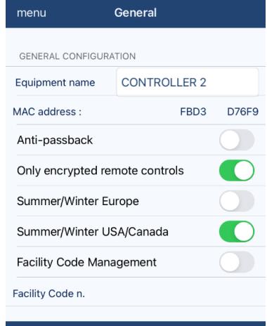
For example: To copy the data base from one controller to another, designate one as CONTROLLER 1 and the copied unit as CONTROLLER 2.
- 1) Label the equipment name as CONTROLLER 1 for CONTROLLER 1 and CONTROLLER 2 for CONTROLLER 2.
- 2) There may be 50 users, their groups and schedules on CONTROLLER 1.
- 3) Set the ADMIN password as cont1pwd on the CONTROLLER 1
- 4) Do a SAVE ALL and the App will create a FILE named "BACKUP CONTROLLER 1 2021 04 23 .txt" in your download folder (Android) or FILES (iOS). {file name format = BACKUP [Equipment Name] [Year] [Month] [Day]}.
- 5) Log onto CONTROLLER 2 and do a RESTORE ALL, all the existing data will be erased and replaced by CONTROLLER 1 backup data file except the ADMIN password and Equipment name
17. RESETTING CONTROLLER
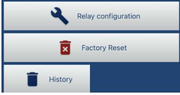
Contact technical support for instruction to erase the controller database including the passwords. A signed release letter will be requested.
18. COMPATIBLE PERIPHERALS
CV Series: System Readers, Cards & Tags
Camden supports MProx BLE and CV-350 access control system with an extensive line of readers and credential, for both indoor and outdoor use.
| LONG RANGE TRANSMITTER | |
|---|---|
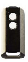
| CX-TXM-2 | Two button transmitter |
| CX-TXM2-B | Two button fob, package of 10 |
| HID/AWID DUAL FORMAT PROX READER | |
|---|---|
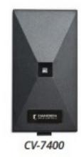
| CV-7400 | Narrow, compact, 4"-5" read range |
| CV-7820 | Single gang, 4"-5" read range |
| HID & AWID FORMAT CREDENTIALS | |||
|---|---|---|---|
| CV-CSA | AWID format prox. cards, clam shell style, package of 10 | ||
| CV-CSA-B | AWID format prox. cards, clam shell style, package of 100 | ||
| CV-ISA | AWID format ISO prox. cards, package of 10 | ||
| CV-ISA-B | AWID format ISO prox. cards, package of 100 | ||
| CV-KTA | AWID format ISO prox. key tag package of 25 | ||
| CV-CSH | HID format clam shell style card, package of 10 | ||
| CV-CSH-B | HID format clam shell style card, package of 100 | ||
| CV-ISH | HID format ISO prox card, package of 10 | ||
| CV-ISH-B | HID format ISO prox card, package of 25 | ||
| CV-KTH | HID format prox key tag, package of 25 | ||
| BLUETOOTH/ MIFARE DUAL FORMAT READER | |
|---|---|
| CV-7600 | BLE reader, up to 1 ft range |
| CV-7605 | BLE reader, up to 5 ft range |
| CV-7615 | BLE reader, up to 15 ft range |
| CV-7630 | BLE reader, up to 30 ft range |
| BLUETOOTH/ MIFARE FORMAT CREDENTIALS | ||
|---|---|---|
| CV-MBT | Smart phone BLE mobile credentials, package of 10 | |
| CV-MCS | MIRFARE clam shell cards, package of 10 | |
| CV-MKT | MIRFARE fob key, 2k memory, package of 10 | |
| CM-RQE70 | PIR REQUEST TO EXIT detector, white, w/ wiring harness, C/W (2) form C (DPDT) contacts, 12/24 VDC |
|---|---|
| CM-RQE70A | PIR REQUEST TO EXIT detector , white, w/ wiring terminal, C/W (2) form C (DPDT) contacts, 12/24 VDC |
| CM-RQE70BK | PIR REQUEST TO EXIT detector , black, w/ wiring harness, C/W (2) form C (DPDT) contacts, 12/24 VDC |
| CM-RQE70ABK | PIR REQUEST TO EXIT detector , black, w/ wiring terminal, C/W (2) form C (DPDT) contacts, 12/24 VDC |
| CM-RQEPW | Single gang adaptor plate (white) |
| CM-RQEPK | Single gang adaptor plate (black) |
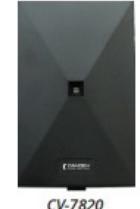


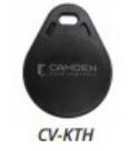
| CM-30C |
(13) English and French insert labels, 12V - 28V LED illuminated (red and green): 'Push to Exit',
'Exit', 'Occupied When Lit', bilingual versions and wheelchair symbol. |
| CM-30U |
(13) English and Spanish insert labels, 12V - 28V LED Illuminated (red and green): 'Push to Exit',
'Exit', 'Occupied When Lit' and wheelchair symbol. |
| CM-30E |
(1) English 'Push to Exit', 12-28V LED Illuminated. For French language 'Poussez Pour Ouvrir', order
CM-30F. Green, 'Push to Exit' |
| CM-30F | GREEN ILLUM "POUSSEZ POUR SORTIR" SW 12/24V LED |
| CM-xxx-DP | DPDT switch instead of SPDT switch |
| CM-331 |
Wired touchless switch, w/ built-in door control, 1 Relay, option for CM-TX99 wireless transmitter
and light ring |
| CM-324 | Wired touchless switch, economical, 1 Relay, no inputs, wireless or light ring |
| CM-325 | Wired 'Short Range' touchless switch, 1 Relay, no inputs, wireless or light ring |
| CM-332 |
Wired touchless switch, w/ built-in door control, 2 relays, option for CM-TX99 wireless transmitter
and light ring |
| CM-333 | Hybrid battery Powered Touchless Switch, 1 wired Relay, option for CM-TX99 wireless transmitter. |
| CM-330 | Battery Powered, Wireless Touchless Switch, w/ built-in Lazerpoint RF(tm) wireless transmitter. |
| CM-AF500 |
Single gang LED Illuminated annunicator labels include: 'Occupied When Lit', 'Locked When Lit'
(Green), 'Occupied/Occupe' (Red), 'Armed' (Red), 'Unlocked' (Green) |
| CM-AF501SO |
Single gang LED annunciator with adjustable sounder 'ASSISTANCE REQUESTED'. Add suffix 'F' for
French, suffix 'FE' for bilingual |
| CM-AF501SOF | Single gang LED annuancaitor with sounder, french |
| CM-AF501SOFE | Single Gang LED annunciator with sounder, english & french |
| CM-AF540SO |
Double gang, push/pull mushroom push button, red, 'Assistance Required', w/ LED annunciator
and adjustable sounder |
| CX-MDA | Magnetic contact, surface, SPST, white 15/16" (23mm) gap |
| CX-MDC | Magnetic contact, surface, SPDT, white 1" (25mm) gap |
| CX-MDH | Magnetic contact, recessed, SPST, white 1-1/16" (27mm) gap |
19. POWER:
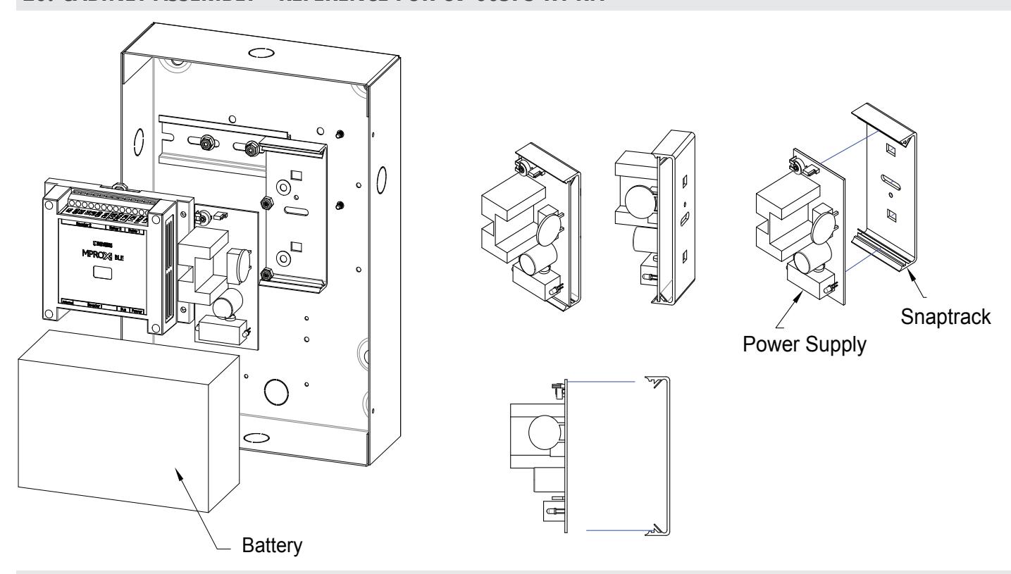
If you are using the Camden CV-603PS-K1 metal cabinet, the 12 VDC power supply is rated for 1.5 Amps without battery backup. Ensure all our devices are below this limit. Standby time of 24 hours @ 200mA with battery backup. The power supply provides 13.6 VDC power to charge a 4AH sealed lead-acid battery type. (Supplied by others.) The battery is protected with a PTC autoreset fuse.
Green LED: Remains on to confirm AC power is connected.
Red LED: Remains on to confirm DC power is being provided at the terminals.
Note: There is a 5-volt/12-volt jumper on the board. The factory has set it to 12 VDC.
20. CABINET ASSEMBLY - REFERENCE FOR CV-603PS-K1 KIT
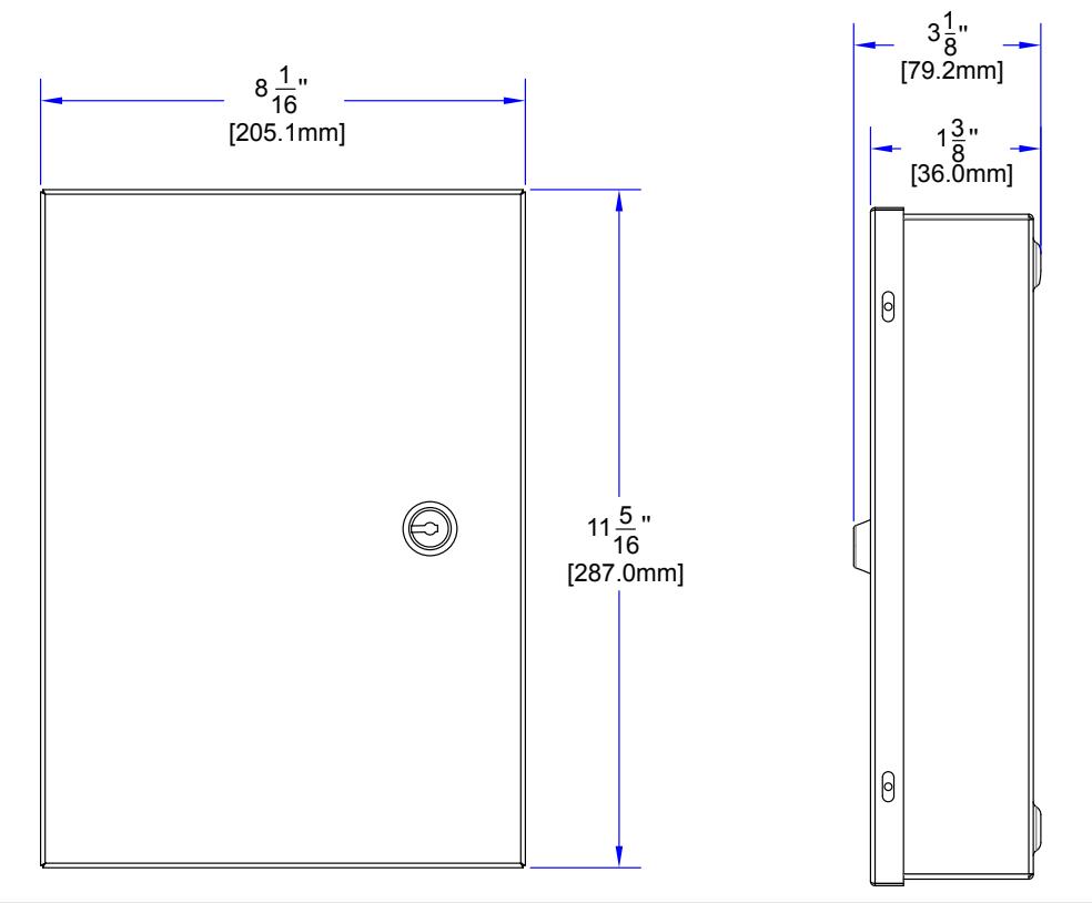
21. MECHANICAL DRAWING - FOR CV-603PS-K1 KIT CABINET

Call: 1.877.226.3369 / 905.366.3377
File: 40-82B269_CV-603-BLE_Reference_ Manual.indd Rev. February 03, 2023 Part No.: 40-82B269