BEST Electromechanical Locks W&M Series Catalog
Open the original PDF document
View PDF

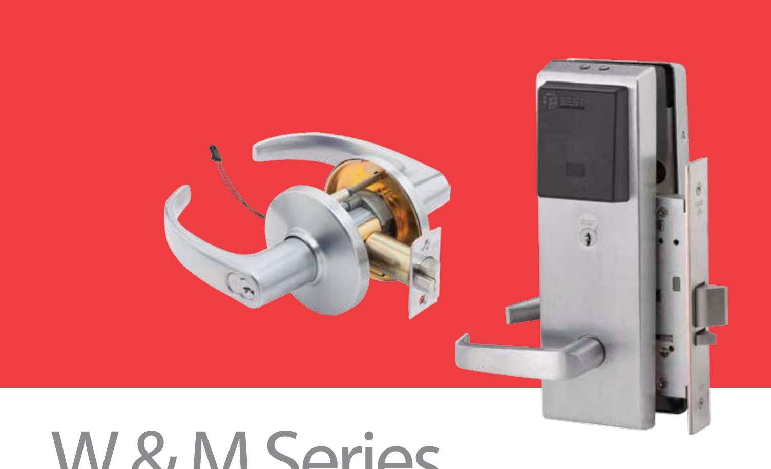
W & M Series
IDH MAX® & Electromechanical Locks
TABLE OF CONTENTS
| IDH MAX° introduction | |
|---|---|
| IDH MAX® features2 | 2-: |
| IDH Max ® and IDH Max ® 1300 comparison chart | |
| HM, KM, HW & KW options | |
| 40HM IDH MAX ® specifications, how-to-order | |
| 40HM IDH MAX° functions | |
| 93KM IDH MAX ® specifications, how-to-order | ( |
| Quick Connect, how-to-order7, | 20 |
| 93KM IDH MAX ® functions | |
| 40HW/8KW/9KW electrified lock introduction | |
| 40HW electrified specification | |
| 40HW electrified functions | 8-1 |
| 40HW electrified how-to-order |
|---|
| 8KW/9KW electrified specification1 |
| 8KW/9KW electrified how-to-order1 |
| 8KW/9KW electrified functions1 |
| Trim variations1 |
| Electrified accessories12,1 |
| Terminology1 |
| 1W electric switch lock introduction1 |
| Optional boxes1 |
| 1W electric switch lock how-to-order1 |
| 1W electric switch locks15-1 |
IDH MAX® – Introduction
The IDH MAX* from BEST offers convenience and efficiency for your electrified lock applications. Instead of installing reader devices, installing electrified strikes, installing door contacts and installing request-to-exit devices, you can now install the IDH MAX* in cylindrical or mortise lock applications. With IDH MAX* all of the formerly separate equipment needed to control access are self-contained in a single installation. The complexity of multiple wire runs is drastically reduced.
You can let BEST show you how to MAXimize your access control system with the IDH MAX*! For the name and location of your local office, visit our web site at www.bestaccess.com. IDH MAX* and W series locks are compatible with BEST's NT500, Mercury and most other Access Control Systems. The IDH Max* 1300 option will only work with the Mercury system and only on electrically unlocked "EU" functions.
IDH MAX® – Features
IDH Max® Features
Includes latch status, door status and request to exit features NOTE: Latch Status not available on Deadbolt functions
- The 1300 option eliminates the need for a PIM (Panel Interface Module)
- · Requires only one 4 conductor wire run
- Reduces number of components installed and visible at the door (PIR, RQE push buttons and door contacts)
- · Installation time is reduced
- The ROE switch senses the inside lever/knob rotation.
- All of the door components are housed in one manufacturer's hardware
- With the elimination of components, only the lockset is visible at the door
- The reader is integrated into the lockset escutcheon
- · Available in magnetic stripe and proximity readers
- · Available in all popular lever/knob styles and finishes
- · Operates with BEST interchangeable core as a mechanical override
- · Integrates with many manufacturer's on-line EAC equipment
Mortise Features
- Lock case meets the requirements as listed in the ANSI/BHMA A156.13 standard for Series 1000, Grade 1 Operational and Grade 2 Security locks
- UL listed for GYQS Electrically controlled single point locks or latches for use on 3 hr, A label doors (4' x 10'). The listing applies for both U.S. and Canadian applications
- · Door contact, request-to-exit, and latch status sensors positioned
inside lock case
- The door contact magnet is installed behind the strike and out of site (except when deadbolt option is ordered)
- All sensors are standard in IDH Max mortise locks
- The heavy duty design of the mortise lock results in less field maintenance and part failures
- Twist off lever spindle design protect internal lock parts from damage and failure.
- Oil impregnated stainless steel 3/4" anti-friction latchbolt reduces door closing force and wear.
Cylindrical Features
- · Non-handed levers allow for ease of installation
- Lock chassis meets the requirements as listed in the ANSI/BHMA A156.2, standard for Series 4000 Grade 1 locks
- UL listed for GYQS Electrically controlled single point licks or latches for use on 3 hr, A label single doors (4'x 10') GYJB. The listing applies for both U.S. and Canadian applications
- · Request-to-exit sensor positioned inside lock trim
- The ISC (Intelligent System Controller) is embedded behind the escutcheon secured and out of site
- Request-to-exit and door contact sensors are standard in IDH MAX cylindrical locks
Magnetic Stripe Electronic Lock Features
- Durable material has teflon-like characteristics for increased life and wear resistance
- Variable read rate allows for easy usage

Proximity Card Reader Features
- · HID and Motorola/Indala proximity cards supported
- Usable in most environmental/exterior applications.
1300 Option Features
• Eliminates need for small panel interface module
- Eliminates reader interface board
- Incorporates 3 modules into a single electronics board inside IDH Max escutcheon trim
- Connects directly to ACP via 2 wire RS485 connection
IDH MAX<sup>®</sup> & IDH MAX<sup>®</sup> 1300 Comparison Chart
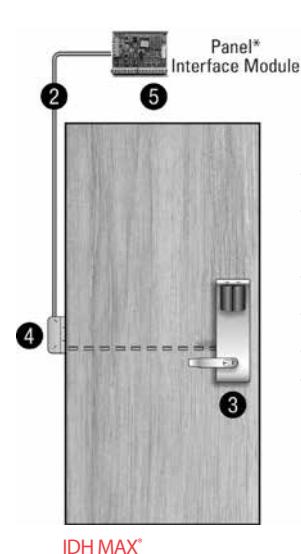
IDH MAX°
- Prep door for IDH MAX°
- Run single 4 conductor wire for IDH MAX°
- Install IDH MAX®
- Install electrified hinge
- Mount PIM
- * Operates with most control panel hardware, Mercury control panels.
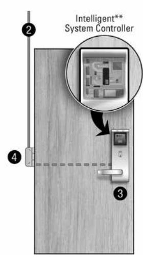
IDH MAX° 1300
IDH MAX° 1300
- Prep door for IDH MAX°
- Run single 4 conductor wire for IDH MAX° 1300
- Install IDH MAX<sup>®</sup> 1300 which includes Intelligent System
- · Install electrified hinge
- ** Operates with Mercury control panels only.
HM, KM, HW & KW - Options
AL – Besides complying with a wide variety of accessibility codes and ordinances, lever handles are available with a special abrasive feature. Abrasive strip on the lever immediately identifies warnings on doors to hazardous areas for the blind.
BRK – When excessive force (approx. 300 inch lbs.) is applied to #4, #6 keyed knobs, they "breakaway" and spin freely, thus allowing entrance only by key. Simple part replacement returns lock to functional usage.
C – The easy to use quick connect system enables efficient installation to the respective BEST Lock electrical options ordered.
IDH – The Integrated Door Hardware groups three components into one hardware package. 1. Door status switch (normally closed) 2. Request-to-Exit switch (normally open) 3. Electrically controlled locking mechanism.
KNL – Knurl feature is available only on #6 knobs. The knurling is machined into the outer edge of the knob. The knurled feature can be used for blind, safety, or accessibility applications.
LL – Lead lined feature can be used to protect against X-rays. Since the majority of lead lined doors contain the lead in the surface of the door, the knob lockset provide lead lining for the holes cut in the door when preparing the door for the trim.
LM – The Lost Motion feature allows the lever handle to turn freely when it is locked without retracting the latchbolt assembly. This feature makes over-torque abuse more difficult to achieve.
SH – Security head provided for all exposed screws.
RQE – Cylindrical or Mortise locksets can be supplied with a request-to-exit switch. A normally open switch provides momentary switch closure when the inside lever/knob is rotated.
TAC – Grooves are machined into knobs to improve grip or to be used as a warning in hazardous areas. This option can be used for blind, safety or accessibility applications.
Thick door – Specify thickness if other than 1 3/4".
TL – Tactile levers may be used in areas where improved grip is required or as a warning in hazardous or Safety First areas. Grooves are machined into the back of the hand grasp portion of the lever to improve grip and/or provide a sensory warning. This option can be used for blind, safety, or accessibility applications.
1300 – Integrated BAS1300/LNL1300 reader electronics board or (ISC) Intelligent System Controller is embedded behind the escutcheon secured and out of site. Functions with Mercury on-line equipment only.
NOTE: 1300 option not available on any "EL" electrically locked functions.
40HM IDH Max® – Specifications
Mechanical
Case – Heavy wrought steel, 5 7⁄8" H x 4 1⁄4" D x 1" W steel parts are zinc dichromate plated for corrosion protection.
Faceplate – Brass or bronze, 8" H x 1 1⁄4" W x 1/16" T . Lock face automatically adjusts to proper bevel during installation.
Strike – Brass, bronze or stainless steel base material, 4 7⁄8" H x 1 1⁄4" W x 3⁄32" T. Fits standard
door frame cut out as specified in ANSI A115.1. Universal (non-handed) strike supplied standard with lock.
Backset – 2 3/4"
Door thickness – For doors 1 3⁄4" – 3" thick. (specify thickness when ordering)
Installation – Lock requires modified door prep to mount the trim. Faceplate dimensions fit standard door preparation as specified in ANSI A115.1,. Lockset is easily reversible to match door handing without opening the mortise case.
Latchbolt – Solid stainless steel, 3/4" throw. Latch is oil-impregnated for anti-friction operation. Reversible without opening case.
Deadbolt – Solid stainless steel, 1" throw.
Auxiliary bolt – Stainless steel, non-handed.
Escutcheons – 10 1/2" H x 3 5/16" W x 1" D (1" at the top, sloping down to 3/4" at the bottom)
Knobs – Diameter: 2 1⁄8" Projection on door: 2 7⁄8" #4, #6 knobs: Material machined from brass or bronze.
Lever handle – Brass, bronze or stainless steel. (Lever #3, #14 and #15 conform to California Titles 19 and 24.)
Mounting – Knob and lever attached with hardened set screw on inside knob or inside lever.
Finish –
- 605-bright brass, clear coated
- 612-satin bronze, clear coated
- 625-bright chromium plated
- 630-satin stainless steel
45HM IDH MAX® Mortise
- 606-satin brass, clear coated
- 613-oxidized satin bronze, oil
- 626*-satin chromium plated
- 690**-dark bronze.
- 611-bright bronze, clear coated
- rubbed
- 629-bright stainless steel
- * 613 finish is designed to wear over time, providing an "antique" appearance. ** 690 finish will continue as a dark brown appearance over time.
Antimicrobial Finishes –
- 626AM Satin Chrome Plated with UltraShield Antimicrobial coating
- 630AM Satin Stainless Steel with UltraShield Antimicrobial coating
Electronic
Maximum current draw: 1.1 Amp for 50 milliseconds. Typical current draw (hold condition): 650 milliAmps Voltage: 10.2 to 13.2 V (DC only) Magnetic Stripe Card Reader
Read Rate – 5 inches per second to 50 inches per second.
Card Thickness – ISO standard .030" ± .003 thick. Compliance to FCC, Canadian, and European EMC requirements; for interference FCC Class A digital apparatus.
Proximity Reader – ANSI/BHMA A156.25 compliant. Compatible with Motorola / Indala and HID proximity cards. ABA and Wiegand output. Weatherproof bezel and gasket provide protection for outdoor use. (Usable in most environmental/exterior applications)
Card Read Range – 0 – 3 inches. Compliance to US FCC, Canadian FCC, and European EMC requirements
ESD Protection – 15 Kilo Volt
40HM IDH MAX® – How To Order
| 45HM | 7 | DEU | 14 | MS | 626 | RH | KNL |
|---|---|---|---|---|---|---|---|
| Series |
Core
Housing |
Function |
Lever/Knob
Style |
Trim Style * | Finishes | Handing | Options |
|
45HM–
IDH Max™ Mortise |
0– Keyless or
less cylinder, 7– 7 pin IC housing accepts all BEST cores |
DEL– single key latch, fail safe
DEU– single key latch, fail secure NXEL– keyless, latch, fail safe NXEU– keyless, latch, fail secure TDEL– single key deadbolt, fail safe TDEU– single key deadbolt, fail secure LEL– keyless, deadbolt, fail safe LEU– keyless, deadbolt, fail secure |
Levers
14– curved return 15– curved angle return 16– curved no return 17– gullwing no return Knobs 4– round |
MS–magnetic
stripe PM–proximity Motorola PH– proximity HID MSA– other cylinder PHA– other cylinder PMA– other cylinder |
605 606 611 612
613 618 619 625 626 690 Antimicrobial Finishes 626AM – Satin Chrome Plated with UltraShield Antimicrobial coating 630AM – Satin Stainless Steel with UltraShield Antimicrobial coating |
RH
RHRB LH LHRB |
C – quick connect
SH – security head screws TAC – tactile lever Thick Door – specify thickness if other than 1 3/4" 7/8" LTC– flat lip strike 1300** – Mercury direct connect |
| (page 5) | (page 11) | (page 11) |
* Standard readers use BEST concealed cylinder; Adaptation trim can accept other manufacturers cylinders.
**1300 option not available on any "EL" electrically locked functions.

40HM IDH Max® – Functions
| Function | Latch | Outside Knob/Lever | Inside Knob/Lever | |||
|---|---|---|---|---|---|---|
| Operated by | Locked by | Unlocked by | Locked by | Unlocked by | ||
|
DEL–Locked
Fail Safe |
• Outside knob/lever when power is
removed from the solenoid • Outside key • Inside knob/lever Latchbolt is deadlocked by an auxiliary latch |
Applying power to the
solenoid; remains locked while power is on. |
Removing power from the solenoid | Cannot be locked | Always unlocked | |
| Powered by 12V DC. temperature control module is not needed. | ||||||
|
DEU–Unlocked
Fail Secure |
• Outside knob/lever when power is
applied from the solenoid • Outside key • Inside knob/lever Latchbolt is deadlocked by an auxiliary latch |
Removing power from the
solenoid |
Applying power to the solenoid; remains
unlocked while power is on. |
Cannot be locked | Always unlocked | |
| Powered by 12V DC. temperature control module is not needed. | ||||||
|
NXEL–Locked
Fail Safe |
• Outside knob/lever when power is
removed from the solenoid • Outside key • Inside knob/lever Latchbolt is deadlocked by an auxiliary latch |
Applying power to the
solenoid; remains locked while power is on. |
Removing power from the solenoid | Cannot be locked | Always unlocked | |
| Powered by 12V DC. temperature control module is not needed. | ||||||
|
NXEU–Unlocked
Fail Secure |
• Outside knob/lever when power is
applied from the solenoid • Outside key • Inside knob/lever Latchbolt is deadlocked by an auxiliary latch |
Removing power from the
solenoid |
Applying power to the solenoid; remains
unlocked while power is on. |
Cannot be locked | Always unlocked | |
| Powered by 12V DC. temperature control module is not needed. | ||||||
|
TDEL–Locked
Fail Safe |
• Outside key
• Outside knob/lever when power is removed from the solenoid. • Inside knob/lever Latchbolt is deadlocked by an auxiliary latch |
Applying power to the
solenoid; remains locked while power is on. Deadbolt operated by: • Outside key • Inside thumb turn |
Removing power from the solenoid
Deadbolt and Latchbolt retracted simultaneously by: • Inside knob/lever • Outside knob/lever when power is removed |
Cannot be locked | Always unlocked | |
| Powered by 12V DC. temperature control module is not needed. | ||||||
|
TDEU–Unlocked
Fail Secure |
• Outside knob/lever when power is
applied from the solenoid • Outside key • Inside knob/lever Latchbolt is deadlocked by an auxiliary latch |
Removing power from the
solenoid Deadbolt operated by: • Outside key • Inside thumb turn |
Applying power to the solenoid; remains
unlocked while power is on. Deadbolt and Latchbolt retracted simultaneously by: • Inside knob/lever • Outside knob/lever when power is applied |
Cannot be locked | Always unlocked | |
| Powered by 12V DC. temperature control module is not needed. | ||||||
|
LEL–Locked
Fail Safe |
• Outside knob/lever when power is
removed from the solenoid • Inside knob/lever Latchbolt is deadlocked by an auxiliary latch |
Applying power to the
solenoid; remains locked while power is on. Deadbolt extended by: Inside thumb turn |
Removing power from the solenoid
Deadbolt retracted by: • Inside thumb turn • Inside knob/lever retracts the deadbolt and latchbolt simultaneously • Outside lever when power is removed |
Cannot be locked | Always unlocked | |
| Powered by 12V DC. temperature control module is not needed. | ||||||
|
LEU–Unlocked
Fail Secure |
• Outside knob/lever when power is
removed from the solenoid • Outside key • Inside knob/lever Latchbolt is deadlocked by an auxiliary latch |
Removing power from the
solenoid Deadbolt extended by: Inside thumb turn |
Applying power to the solenoid; remains
locked while power is on. Deadbolt retracted by: • Inside thumb turn • Inside knob/lever retracts the deadbolt and latchbolt simultaneously • Outside knob/lever when power is applied |
Cannot be locked | Always unlocked | |
| Powered by 12V DC. temperature control module is not needed. | ||||||
Shading indicates a ridged lever/knob in a non-energized state.
9KM IDH MAX® – Specifications
Mechanical
Materials – Internal parts are brass, zinc or corrosion-treated steel.
Chassis – 2 1⁄16" diameter to fit 2 1⁄8" diameter hole in door.
Strike – Brass, bronze, or stainless steel base material; STK 2 3/4" H standard, S3 4 7/8" H.
Fits standard door frame cut out as specified in ANSI A115.1. Strike box supplied as standard.
Backset – 2 3⁄4" standard, 3 3⁄4" and 5" available.
Door Thickness – Standard lock configuration designed for doors 1 3/4" – 2 1/4" thick.
Installation – Lock dimensions requires modified door prep ANSI A156.2 Series 4000, Grade 1 to mount housing.
Latchbolt – 9⁄16" throw.
Escutcheons – 10 1/2" H x 3 5/16" W x 1" D (1" at the top, sloping down to 3/4" at the bottom).
Knobs – Diameter: 2 1⁄8" Projection on door: 2 7⁄8" #4, #6 knobs: Material machined from brass or bronze.
Lever handle – Made from high-quality zinc alloy. Body is approximately 1 5⁄8" in diameter: Handle is approximately 4 3⁄4" in length (from center-line of chassis). Lever styles 14 and 15 return to a minimum of 1/2" of door surface. Lever 16 does not return.
Finish –
- 605-bright brass, clear coated
- 612-satin bronze, clear coated
- 626-satin chromium plated
9KM IDH MAX® Cylindrical
- 606-satin brass, clear coated
- 613*-oxidized satin bronze, oil rubbed
- 690**-dark bronze
- 611-bright bronze, clear coated
- 625-bright chromium plated
- * 613 finish is designed to wear over time, providing an "antique" appearance. ** 690 finish will continue as a dark brown appearance over time.
Antimicrobial Finishes –
- 626AM Satin Chrome Plated with UltraShield Antimicrobial coating
- 630AM Satin Stainless Steel with UltraShield Antimicrobial coating
Electronic
Maximum Current Draw – 850 MilliAmps, for 50 milliseconds
Typical Current Draw (hold condition) – 550 milliAmps
Voltage – 10.2 to 13.2 V (DC only)
Magnetic Stripe Card Reader:
Read Rate – 5 inches per second to 50 inches per second.
Card Thickness – ISO standard .030" ± .003 thick. Compliance to FCC, Canadian, and European EMC requirements; for interference FCC Class A digital apparatus.
Proximity Reader – ANSI/BHMA A156.25 compliant, Compatible with Motorola / Indala and HID proximity cards, ABA and Wiegand output Weatherproof bezel and gasket provide protection for outdoor use. (Usable in most environmental/exterior applications).
Card Read Range – 0 – 3 inches. Compliance to US FCC, Canadian FCC, and European EMC requirements
ESD Protection – 15 Kilo Volt
9KM/8KM IDH MAX® – How To Order
| 9KM3 | 7 | DDEU | 14 | MS | STK | 626 | TL |
|---|---|---|---|---|---|---|---|
|
Series
Backset |
Core
Housing |
Function |
Lever/Knob
Style |
Trim
Style |
Strike
Package |
Finishes** | Options* |
|
Lever
9KM3– 2 3/4" 9KM4– 3 3/4" 9KM5– 5" Knob 8KM3– 2 3/4" 8KM4– 3 3/4" 8KM5– 5" |
0– keyless
7– 7 pin housing accepts all BEST® cores |
DDEU–
electrically unlocked DDEL– electrically locked |
Levers
14– curved return 15– curved angle return 16– curved no return Knobs 4– round 6– tulip |
MS–magnetic
stripe PM– proximity Motorola PH– proximity HID |
STK– 2 3/4"
ANSI S3– 4 7/8" ANSI |
605 606 611 612
613 618 619 625 626 690 Antimicrobial Finishes 626AM – Satin Chrome Plated with UltraShield Antimicrobial coating 630AM – Satin Stainless Steel with UltraShield Antimicrobial coating |
8KM:
BRK – breakaway knob, KNL – knurled knob, TAC – tactile knob 9KM: AL – abrasive lever, LM – lost motion, TL – tactile lever Note: specify inside (I), outside (O), or both (B) for AL, TL,TAC, KNL options Both 8KM & 9KM: C – quick connect, SH – security head screws 3/4 – 3/4" throw latch 1300 – Mercury direct connect *** |
| (page 7) | (page 11) | (page 11) | (page 3) |
* Please reference the BEST price list for a complete list of options. ** Handles and trim are made from a zinc alloy, and have been plated to be equivalent in appearance to the finishes listed. *** 1300 option not available on any "EL" electrically locked functions.


Cylindrical Lock – Functions
| Function | Latch | Outside Knob/Lever | Inside Knob/Lever | |||
|---|---|---|---|---|---|---|
| Operated by | Locked by | Unlocked by | Locked by | Unlocked by | ||
| DDEL–Locked |
• Rotating the inside knob/lever,
• Rotating the outside knob/lever– only when power is off, • Turning the key in the outside knob/lever. Latchbolt is deadlocked |
Applying power to the
solenoid; remains locked while power is on. |
Removing power from
the solenoid |
Cannot be locked | Always unlocked | |
| Powered by 12V DC. Temperature control module (TCM) is not needed. | ||||||
| DDEU–Unlocked |
• Rotating the inside knob/lever,
• Rotating the outside knob/lever– only when power is on, • Turning the key in the outside knob/lever. Latchbolt is deadlocked |
Removing power from the
solenoid |
Applying power to
the solenoid; remains unlocked while power is on. |
Cannot be locked | Always unlocked | |
| Powered by 12V DC. Temperature control module (TCM) is not needed. | ||||||
Shading indicates a ridged lever/knob in a non-energized state.
40HW/8KW/9KW Electrified Lock Introduction
The 40HW, 8KW, and 9KW electromechanical locks provide fail-safe (electrically locked) and fail-secure (electrically unlocked) operation. They also provide a way to lock and unlock the door from a remote location for safety, security, or convenience through an individual switch, switch lock, relay, access control system, or other automatic control system. More importantly, these locks exhibit the same features and meet the same standards and specifications as our mechanical 40H mortise and 8K/9K heavy duty cylindrical locksets.
How To Order BEST Quick Connect Pre-Wired Plug-In Connectors
To order the BEST Quick Connect pre-wired plug-in connectors, include the "C" suffix for the BEST Locks. See page 20 for more details on how the BEST Quick Connect systems works.
Example: BEST Locks 45HW 7 DEL 14H 626 RH DSC
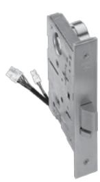
BEST Locks 9KW 37 DEU 15CS TK 626 24 VC
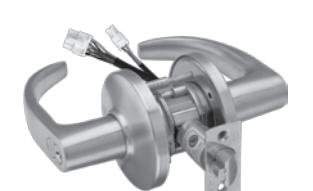
40HW Electrified – Specifications
Types:
- 12 volts AC or DC 0.60 amps
- 24 volts AC or DC 0.45 amps
- All EU functions: Electrically Unlocked (Fail Secure)
- All EL functions: Electrically Locked (Fail Safe)
Approval Listings:
- UL listed for GYQS Electrically-controlled singlepoint locks or latches.
- This product has been approved by the California State Fire Marshal (CSFM) pursuant to section 13144.1 of the California Health and Safety Code.
- Approved by the city of New York Board of Standards and Appeals under calendar number 49-88-SA. See CSFM listing No. 4136-1175:101 for allowable values and/or conditions for use concerning material presented in this document. It is subject to re-examination, revisions and possible cancellation.
NOTE: All w-series locks require the use of a (TCM) Temperature Control Module. TCM and TCM connector are supplied standard with every order.
40HW Electrified – How To Order
| 45HW | 7 | NXEU | 12 | J | 612 | LH | RQE |
|---|---|---|---|---|---|---|---|
| Series |
Core Hous
ing |
Function |
Lever
Style |
Trim
Style |
Finishes | Handing | Options |
|
45HW– lever
47HW– lever high security |
45HW:
0– keyless or less cylinder, 7– 7 pin IC housing accepts all BEST cores 47HW: 7– 7 pin (accepts 5C cores only) |
45HW/47HW:
DEL–single key latch, fail safe DEU– single key latch, fail secure WEL– double key latch, fail safe WEU– double key latch, fail secure TDEL–single key deadbolt, fail safe TDEU–single key deadbolt, fail secure TWEL–double key deadbolt, fail safe TWEU–double key deadbolt, fail secure 45HW only: NXEL–keyless, latch, fail safe NXEU–keyless, latch, fail secure LEL– keyless, deadbolt, fail safe LEU– keyless, deadbolt, fail secure |
Levers:
3– solid tube/return 12– solid tube/no return 14– curved return 15– contour/angle return 16– curved/no return 17– gullwing no return Knobs: 4– round |
45HW:
H– 2 3/4" flat J– wrought M– forged N– forged concealed cylinder* S– 3 1/2" flat R– 2 3/4" concave 47HW: M– forged |
45HW:
605 606 611 612 613 618 619 625 626 630 690 47HW: 626 630 |
RH
RHRB LH LHRB |
AL – abrasive lever
C – quick connect LL – lead lined LS – latch status DS – door status RQE – request to exit SH – security head screws TL – tactile lever Thick Door – specify thickness if other than 1 3/4" (1 3/4" min x 4" max) 12V–Specify 12 Volt System (standard lock voltage is 24V) |
| (pages 8–9) | (page 11) | (page 11) | (page 3) |
* & quot;N" trim not available on double keyed functions.
40HW Electrified – Functions
| Function |
Latch
Outside Knob/Lever |
Inside Knob/Lever | ||||||
|---|---|---|---|---|---|---|---|---|
| Operated by | Locked by | Unlocked by | Locked by | Unlocked by | ||||
|
DEL–Locked
Fail Safe |
• Outside knob/lever when
power is removed from the solenoid • Outside key • Inside knob/lever Latchbolt is deadlocked by an auxiliary latch |
Applying power to solenoid;
remains locked while power is on |
Removing power from solenoid | Cannot be locked | Always unlocked | |||
| Powered by 12 or 24 volts AC/DC & 0.60 or 0.45 amps, continuous duty. Temperature control module (TCM) included. | ||||||||
|
DEU–Unlocked
Fail Secure |
• Outside knob/lever when
power is applied to the solenoid • Outside key • Inside knob/lever Latchbolt is deadlocked by an auxiliary latch |
Removing power from solenoid Applying power to solenoid; remains
unlocked while power is on |
Cannot be locked | Always unlocked | ||||
| Powered by 12 or 24 volts AC/DC & 0.60 or 0.45 amps, continuous duty. Temperature control module (TCM) included. | ||||||||
|
WEL–Locked
Fail Safe |
• Inside and Outside knob/lever
when power is removed from the solenoid • Inside/Outside key Latchbolt is deadlocked by an auxiliary latch |
Applying power to solenoid;
remains locked while power is on |
Removing power from solenoid |
Applying power to
the solenoid; remains locked while power is on |
Removing power
from the solenoid |
|||
| Temperature control module (TCM) included. | ||||||||
| Powered by 12 or 24 volts AC/DC & 0.60 or 0.45 amps, continuous duty. Applying voltage locks inside & outside knobs/levers simultaneously. | ||||||||
|
WEU–Unlocked
Fail Secure |
• Inside and Outside knob/lever
when power is applied to the solenoid • Inside/Outside key Latchbolt is deadlocked by an auxiliary latch |
Removing power from
solenoid |
Applying power to solenoid; remains
unlocked while power is on |
Removing power
from solenoid |
Applying power to
solenoid; remains unlocked while power is on |
|||
| control module (TCM) included. | Powered by 12 or 24 volts AC/DC & 0.60 or 0.45 amps, continuous duty. Removing voltage locks inside & outside knobs/levers simultaneously. Temperature | |||||||
|
TDEL–Locked
Fail Safe |
• Outside key
• Outside knob/lever when power is removed from the solenoid Latchbolt is deadlocked by an auxiliary latch |
Applying power to solenoid;
remains locked while power is on Deadbolt operated by: • Outside key • Inside thumb turn |
Removing power from solenoid
Deadbolt and latchbolt retracted simultaneously by: • Inside knob/lever • Outside knob/lever when power is removed. |
Cannot be locked | Always unlocked | |||

40HW Electrified – Functions (Continued)
|
TDEU–Unlocked
Fail Secure TWEL–Locked Fail Safe |
Operated by
• Outside key • Outside knob/lever when power is applied to the solenoid Latchbolt is deadlocked by an auxiliary latch • Outside & inside key • Outside & Inside knob/ lever when power is removed from the solenoid Latchbolt is deadlocked by an |
Locked by
Removing power from solenoid Deadbolt operated by: • Outside key • Inside thumb turn Applying power to solenoid; remains locked while power is on |
Unlocked by
Applying power to solenoid; remains unlocked while power is on Deadbolt and latchbolt retracted simultaneously by: • Inside knob/lever • Outside knob/lever when power is applied. Powered by 12 or 24 volts AC/DC & 0.60 or 0.45 amps, continuous duty. Temperature control module (TCM) included. Removing power from solenoid |
Locked by
Cannot be locked |
Unlocked by
Always unlocked |
|||
|---|---|---|---|---|---|---|---|---|
| auxiliary latch |
Deadbolt operated by:
• Outside or inside key • Outside & Inside knob/lever when power is removed from |
Applying power to
solenoid; remains locked while power is on |
Removing power
from solenoid |
|||||
| the solenoid | Temperature control module (TCM) included. | |||||||
| Powered by 12 or 24 volts AC/DC & 0.60 or 0.45 amps, continuous duty. Applying voltage locks inside & outside knobs/levers simultaneously. | ||||||||
|
TWEU–Unlocked
Fail Secure |
• Outside & inside key
• Outside & Inside knob/lever when power is applied to the solenoid Latchbolt is deadlocked by an |
Removing power from solenoid
Deadbolt operated by: • Outside or inside key • Outside & Inside knob/lever when power is applied to the |
Applying power to solenoid; remains
unlocked while power is on |
Removing power
from solenoid |
Applying power to
solenoid; remains unlocked while power is on |
|||
| auxiliary latch | solenoid | Temperature control module (TCM) included. | ||||||
| Powered by 12 or 24 volts AC/DC & 0.60 or 0.45 amps, continuous duty. Removing voltage locks inside & outside knobs/levers simultaneously. | ||||||||
|
NXEL–Locked
Fail Safe |
• Outside knob/lever when
power is applied to the solenoid • Inside knob/lever Latchbolt is deadlocked by an |
Applying power to
solenoid; remains locked while power is on |
Removing power from solenoid | Cannot be locked | Always unlocked | |||
| auxiliary latch | Temperature control module (TCM) included. | |||||||
| Powered by 12 or 24 volts AC/DC & 0.60 or 0.45 amps, continuous duty. Temperature control module (TCM) included. | ||||||||
|
NXEU–Unlocked
Fail Secure |
• Outside knob/lever when
power is applied to the solenoid • Inside knob/lever Latchbolt is deadlocked by an auxiliary latch |
Removing power from solenoid |
Applying power to solenoid; remains
unlocked while power is on |
Cannot be locked | Always unlocked | |||
| Powered by 12 or 24 volts AC/DC & 0.60 or 0.45 amps, continuous duty. Temperature control module (TCM) included. | ||||||||
|
LEL–Locked
Fail Safe |
• Outside knob/lever when
power is removed from the solenoid • Inside knob/lever Latchbolt is deadlocked by an auxiliary latch |
Applying power to the
solenoid; remains locked while power is on Deadbolt extended by: Inside thumb turn |
Removing power from the solenoid
Deadbolt retracted by: • Inside thumb turn • Inside knob/lever retracts the deadbolt and latchbolt simultaneously • Outside knob/lever when power is |
Cannot be locked | Always unlocked | |||
| removed | ||||||||
| LEU–Unlocked | • Outside knob/lever when | Removing power from the |
Powered by 12 or 24 volts AC/DC & 0.60 or 0.45 amps, continuous duty. Temperature control module (TCM) included.
Applying power to the solenoid; |
Cannot be locked | Always unlocked | |||
| Fail Secure |
power is applied to the
solenoid |
solenoid
Deadbolt extended by: Inside |
remains unlocked while power is on
Deadbolt retracted by: |
|||||
|
• Inside knob/lever
Latchbolt is deadlocked by an auxiliary latch |
thumb turn |
• Inside thumb turn
• Inside knob/lever retracts the deadbolt and latchbolt simultaneously • Outside knob/lever when power is |
||||||
|
applied
Powered by 12 or 24 volts AC/DC & 0.60 or 0.45 amps, continuous duty. Temperature control module (TCM) included. |
||||||||
ATTENTION: Locksets that secure both sides of the door are controlled by building codes and the Life Safety Code® In an emergency exit situation, failure to quickly unlock the inside lever could be hazardous or even fatal.
8KW & 9KW Electrified Locks – Specifications
Types:
- 12 volts AC/DC when used with supplied TCM 0.50 amps
- 24 volts AC/DC when used with supplied TCM 0.18 amps
- All EU functions: Electrically Unlocked (Fail Secure)
- All EL functions: Electrically Locked (Fail Safe)
Approval Listings:
- UL listed for GYQS Electrically-controlled singlepoint locks or latches.
- This product has been approved by the California State Fire Marshal (CSFM) pursuant to section 13144.1 of the California Health and Safety Code.
- Approved by the city of New York Board of Standards and Appeals under calendar number 730-89-SA. See CSFM listing No. 4136-1175:103. It is subject to re-examination, revision and possible cancellation.
Door thickness:
• Standard lock configuration designed for doors 1 3/4" – 2 1/4" thick.
NOTE: All W-series locks require the use of a (TCM) Temperature Control Module. A TCM and TCM connector are supplied standard with every order.
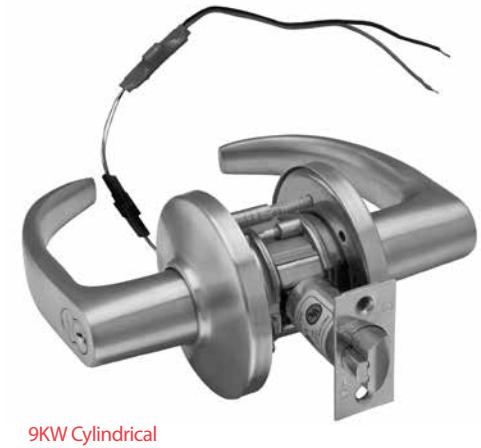
Electrically-Operated Lockset
8KW & 9KW Electrified Locks – How To Order
| 9KW3 | 7 | DEU | 14 | K | STK | 626 | TL |
|---|---|---|---|---|---|---|---|
| Series |
Core
Housing |
Function |
Lever
Style |
Trim
Style |
Srike
Package |
Finishes* | Options |
|
8KW:
8KW3– 2 3/4" 8KW4– 3 3/4" 8KW5– 5" 9KW: 9KW3– 2 3/4" 9KW4– 3 3/4" 9KW5– 5" |
0– keyless
7– 7 pin housing accepts all BEST® cores |
DEU–
electrically unlocked DEL–electrically locked |
8KW:
4–round 6–tulip 9KW: 14– curved return 15– contour angle return 16– curved no return |
C– 3" convex
D– 3 1/2" convex K– 3" convex –no ring L– 3 1/2" convex –no ring |
STK –
2 3/4" ANSI S3 – 4 7/8"ANSI |
605 606
611 612 613 618 619 625 626 690 |
8KW only:
BRK– breakaway knob KNL– knurled knob TAC– tactile knob 9KW only: AL– abrasive lever LM– lost motion RQE– request-to-exit TL– tactile lever Note: specify inside (I), outside (O), or both (B) for AL, TL, TAC, KNL options 8KW & 9KW: C – quick connect LL– lead lined SH– security head screws 3/4– 3/4" throw latch 12V– Specify 12 Volt System (standard lock voltage is 24V) |
| (See Below) | (page 11) | (page 11) | (page 3) |
* Handles are made from a zinc alloy, and have been plated to be equivalent in appearance to the finishes listed.
8KW & 9KW Electrified Locks – Functions
| Function | Latch | Outside Knob/Lever | Inside Knob/Lever | ||||||
|---|---|---|---|---|---|---|---|---|---|
| Operated by | Locked by | Unlocked by | Locked by | Unlocked by | |||||
| DEL-Locked |
• Rotating the inside
knob/lever • Rotating the outside knob/lever—only when power is off |
Applying power to the
solenoid; remains locked while power is on. |
Removing power from
the solenoid |
Cannot be locked | Always unlocked | ||||
| • Turning the key in the outside knob/lever. | |||||||||
| DEU-Unlocked |
Locks are powered by 12 or 24 volts AC/DC at 0.50 amps or 0.18 amps. Temperature control module (TCM) included
• Rotating the inside knob/lever, Removing power from the Applying power to the Cannot be locked Always unlocked solenoid solenoid; remains • Rotating the outside knob/lever—only unlocked while power when power is on, is on. |
||||||||
|
•Turning the key in the outside knob/lever.
Locks are powered by 12 or 24 volts AC/DC at 0.50 amps. or 0.18 amps. Temperature control module (TCM) included |
|||||||||
Shading indicates a ridged lever/ knob in a non-energized state.

Knob Styles
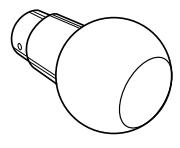
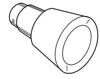
#4 knob #6 knob
Lever Styles
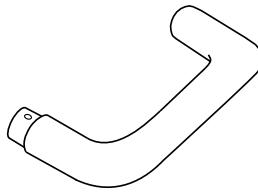

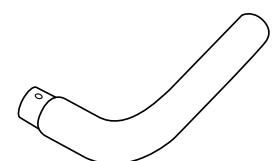
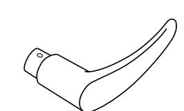
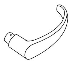

Mortise Rose Trims
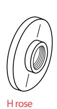
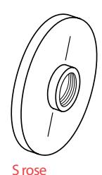
Cylindrical Rose Trims
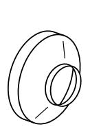

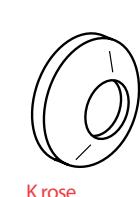
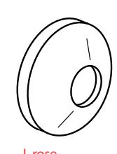
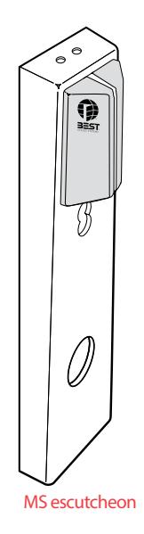
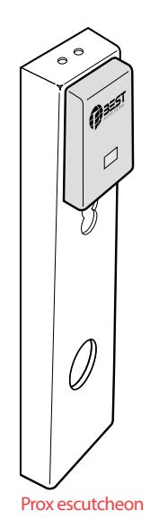
Escutcheon Trim Variations
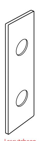
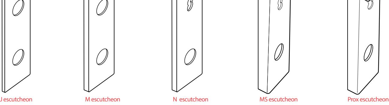
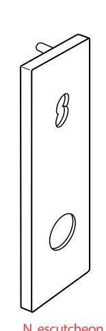
ELECTRIFIED ACCESSORIES
8W599 Features:
- Offers exceptionally high power for its compact size
- UL listed
- Thermally fused
- Convenient 4 point mounting provision allows rapid installation in a standard 1/2" knockout
Specifications:
Primary voltage – 120 VAC (Wire Leads)
Secondary voltage – 124 VAC (Screw Terminals)
Secondary VA – 140 volts-amperes
Dimensions – 12 1/4" x 2 1/8" x 2 15/16"
To order specify: 18W599
- Foot-mounts for surface installation
- Pre-stripped pigtails provided for quick primary connection
- Secondary connection by screw terminals
- Sturdy nylon bobbin construction
- Cadmium plated finish
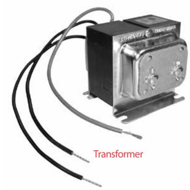
Function/Application: Transforms 120 volts AC to 24 volts AC. (To get 24 volts DC, use with 8WCON, AC to DC converter.) Typically used as a power supply for electrically-operated locks.
8WCON Features:
- 400 Ampere surge capability
- Electrically isolated base
- Specifications:
Average forward current – 25 amps
Case – Plastic case with an electrically isolated aluminum base
Polarity – Terminal designation embossed on case: +DC output, -DC output, AC not marked
Mounting position – Bolt down. Gain the highest heat transfer efficiency through the surface opposite the terminals. Use silicone heat sink compound on mounting surface for maximum heat transfer.
• UL recognized
Terminals – Suitable for "fast-on" connections. Readily solderable and corrosion resistant. Soldering is recommended for applications greater than15 amperes.
• Single-phase, full wave bridge
Mounting torque – 20 inch-pounds maximum
Case size – 1.030 x 1.030 inches
Temperature range – -85° to 347°F (-65° to + 175°C)
To order specify: 8WCON
Function/Application:
Converts AC (alternating current) to DC (direct current) for locking circuit applications. (Typically used with 8W599 transformer.)
8WBU-1-A / 8WBU-1-N Features:
- Positive "snap" feedback
- Industrial-grade switch designed for rugged control applications
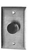
- Factory assembled with trimplate
Specifications:
Electrical rating – 28VDC or 115 VAC, 10A resistive, 5A inductive, 3A lamp load (see terminology on the back cover) Switch type – SPST-NO-DB, FORM-X contacts, 25,000 cycles at full load, 50,000 cycles mechanical life
Mounting hole – 5/8" (.625) dia.
Switch dim. – 1.187 dia.x 1.528 overall length
Standard wall plate – 2 3/4" x 4 1/2"
Narrow wall plate – 1 1/2" x 4 1/2"
Material/finish – Satin stainless steel
- Standard or narrow plate available
- 1 3/16" dia. mushroom head red in color
Two 6" long 20 AWG insulated wire leads To order specify – 8WBU-1-A standard plate 8WBU-1-N narrow plate To order specify: 8WCON
Function/Application:
Converts AC (alternating current) to DC (direct current) for locking circuit applications. (Typically used with 8W599 transformer.)
AC to DC Converter Full wave bridge rectifier
8WBU-1-A Standard plate
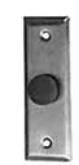
8WBU-1-N Narrow plate

ELECTRIFIED ACCESSORIES
Temperature control module Features
• All circuitry completely sealed
Specifications
- Wire leads: Input 24 AWG Stranded wire with PVC insulation (approx. 60" in length)
- Output 24 AWG Stranded wire with Teflon insulation (approx. 2.6" in length)
- Input Voltage: 12 or 24 volts AC or DC
- Output Voltage: Full voltage out @ 1 amp maximum for 0.5 seconds then 30% of voltage out for 5 seconds
- Output protection: Short circuit current limiting set at one (1) amp.
- Operating temp: -4 to 158°F (-20 to 70°C)
- Size: 1/2" x 2 1/4" x 1/2"
Function/Application
A temperature control module (TCM) reduces the amount of current flow to a lockset one second after energizing, thereby lowering the temperature of the lockset trim. A (TCM) also converts AC power to DC power and should be used on all electrified mortise and cylindrical locksets.
NOTE: The TCM is not used with any IDH-Max function.
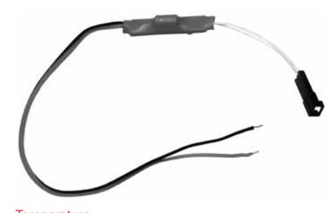
Temperature control module
TERMINOLOGY
Closed – A state in which a connection exists between the common terminal and another terminal on the switch. See Open also.
Common terminal – A terminal on a switch whose contact can be connected to one or more terminals on the switch.
Door status – A switch that monitors whether the door is open or closed. This switch is used to detect a forced entry, or a door that is propped open.
Inductive load – An electrical device such as a motor, relay, or solenoid.
NOTE: this type of load can cause arcing across switch contacts and may burn the contacts. See Resistive load and Lamp load also.
Latchbolt status – A switch that monitors whether the latch is engaged or retracted. This switch is used to detect a forced entry, or a latch that has been taped open.
Lamp load – An electrical device that produces light using a tungsten filament, such as an incandescent light bulb.
Note: this type of load can cause surges of current upon contact closure. This may cause the contacts to weld together. See Inductive load and Resistive load also.
Maintained – Remaining in a given state until the switch lever or button is actuated. Actuating the switch lever or button causes the switch to change to another maintained state.
Momentary – Remaining in a given state only as long as an external force is applied to the switch lever or button.
NC – (Normally Closed) Switch contacts that are closed as long as no external force is applied to the switch lever or button.
NO – (Normally Open) Switch contacts that are open as long as no external force is applied to the switch lever or button.
Open – A state in which no connection exists between the common terminal or any other terminal on the switch.
Pole – The number of independent circuits in a switch. For example, a double-pole, single-throw switch can control two separately powered motors.
See Throw also.
Resistive load – An electrical device, such as a heater, having none of the characteristics of an inductive or lamp load. This type of load is the least severe on the switch because only a small amount of arcing occurs when the switch contacts open and close. See Inductive load and Lamp load also.
RQE – Request-to-exit. A switch that allows the user to exit without setting off an alarm. Turning the inside knob or lever actuates the switch and, when wired to an alarm system, sends a signal to disable or sound an alarm, start a timer, etc.
Throw – The number of circuits, or contacts controlled by each pole. For example, a single-pole, double-throw switch can control a motor with two contacts—a forward contact, and a reverse contact. See Pole also.
1300 – Integrated BAS1300/LNL1300 reader electronics board or (ISC) Intelligent System Controller is embedded behind the escutcheon secured and out of site. Functions with Mercury on-line equipment only.
Electric Switch Lock – Introduction
BEST offers a line of electric switch locks available in various "on-off" and "momentary" keyed switch functions. Circuitry variations are available in single, double and triple pole with varied voltage and amperage ratings. Units may be keyed into any BEST® system. The BEST interchangeable core offers versatility and adaptability for new and existing electrical controls, panels, machines, etc.
Features
- Double D lock cylinder prevents slipping and turning
- Screw terminals on all switch locks (except the 1W7A1) provides ease of installation
- All switches are UL recognized or listed
Note on functionality: Switch lock keys can only be removed in the 12 o'clock position.
How to select a switch lock
-
1. Determine the electrical requirements for the device being controlled:
- A. Voltage (for example: 115 VAC or 24 VDC)
- B. Current or horsepower (for example: 6 amps or 1/2 horsepower)
C. Type of load
- Resistive (for example, heater elements)
- Inductive (for example, motors, large transformers)
- Lamp (for example, incandescent lights)
-
2. Determine the switch configuration (poles and throws) and key removal condition:
- A. Poles To determine the number of poles, find how many wires from the power source need to be switched on and off by the switch lock.
-
B. Throws To determine the number of throws, find how many wires to the device the switch needs to control. For example, if a switch needs two different "on" conditions (low and high speed), two throws are needed. Or if the device is simply an "on-off" type (only one wire), you need one throw.
- NOTE: A switch throw may be left unwired and used as an "off" condition.
- C. Key removal To determine the key removal condition, ask the question, "When the key is removed, should the switch be "off", or could the switch be either "on" or "off" ?" Although the key can only be removed in the 12 o'clock position, the switch itself may be left in two or three positions. Check each switch lock for key removal switch positions.
- 3. Use the information collected and find the switch lock that best meets the requirements. Refer to the following catalog pages for a description of each switch lock. If environmental conditions make it necessary that the switch lock be housed in an electrical box, see the Optional boxes below for the box that best suits the switch lock and your application.
Optional Boxes
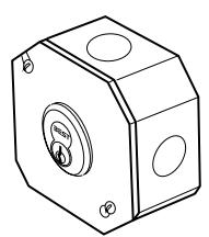
OC1 Standard octagon 3 1/2" x 3 1/2" x 1 5/8"
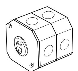
OC2 Deep octagon 3 1/2" x 3 1/2" x 3 1/4"
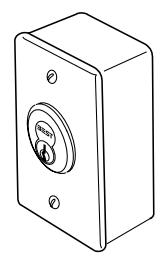
INT Interior box 4" x 2 1/8" x 1 7/8"
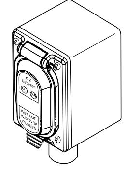
SWR Standard weather resistant box 4 5/8" x 2 7/8" x 3"
How To Order – 1W Electric Switch Lock
| 1W | 7 | B1 | 626 | SWR |
|---|---|---|---|---|
| Series | Core Housing | Function | Finishes | Box |
| 1W |
7–7 pin housing accepts all
BEST® cores |
see pages 15–19 |
605 606
611 612 613 619 622 625 626 690 |
OC1
OC2 INT SWR |

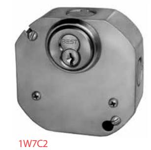
1W Electric Switch Locks
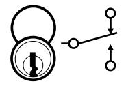
1W7A1
Contacts – Silver or gold flash Contact rating – 28 VDC, 10 amps resistive 28 VDC, 3 amps inductive, lamp 125 VAC, 10.1 amps resistive 250 VAC, 10.1 amps resistive
Horsepower rating – 125 VAC, 1/4 HP Operating temperature – -85°F to +257°F (-65° to +125°C) Switch type – SPDT (Single pole-double throw)
Switch lock action – Maintained Number of switches per assembly – One
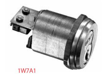
Key & switch positions Remove key Optional boxes
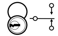
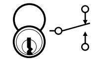
SWR INT OCT
Key pos.1– Swt. pos.1 Key pos.2– Swt. pos.2 Key pos. 1 only - Swt. pos. 1
1W7B1 & 1W7J1
Contact rating – 30 VDC, 15 amps, resistive 125 VDC, 0.6 amps, resistive 250 VDC, 0.3 amps, resistive 125 VAC, 15 amps, resistive 25 VAC, 5 amps, lamp 250 VAC, 15 amps, resistive
Horsepower rating – 125–250 VAC, 1/2 HP Operating temperature – -up to +176°F (+80°C) Switch type – SPDT (Single pole-double throw) Switch lock action – Maintained Number of switches per assembly –
1W7B1: One, 1W7J1: Two
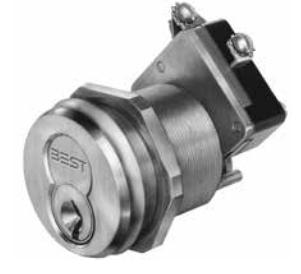
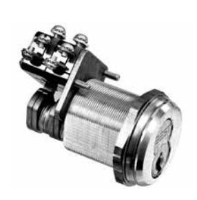
1W7B1—One switch
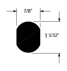
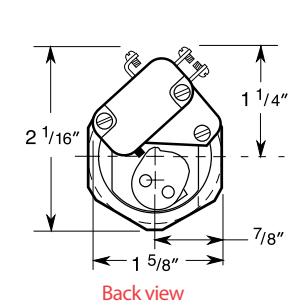
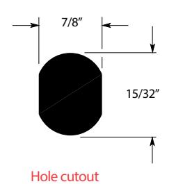
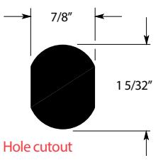
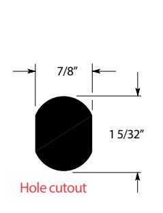
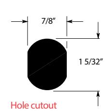
Hole cutout
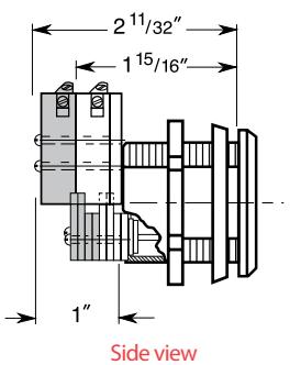
The shaded area shows the additional 1W7J1 switch and cam length.
1W7J1—Two switches
Key & switch positions Remove key Optional boxes
OC1 (1W7B1 only) OC2 INT SWR
Key pos.1– Swt. pos.1 Key pos.2– Swt. pos.2 Key pos. 1 only - Swt. pos. 1
1W Electric Switch Locks (Continued)
1W7B2 & 1W7J2
Contact rating – 0 VDC, 15 amps, resistive 125 VDC, 0.6 amps, resistive 250 VDC, 0.3 amps, resistive 125 VAC, 15 amps, resistive 125 VAC, 5 amps, lamp 250 VAC, 15 amps, resisti
Horsepower rating – 125–250 VAC, 1/2 HP Operating temperature – up to +176°F (+80°C) Switch type – SPDT (Single pole-double throw) Switch lock action – Maintained Number of switches per assembly – 1W7B2: One, 1W7J2: Two
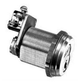
1W7B2—One switch
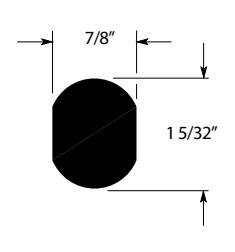
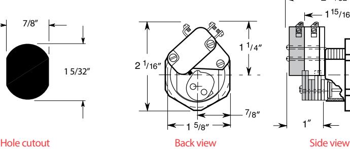
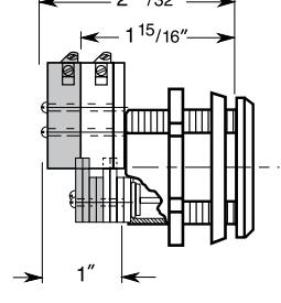
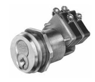
1W7J2—Two switches The shaded area shows the additional 1W7J2 switch and cam length.
Key & switch positions Remove key Optional boxes
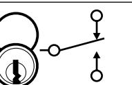
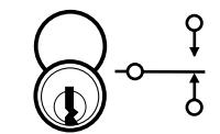
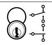
OC1 (1W7B2 only) OC2 INT SWR
Key pos.1– Swt. pos.1 Key pos.2– Swt. pos.2
(360°CCW)
Key pos. 1 only - Swt. pos. 1 Swt. pos. 1 and 2
1W7B3 & 1W7J3
Contact rating – 30 VDC, 15 amps, resistive 125 VDC, 0.6 amps, resistive 250 VDC, 0.3 amps, resistive 125 VAC, 15 amps, resistive 125 VAC, 5 amps, lamp 250 VAC, 15 amps, resistive
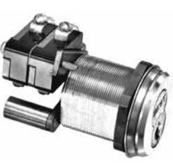
Horsepower rating – 125–250 VAC, 1/2 HP Operating temperature – up to +176°F (+80°C) Switch type – SPDT (Single pole-double throw) Switch lock action – Momentary Number of switches per assembly – 1W7B3: One, 1W7J3: Two
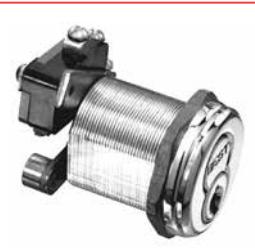
1W7B3—One switch
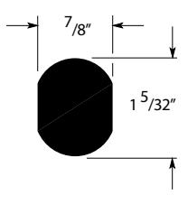
Hole cutout
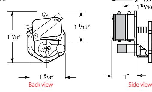
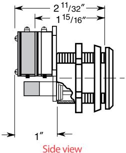
The shaded area shows the additional 1W7J3 switch and cam length.
1W7J3—Two switches
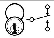
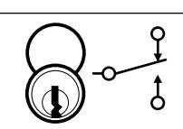
Key & switch positions Remove key Optional boxes
OC1 (1W7B3 only) OC2 INT SWR
Key pos.1– Swt. pos.1 Key pos.2– Swt. pos.2 Key pos. 1 only - Swt. pos. 1

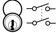
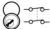
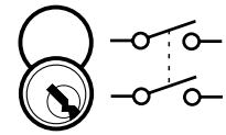
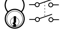
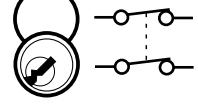
1W7D2
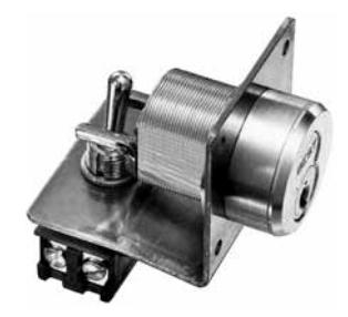
Contact rating – 110 VAC or VDC, 16 amps, resistive 220 VAC or VDC, 8 amps, resistive Horsepower rating – 1 HP @ 125–250 VAC or VDC
Operating temperature – 0°F to +150°F (-18°C to +66°C) Switch type – DPST (Double pole-single throw) Switch lock action – Maintained Number of switches per assembly – One
1W7D2
Key & switch positions Remove key Optional boxes
SWR
Key pos.1– Swt. pos.1 Key pos.2– Swt. pos.2 Key pos. 1 only - Swt. pos. 1
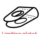
†Installing the limiting plate limits key removal to switch position 1 or 2. The key is always removed in the vertical position (key position 1).
1W7B2 & 1W7J2
Contact rating – 110 VAC or VDC, 10 amps, lamp 220 VAC or VDC, 5 amps, resistive
Operating temperature – -40°F to +150°F (-40° to +65°C)
Switch type – SPST (Single pole-single throw) Switch lock action – Maintained Number of switches per assembly – One
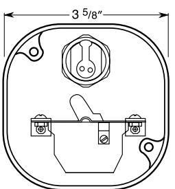
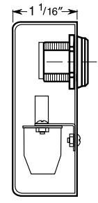
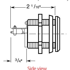
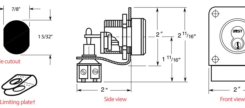
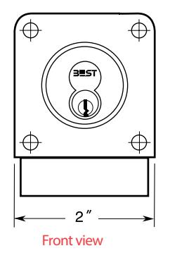
Front (inside) view Side (inside) view
Key & switch positions Remove key Optional boxes
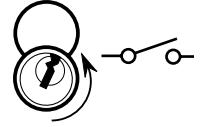
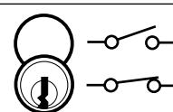
Key pos.1– Swt. pos.1 Key pos.2– Swt. pos.2 Key pos. 3 only Swt. pos. 1 and 2
OC1-SPL
1W Electric Switch Locks (Continued)
1W7E2
Contact rating – 110 VAC, 15 amps, resistive 220 VAC, 10 amps, resistive
Horsepower rating – 125–250 VAC or VDC, 3/4 HP; 1, 2, or 3 phase
Operating temperature – 0 to +150°F (-18°C to 66°C)
Switch type – TPDT (Triple pole-double throw)
Switch lock action – Maintained
Number of switches per assembly – One
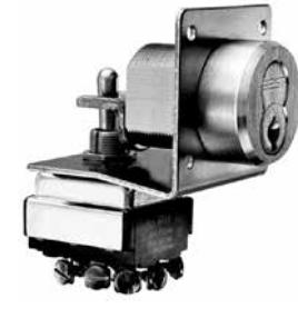
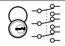
1W7E2
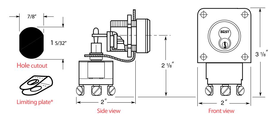
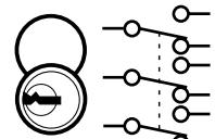
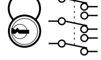
Key & switch positions Remove key Optional boxes
SWR
Key pos.1 Swt. pos.1
Key pos.2 Swt. pos.2
Key pos. 1 only Swt. pos. 1
Key pos. 1 only Swt. pos. 1, 2, and 3*†
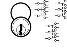
1W7E2
Contact rating – 110 VAC, 15 amps, resistive 220 VAC, 10 amps, resistive Horsepower rating – 250 VAC, 1/2 HP
Operating temperature – up to +221°F (+105°C)
Switch type – DPDT (Double pole-double throw) Switch lock action – Momentary Number of switches per assembly – One
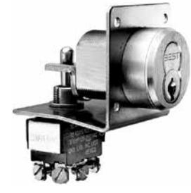
1W7K4
Key & switch positions Remove key Optional boxes
SWR
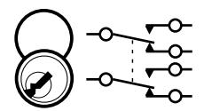
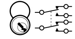
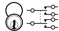
Key pos.1 Swt. pos.1
Key pos.2 Swt. pos.2
Key pos. 1 only Swt. pos. 1
Key pos. 1 only Swt. pos. 1, 2, and 3*†
* Installing the limiting plate limits key removal to switch position 2, or 3. The key is always removed in the vertical position (key position 1).

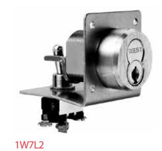
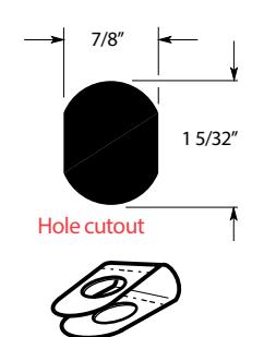
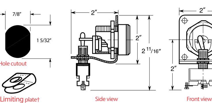
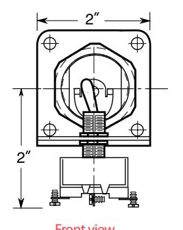
1W7L2
Contact rating – 110 VAC or VDC, 12 amps, resistive 220 VAC or VDC, 6 amps, resistive Operating temperature – up to +221°F (+105°C)
Switch type – SPDT (Single pole-double throw) Switch lock action – Maintained Number of switches per assembly – One
SWR
Key & switch positions Remove key Optional boxes
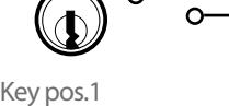
Key pos.2 Swt. pos.2
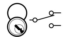
Key pos. 1 only Swt. pos. 1
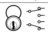
Key pos. 1 only Swt. pos. 1, 2, and 3*†
†Installing the limiting plate limits key removal to switch position 1 or 2. The key is always removed in the vertical position (key position 1).
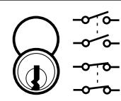
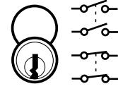
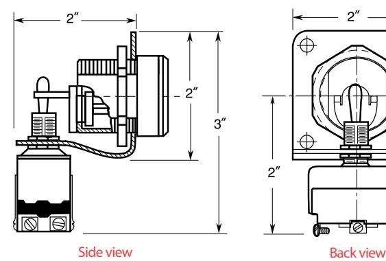
1W7P4 & 1W7R4
Swt. pos.1
Contact rating – 30 VDC, 15 amps, resistive 125 VDC, 0.6 amps, resistive 250 VDC, 0.3 amps, resistive 125 VAC, 15 amps, resistive 125 VAC, 5 amps, lamp 250 VAC, 15 amps, resistive
Horsepower rating – 125–250 VAC, 1/2 HP Operating temperature – up to +176°F (+80°C Switch type – SPDT (Single pole-double throw) Switch lock action – Momentary Number of switches per assembly – 1W7P4: Two, 1W7R4: Four
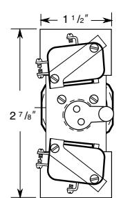
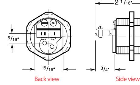
Back view Side view
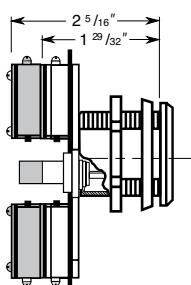
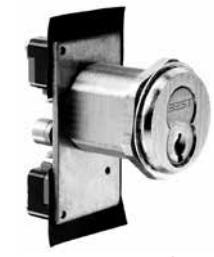
1W7P4—two switches
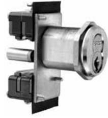
1W7R4—four switches
The shaded area shows the additional 1W7R4 switches and cam length.
Key & switch positions Remove key Optional boxes
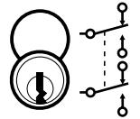
Key pos.1 Swt. pos.1
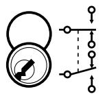
Key pos.2 Swt. pos.2
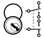
Key pos. 1 only Swt. pos. 1
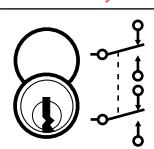
Key pos. 1 only Swt. pos. 1, 2, and 3*†
SWR INT (1W7P4 only)
BEST Quick Connect System
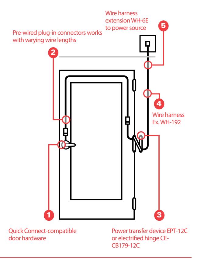
BEST Quick Connect plug-in connectors must be used with the following components to work as a complete plug-and-play system:
- 1. Specify appropriate PRECISION or BEST electrified products
- 2. Specify correct wire harness length from door hardware to electric power transfer device or electrified hinge
- 3. Specify either the NEW electric power transfer (EPT-12C) or the NEW electrified hinge (CECB179-12C)
- 4. Specify correct wire harness length from power transfer or electrified hinge to wire extension (WH-6E)
- 5. Choose wire harness extension to connect to power source
How To Order
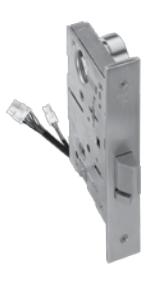
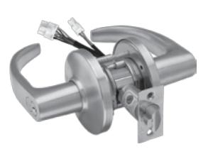
To order the BEST Quick Connect pre-wired plug-in connectors, include the "C" suffix for the BEST electrified locks. See example below.
Example: BEST Locks 45HW 7 DEL 14H 626 RH DSC
BEST Locks 9KW 37 DEU 15CS TK 626 24 VC

6161 East 75th Street Indianapolis, IN 46250 USA
Phone 855-365-2407
bestaccess.com