Arrow Lock & Door Hardware Door Opreators 7814U 7836U Universal Instruction
Open the original PDF document
View PDF

7800 Series Low Energy Power Operator Installation and Instruction Manual
ASSA ABLOY
80-9357-0001-040 (10-10)
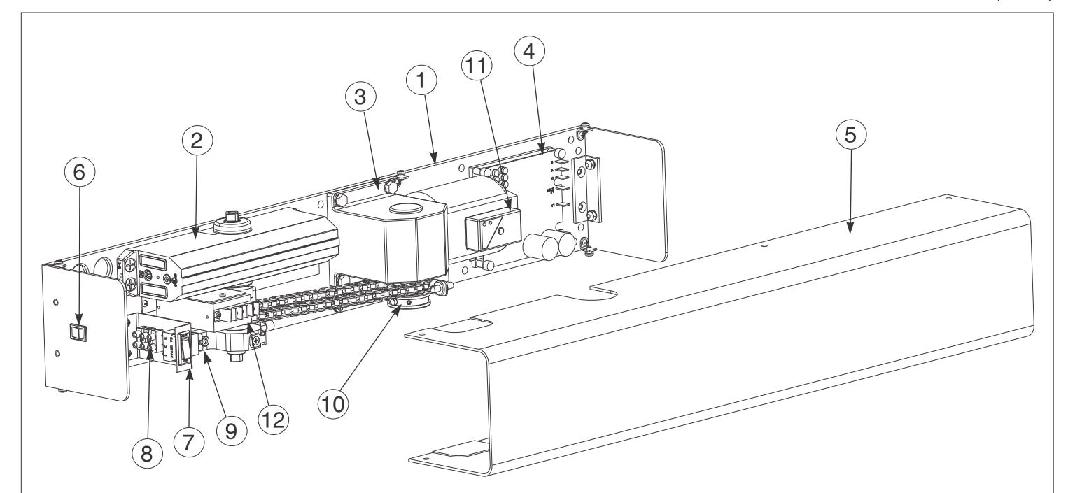
| Item No. | Description |
|---|---|
| 1 | Back plate |
| 2 | Door Closer (914BO / 936BO) |
| 3 | Motor Assembly (7800MA) |
| 4 | Inverter (7800IN) |
| 5 | Cover (7800CO) |
| 6 | On/Off switch |
| 7 | Circuit Breaker |
| 8 | 120VAC Electrical Connections |
| 9 | Activation Inputs |
| 10 | Door Open/Closed Position Magnets |
| 11 | Optional RF Receiver |
| 12 | Power Supply - 1.1A 24V |
Tools required:
- 1/8" allen wrench (included)
- Flat blade screwdriver (potentiometer & terminal size)
- Screwdriver (Phillips size 2)
- Tape ruler
- · Power drill and set of drill bits
- Center punch
- Wire stripper
- #7 drill 1/4-20 tap (metal frame install)

WARNINGS
- Always disconnect the main power to the operator prior to servicing or cleaning.
- To reduce the risk of injury or person, use the operator only with Pedestrian Swing doors.
- This operator is for indoor use only.
- 120VAC power supplied to the operator must be a dedicated circuit from the main circuit breaker panel and must NOT be connected into any building lighting system that operates flourescent lights.
- Maximum door size: 48 in (1219mm) wide x 250 lb (113.4kg).
| Con | tents | ||
|---|---|---|---|
| General | 2 | Stop (Push) Side Installation | 6 |
| Frame Reinforcement Table | 2 | Electrical Installation | 7 |
| Component Layout | 3 | Input Power Configuration | 8 |
| ADA / ANSI / ÚL | 3 | Inverter Details | 9 |
| Hinge (Pull) Side Mounting | 4 | Accessory / Typical Installations | 9 |
| Hinge (Pull) Side Installation | 4 | Troubleshooting | 11 |
| Stop (Push) Side Mounting | 6 | 3 |
General Information
- UL labeled fire or smoke barrier door assemblies require that the 120VAC (60Hz) power input to the 7800 door operator be supplied through normally closed alarm contacts of the alarm system / alarm panel.
- Power input to 7800 door operator must be 120VAC (60Hz) to terminals HOT and COM at terminal strip T1. Earth ground (GND) to green screw on backplate.
- All wiring must conform to standard wiring practice in accordance with national and local wiring codes.
- Note: Unless otherwise noted, all dimensions are given in inches (millimeters).
- Minimum suggested and required material thickness for hollow metal frames (skin plus reinforcement) is charted on below.
- Unit is Non-Handed.
- Door must be hung on butt hinges [5" (127mm) max. width] or 3/4" (19mm) offset pivots. A separate door and frame preparation template will be supplied for other conditions.
- Door must swing freely through the entire opening and closing cycle before beginning the installation.
- Use of an auxiliary door stop (by others) is always recommended.
- An incorrectly installed or improperly adjusted door operator can cause property damage or personal injury. These instructions should be followed to avoid the possibility of misapplication or misadjustment.
WARNING: Make sure 120VAC (60Hz) input power is turned off at facility's main circuit breaker before proceeding with installation.
General Templating Information:
- Before beginning the installation, verify that the door frame is properly reinforced and is well anchored in the wall.
- Unreinforced hollow metal frames and aluminum frames should be prepared and fitted with 1/4-20 blind rivet nuts, furnished by others.
- Concealed electrical conduit and concealed switch or sensor wires should be pulled to the frame before proceeding.
Fasteners for Frame:
- 1/4-20 machine screws for hollow metal and aluminum.
- No. 14 x 2-3/4" (70mm) long sheet metal screws for wood.
Fasteners for Door:
- 1/4-20 machine screws.
- 3/8" diameter x 1-5/8" (41mm) long sex nut.
Electrical Information:
- Maximum current draw of unit is 0.6 amps.
- Breaker Switch protects the motor assembly and inverter; and has a 5 amp rating.
-
Maximum wire size is:
- 12AWG at terminals HOT and COM (120VAC; 60Hz) on "T1" Power Input Terminal.
- 14AWG at terminals 1 thru 4 on Accessory Terminal . 18AWG at terminals 22 thru 25 on "T1" Power Input Terminal.
Frame Reinforcement Table
| Hollow Metal Door Frame Reinforcing | |||
|---|---|---|---|
| Frame | Reinforcing | ||
| Material | Recommended | Min. Required | |
|
12 Ga.
. 1046 (2.66) |
12 Ga.
.1046 (2.66) |
18 Ga.
. 0478 (1.21) |
|
|
14 Ga.
. 0747 (1.90) |
10 Ga.
. 1343 (3.41) |
12 Ga.
.1046 (2.66) |
|
| 16 Ga. . 0598 (1.52) |
10 Ga.
. 1343 (3.41) |
12 Ga.
.1046 (2.66) |
|
|
18 Ga.
. 0478 (1.21) |
8 Ga.
. 1644 (4.18) |
10 Ga.
. 1343 (3.41) |
|
Component Layout
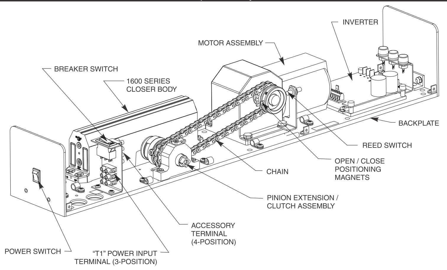
Included with 7814H and 7836H
Included with 7814S and 7836S
ADA / ANSI / UL Information
Americans With Disabilities Act (A.D.A.)
These door operators can be installed and adjusted to conform with A.D.A. regulations.
ANSI Standards
ANSI A117.1 – These door operators permit door assemblies to conform to the requirements of this specification "for buildings and facilities – providing accessibility and usability for physically handicapped people".
ANSI A156.19 – These products are designed to conform to this specification "for power assist and low energy power operated doors".
- "PAS" Function is designed to meet or exceed all of the requirements for the "Power Assist Door".
- "POR" Function is designed to meet or exceed all of the requirements for the "Low Energy Power Operated Door".
U.L. Listing

Underwriters Laboratories, Inc. listed for use on fire and smoke barrier door assemblies when the 120VAC (60Hz) power input is supplied through the normally closed alarm contacts of a compatible UL Listed alarm system or alarm panel.
80-9359-0001-040 (10-10) Page 3
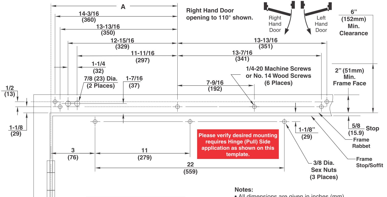
1. Hinge (Pull) Side Mounting Instructions
6" (152mm) Min. Ceiling Clearance Door 2" (51mm) Min. Frame Face Frame Reveal 1-3/4" (44mm) Min. 2-1/4" (57mm) Max. Door Thickness
Door Opening
Angle
Up to 110°
111° to 180°
🗜 Hinge
Dim "A"
15-1/2 (394)
13-1/4 (337)
- · All dimensions are given in inches (mm).
- Thickness recommended for reinforcements in hollow metal doors and frames is charted on Page 2.
- Do not scale drawing.
- Left hand door shown.
- This template information based upon use of 5" (127mm) maximum width butt hinges. A separate template is required for other conditions.
- Maximum frame reveal is 6-7/8" (175mm) for this application.
- Conduit hole nearest the hinge is suggested for 120 VAC power input.
Note: Door must be visible by person operating activation switch(es)
Installation Sequence
- Step 1: Determine hand of door from illustration on upper right of this
- Step 2: Using template above locate and prepare holes in the frame & door:
- A. Prepare six (6) holes for 1/4-20 machine screws or No. 14 x 2-3/4" (70mm) wood screws. Blind rivet nuts (by others) are suggested for unreinforced hollow metal frames or for aluminum frames.
- B. Concealed Wired Units Only: Two (2) 7/8" (22mm) diameter holes for conduit, for power input and for switch/sensor wires. NOTE: On new construction these holes will generally be drilled by the frame supplier at their shop or at the time the frame is installed in the wall.
C. Prepare three (3) holes for 3/8" diameter sex nuts. Standard units
are supplied with sex nuts and screws for 1-3/4" (44mm) thick door. Sex nuts and screws for other door thicknesses are available to order.
Step 3: Remove cover from the unit and set cover & cover screws aside.
Step 4: Mount unit to door frame. Select A or B below.
- A. Concealed Wired Units Only: Connect conduit to frame side of backplate. Fasten unit to door frame (seven screws).
- Surface Wired Units Only: Fasten unit to door frame (seven screws). Mount conduit bracket (found in screw pack) to unit's backplate with two screws provided. Connect wiring conduit to bracket.
- Step 5: Mount track assembly to door using 3 1/4-20 screws & sex nuts with buffer assembly toward hinge. Open part of track to face top of door.
(Continue to next page.)
1A. Installation Sequence Continued
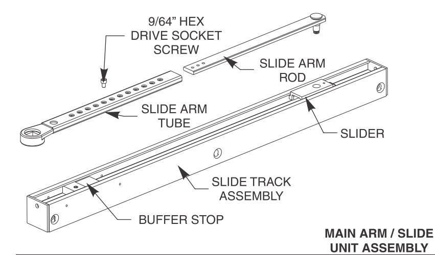
Step 6: Insert slide arm rod into slide arm tube setting the distance between the pinion square and the slide stud at 13-1/2" (343). Install 9/64" hex drive socket head screw from screw pack. (See illustration below)
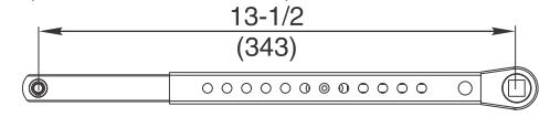
Note: Center threaded hole of slider arm should align with seventh hole of the slider tube
Step 7: Using an adjustable wrench, rotate pinion 45° toward hinge, as shown below. With the arm assembly parallel to the door, secure arm to pinion when square of the pinion aligns with the square in the arm. Secure with countersunk washer and 1/4-20 Flat Head Screw (with thread lock) provided. Tighten screw with 7/16" wrench or socket.
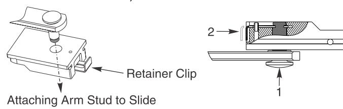
Step 8: Insert arm stud into slide block in track assembly. Secure by pushing in on the retainer clip that extends from the slide block in the track, until it is flush with the slide block (see illustration below).
Step 9: Adjust closing power of unit (See Fig. 1) - Using a 1/8" allen wrench, turn the power adjustment shaft clockwise to increase door closing power. Door control is shipped set at midpoint of power setting. Maximum closing power can be achieved with 8 (360°) clockwise turns of the power adjustment screw.
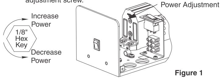
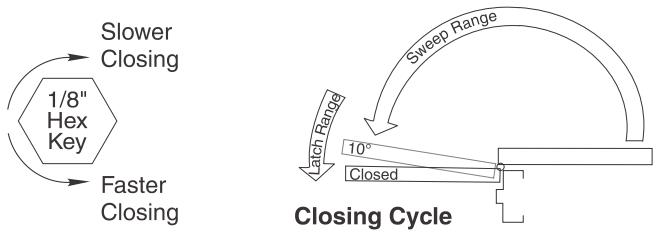
Step 10: Adjust Hydraulic valves using a 1/8" hex wrench to obtain proper door closing speeds. See following illustrations. Refer to Table 1 below for recommended minimum opening / closing times per ANSI/BHMA A156.19.
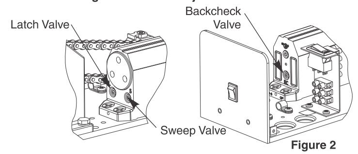
Closing Cycle – Make adjustments, as necessary, to the Sweep Speed "S" valve and Latch Speed "L" valve. See Fig. 2 below for location of valves. Turn valves clockwise to reduce speed, counter clockwise to increase speed.
Opening Cycle – Adjust Backcheck, "B" valve, as necessary, for hydraulic resistance to door opening in the backcheck range. See illustration in Fig. 2 for location of valve.
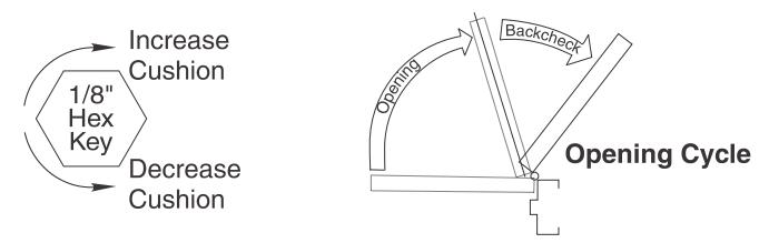
NOTE: Too much Backcheck, "B" valve, can affect the operation of the units pump, preventing units from fully opening the door. This valve may require fine tuning after all other adjustments have been made.
Note: A.D.A. requires that from an open position of 70°, the door will take at least 3 seconds to move to a point 3" (75mm) from the latched position, measured at the leading edge of the door.
Step 11: Make wiring connections using Wiring Instructions on Page 7.
Table 1 - Minimum Opening / Closing Times for ANSI/BHMA A156.19
|
Door Leaf
Width - |
Door Weight in Pounds (kg) | ||||
|---|---|---|---|---|---|
| Inches (mm) | 100 (45.4) | 125 (56.7) | 150 (68.0) | 175 (79.4) | 200 (90.7) |
| 30 (762) | 3.0 | 3.0 | 3.0 | 3.0 | 3.5 |
| 36 (914) | 3.0 | 3.5 | 3.5 | 4.0 | 4.0 |
| 42 (1067) | 3.5 | 4.0 | 4.0 | 4.5 | 4.5 |
| 48 (1219) | 4.0 | 4.5 | 4.5 | 5.0 | 5.5 |
Matrix values are in seconds.
Backcheck - adjust the backcheck valve to have a minimum opening time to backcheck or 80 degrees (whichever comes first) based on Table 1.
Closing Time - adjust Latch and Sweep valves to have a minimum closing time from 90 degrees to Latch Check or 10 degrees (whichever comes first) based on Table 1.
2. Stop (Push) Side Mounting Instructions Right Left Hand Hand В Left Hand Door Door Door 14-3/16 open to 110° shown. (360)13-13/16 13-13/16 (351)(351)12-15/16 13-7/16 (329)(341)1/4-20 Machine Screws 11-11/16 or No. 14 Wood Screws (297)(6 Places) 5-1/4" 1-1/4 11/16 7-9/16 Min. (32)(17.5)(192)Clearance 7/8 5/8 Frame Frame Stop 1-11/16 (15.9)Stop/Soffit Rabbet (Conduit Holes -(43) 2 Places) 3/8 1-3/4 Dia. (19)(44) Sex Nuts Please verify desired mounting Notes: (2 Places) requires Stop (Push) Side All dimensions are given in inches (mm). application as shown on this • Thickness recommended for reinforcements in template. hollow metal doors and frames is charted at the left of this page. Door Opening Do not scale drawing. Hinge or Pivot Dim "A" Dim "B" · Left hand door shown. Angle This template information based upon use of 5" Up to 110° 12 (305) 15-3/4 (400) (127mm) maximum width butt hinges or 3/4" 111° to 170° 9-1/2 (241) 13-1/4 (337) (19mm) offset pivots. A separate template will be supplied for other conditions. • Maximum frame reveal is 7" (178mm) for this application. 5-1/4" (133mm)
Note: Door must be visible by person operating activation switch(es)
Door
Min. Ceiling
Clearance
2A. Installation Sequence
1-3/4" (44mm) Min. Door Thickness
2-1/4" (57mm) Max.
- Step 1: Determine hand of door from illustration on upper right of this page.
- Step 2: Using template above locate and prepare holes in the frame & door:
Frame
1-1/2" (38mm)
Min. Frame Face
Frame Reveal*
- A. Prepare six (6) holes for 1/4-20 machine screws or 14 x 2-3/4" (70mm) wood screws. Blind rivet nuts (by others) are suggested for unreinforced hollow metal frames or for aluminum frames.
- B. Concealed Wired Units Only: Two (2) 7/8" (22mm) diameter holes for conduit, for power input and for switch/sensor wires. NOTE: On new construction these holes will generally be drilled by the frame supplier at their shop or at the time the frame is installed in the wall.
Door
Prepare two (2) holes for 3/8" diameter sex nuts. Standard units are supplied with sex nuts and screws for 1-3/4" (44mm) thick door. Sex nuts and screws for other door thicknesses are available to order.
120 VAC power input.
assembly.
Conduit hole nearest to hinge is suggested for
*For frame reveals less than 3" (76mm) the
arm adjusting rod can be field cut to a length of 9-1/2" (241mm) measured from
centerline of connecting link bushing
- Step 3: Remove cover from the unit and set cover & cover screws aside.
-
Step 4: Mount unit to door frame. Select A or B below.
- A. Concealed Wired Units Only: Connect conduit to frame side of backplate. Fasten unit to door frame (six screws).
- B. Surface Wired Units Only: Fasten unit to door frame (six screws). Mount conduit bracket (found in screw pack) to unit backplate with two screws provided. Connect wiring conduit to bracket.
2A. Installation Sequence Continued
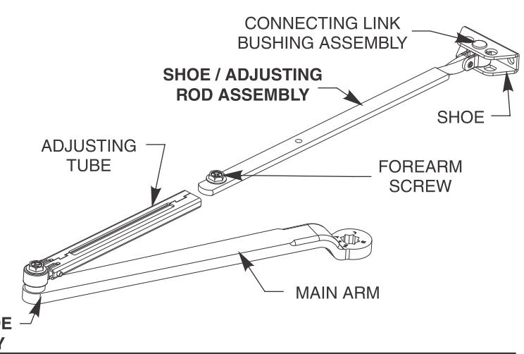
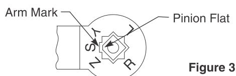
Step 5: Install main arm onto pinion shaft of unit at a 90° angle to the door frame. Align arm mark "S" with the flat corner of the pinion shaft square. (See Fig. 3 below.)
- Step 6: Secure main arm to pinion with 1/4-20 Flange Head Screw provided. Tighten screw with 7/16" wrench or socket.
- Step 7: Mount arm shoe to door using 2 1/4-20 screws & sex nuts provided with screw pack.
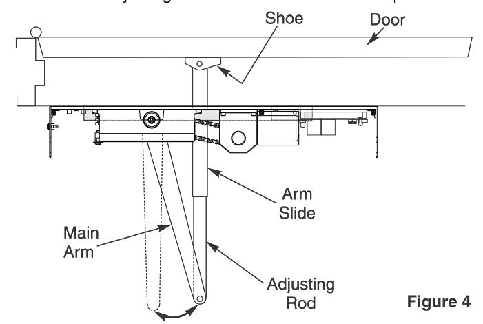
- Step 8: PRELOAD ARM (See Fig. 4, below): Remove 1/4-20 hex head screw on adjusting rod and insert adjusting rod into arm slide. Reinstall 1/4-20 screw and leave loose. Rotate main arm in direction away from the hinge edge until the adjusting rod and arm slide are perpendicular (at a 90° angle) to the door frame. Tighten the 1/4-20 hex head screw on the adjusting rod to secure arm in this new position.
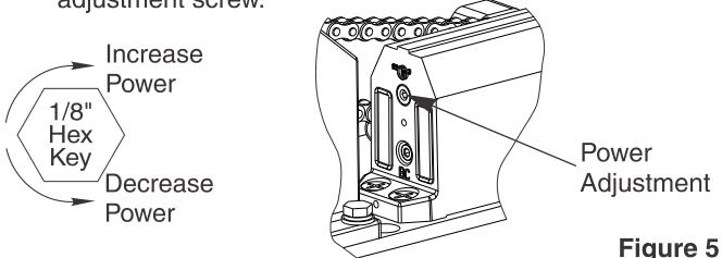
Step 9: Adjust closing power of unit (See Fig. 5) - Using a 1/8" allen wrench, turn the power adjustment shaft clockwise to increase door closing power. Door control is shipped set at midpoint of power setting. Maximum closing power can be achieved with 8 (360°) clockwise turns of the power adjustment screw.
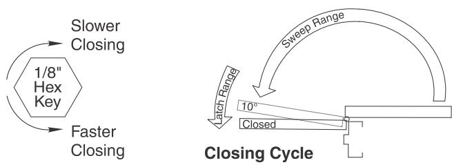
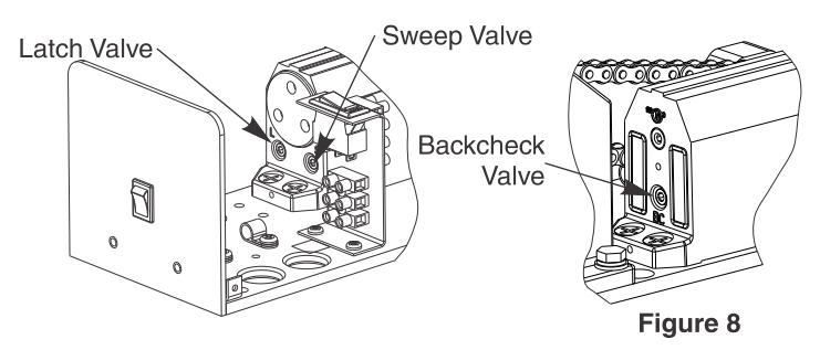
Step 10: Adjust Hydraulic valves using a 1/8" hex wrench to obtain proper door closing speeds. See following illustrations. Refer to Table 1 on page 5 for recommended minimum opening / closing times per ANSI/BHMA A156.19.
Closing Cycle - Make adjustments, as necessary, to the Sweep Speed "S" valve and Latch Speed "L" valve. See Fig. 6 below for location of valves. Turn valves clockwise to reduce speed, counter clockwise to increase speed.
Opening Cycle - Adjust Backcheck, "B" valve, as necessary, for hydraulic resistance to door opening in the backcheck range. See illustration at bottom of this page for location of valve.
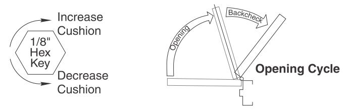
NOTE: Too much Backcheck, "B" valve, can affect the operation of the units pump, preventing units from fully opening the door. This valve may require fine tuning after all other adjustments have been made.
Note: A.D.A. requires that from an open position of 70°, the door will take at least 3 seconds to move to a point 3" (75mm) from the latched position, measured at the leading edge of the door.
Step 11: Make wiring connections using Wiring Instructions on Page below and on Page 8..
3. Electrical Connections and Final Setup
- Step 1: Confirm all mechanical adjustments have been made and wiring connected per Page 8.
- Step 2: Turn on facility's main circuit breaker.
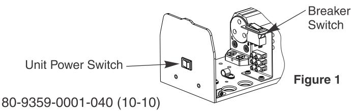
- Step 3: Turn power to unit on at the Unit Power Switch and turn the Breaker Switch to "RESET".
Step 4: Using a short jumper cable, jump terminals 1 and 2, see Fig. 2 below, to activate unit. When door reaches 20°, switch Breaker Switch to "OFF" position cutting power to the unit. Allow door to fully close (door may be manually pulled closed).
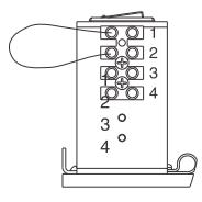
Figure 2
(Continue to next page.)
3. Electrical Connections and Final Setup Continued
Step 5: Adjust Closing Position Magnet (See Fig. 3) - With door in the closed position, use finger to slide Closed Position Magnet so it aligns directly with the Reed Switch.
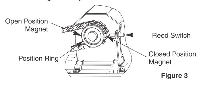
Step 6: Adjust Open Position Magnet - Use fingers to slide Open Position Magnet 180° from Open Position Magnet.
- Step 7: Flip Breaker Switch to "RESET" to turn power on. Jump terminals 1 and 2 (as shown in Fig. 2) to activate door. Note open position of the door. Allow door to close.
- Step 8: Use finger to readjust the Open Position Magnet to desired door open position.
- Step 9: Repeat Step 7 to verify door open position.
- Step 10: Make all connections necessary for any accessories to the 4-position Accessory Terminal (see Pages 9 118).
- Step 11: Make necessary adjustments to inverter (see Page 9). Replace cover and cover screws.
Input Power Configurations
CONCEALED WIRING
Thread conduit fitting(s) into backplate as shown. A second conduit fitting is required for low voltage control wiring. CHECK LOCAL CODES. Pull conduit out of header and attach to conduit fittings before mounting Operator to door frame. Attach incoming ground wire to backplate with ground screw as illustrated in "Surface Wiring" illustration to the Right.
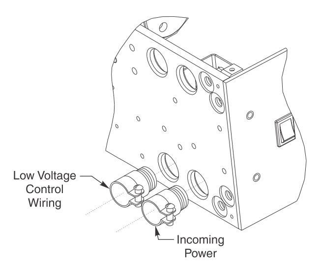
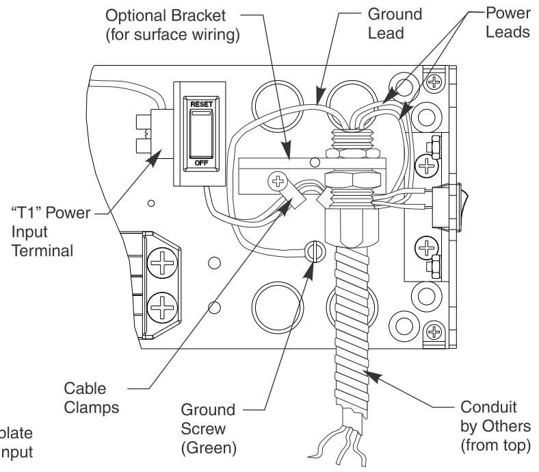
Ground Wire Connection – Ground wire must be secured to backplate under head of (green) ground screw nearest to "T1" Power Input Terminal. Screw labeled "GND".
SURFACE WIRING
An optional bracket is provided for use with surface wiring. Remove the two cable clamps screws and slip the bracket under the cable clamps. Push the cable clamp screw through the bracket holes and tighten. ½" conduit fittings can now be installed on the bracket. Attach incoming ground wire to backplate with ground screw as illustrated below.
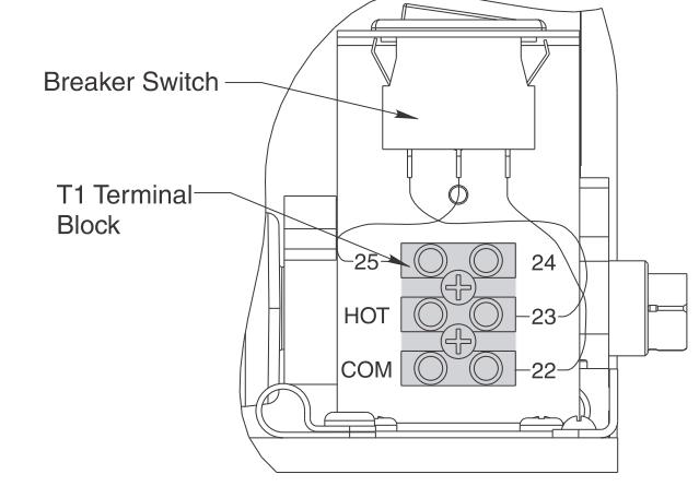
| Terminal | Description |
|---|---|
| COM | Common power lead |
| HOT | Hot power lead |
| 25 | Circuit Breaker |
| 24 | Switch |
| 23 | Circuit Breaker |
| 22 | Common connection to Circuit Breaker / Inverter |
Page 8 80-9357-0001-040 (10-10)
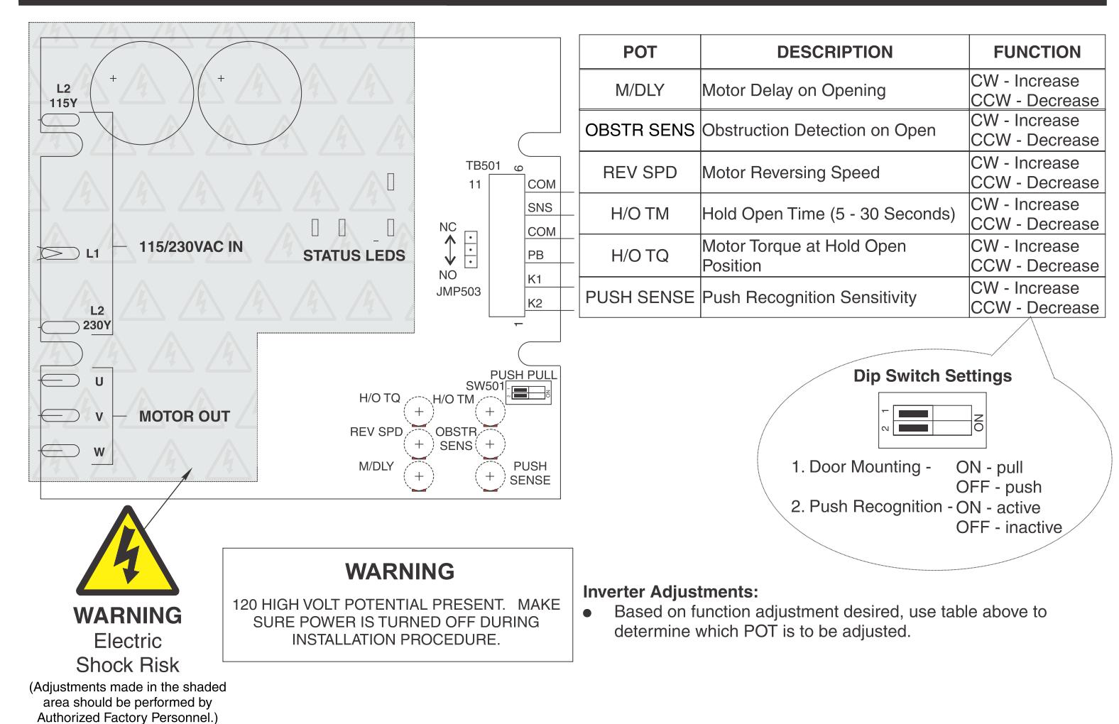
Inverter Details
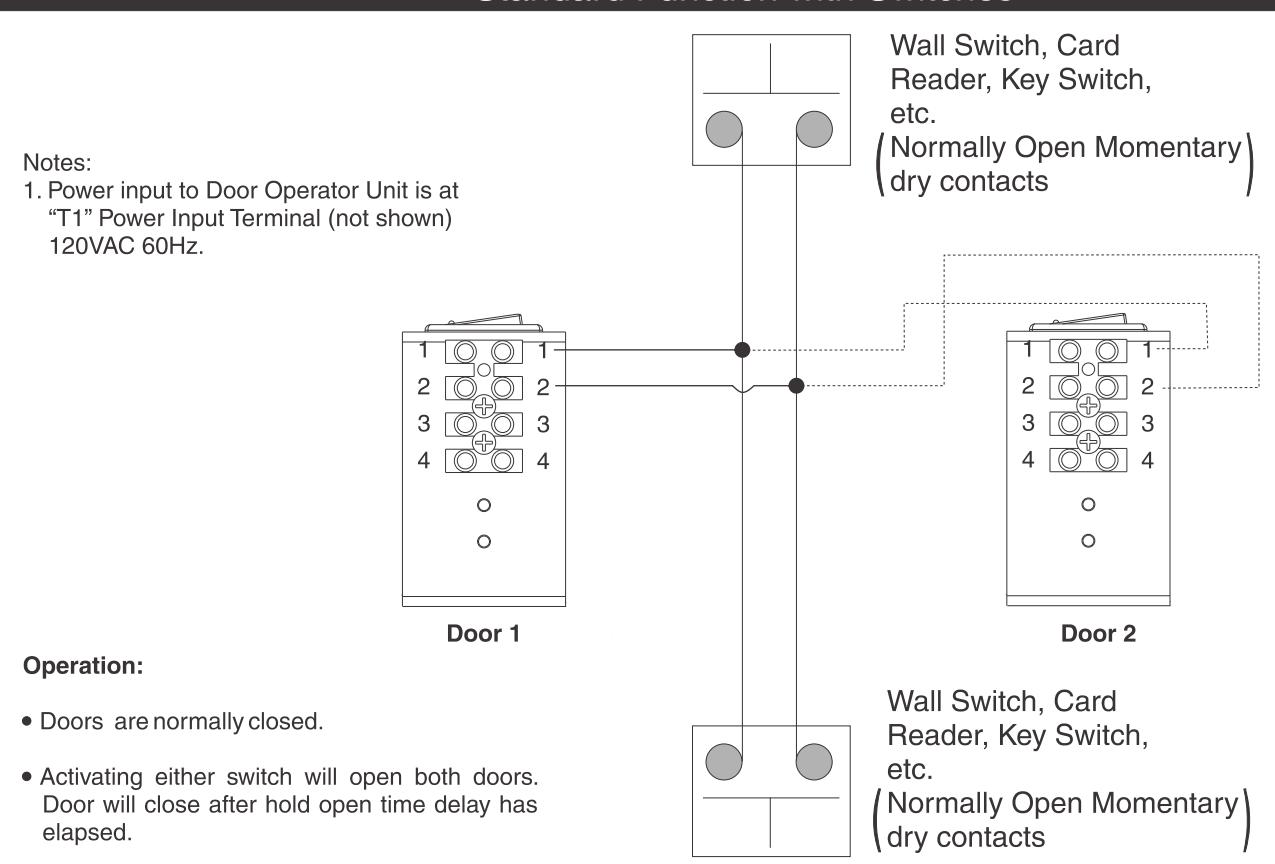
Standard Function with Switches
80-9359-0001-040 (10-10) Page 9
Radio Frequency Function Option
- 1. Power input to Door Operator Unit is at "T1" Power Input Terminal (not shown) 120VAC 60Hz.
- 2. Radio Frequency Feature can be purchased as a separate kit.
Optional 1.1A 24V Power Supply
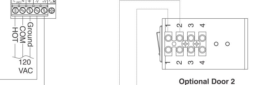
RF ORANGE RECEIVER WIRING FOR BLACK BOARD MOMENTARY (PART OF HOLD OPEN BROWN/WHITE OPERATOR FUNCTION UNIT) RED
Operation:
- Door is normally closed.
- Activating wireless switch or hand held wireless transmitter will open the door.
Door 1
0 0
Door will close after hold open delay elapses.
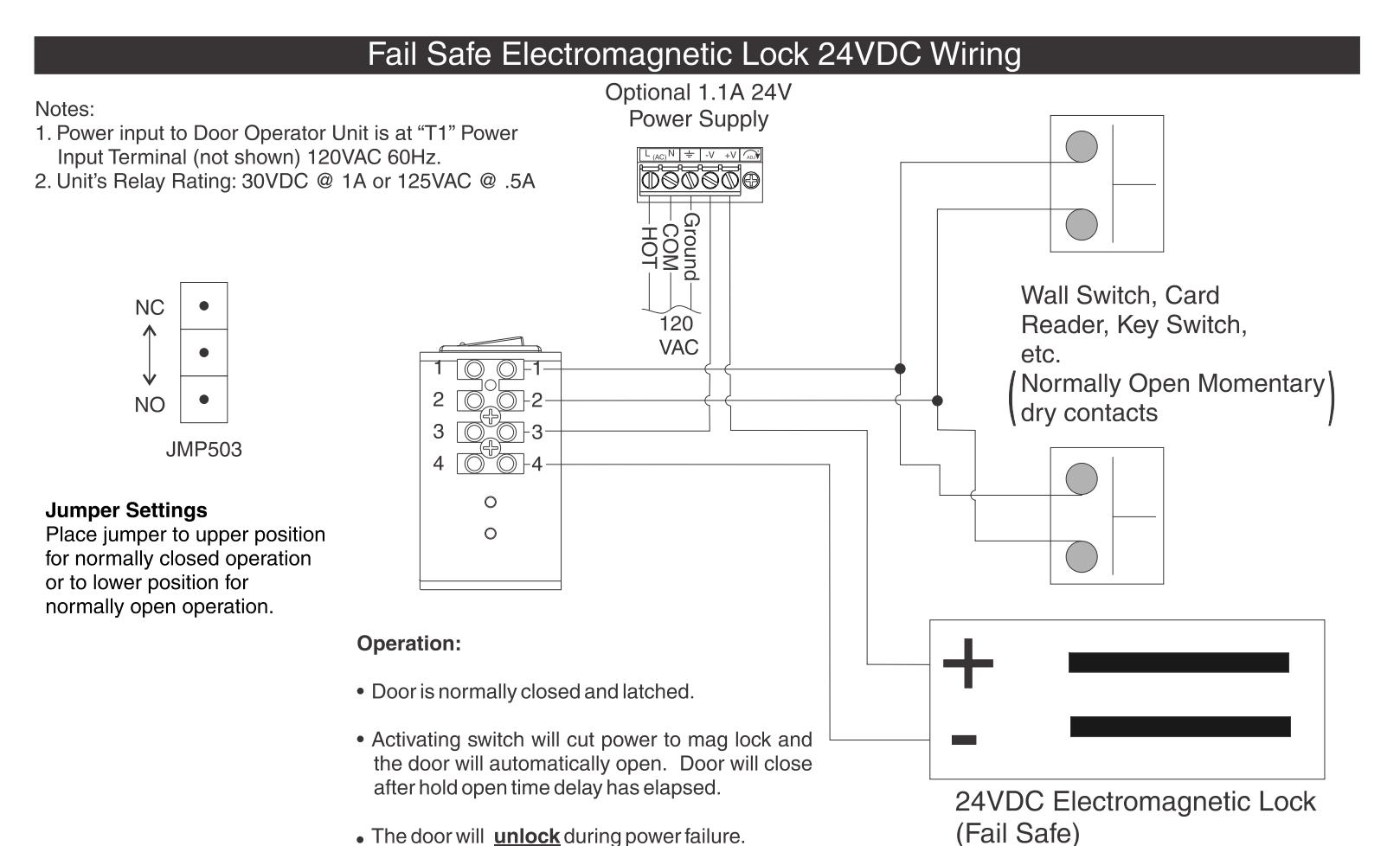
Fail Secure / Fail Safe Electric Strike Wiring
Notes:
- 1. Power input to Door Operator Unit is at "T1" Power Input Terminal (not shown) 120VAC 60Hz.
- 2. Unit's Relay Rating for strike interface: 30VDC @ 1A or 125VAC @ .5A
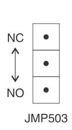
Jumper Settings
Place jumper to upper position for normally closed operation or to lower position for normally open operation.
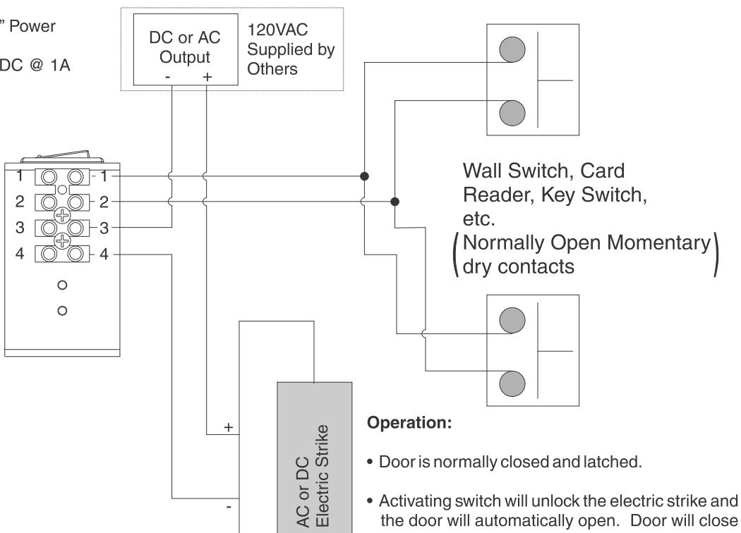
- the door will automatically open. Door will close after hold open time delay has elapsed.
- For Fail Secure Strike The door will remain locked during power failure.
- For Fail Safe Strike The door will remain unlocked during power failure.
Troubleshooting
| Fault | Possible reasons why | Remedies/Explanations |
|---|---|---|
| The door does not open | Control switch is set to OFF position | Change the setting of the ON/OFF switch |
| - The motor does not start | Circuit breaker is set to OFF position | Reset circuit breaker to the ON position |
| Electrical power is missing | Check the electrical power switch | |
| Activation unit does not function | Jump activation input | |
| - The motor starts | Motor is driving in wrong direction | Flip Door Mounting Dip Switch to other direction |
| Something jammed beneath the door | Remove object | |
| Arm has come loose | Re-time and re-install arm. | |
| The door does not close | Spring tension too low | Increase spring tension per preceding instructions |
| Arm has come loose | Re-time and re-install arm. | |
| Something jammed beneath the door | Remove object |
Arrow Lock & Door Hardware
P.O. Box 3075 Salem, VA 24153 Phone USA: 800-839-3157 • Fax 800-421-6615
RROW LOCK & DOOR HARDWARE ASSA ABLOY
Arrow Lock® is a registered trademark of ASSA ABLOY. Copyright © 2010 Arrow Lock, Inc., an ASSA ABLOY Group company. All rights reserved. Reproduction in whole or in part without the express written permission of Arrow Lock is prohibited.
80-9359-0001-040 (10-10) Page 11
This page intentionally left blank.