Alarm_Lock_DL2800_Programming_Instructions
Open the original PDF document
View PDF

345 Bayview Avenue, Amityville, New York 11701 For Sales and Repairs 1-800-ALA-LOCK
For Technical Service 1-800-645-9440 or visit us at http://tech.napcosecurity.com/ (Note: Technical Service is for security professionals only) Publicly traded on NASDAQ Symbol: NSSC
© ALARM LOCK 2017
Trilogy DL2800 Programming Instructions
OI246DLF 03/17
DL2800 Trilogy Series Standalone Access Control System
DL2800 SERIES LOCK
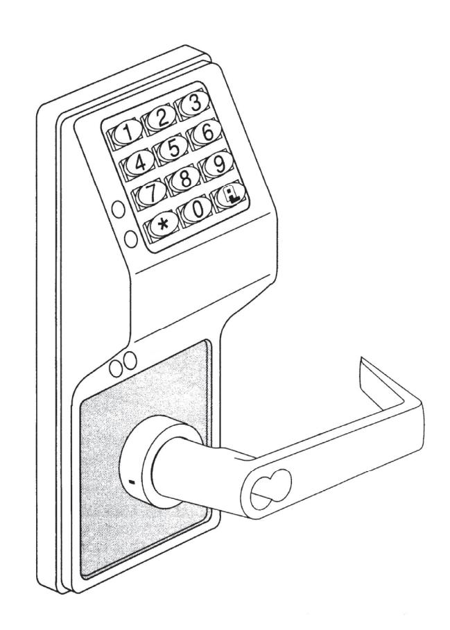
THE ALARM LOCK TRILOGY DL-SERIES STAND-ALONE ACCESS CONTROL SYSTEM IS A SERIES OF STATE-OF-THE-ART MICROPROCESSOR-BASED PROGRAMMABLE KEYPAD-ENTRY SECURITY LOCKS.
DL2800
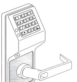
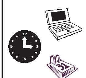
Features a real-time clock/calendar that automatically adjusts for Daylight Saving Time and allows for automated programming of events. Features three methods of programming:
- (1) All features can be programmed manually through the keypad;
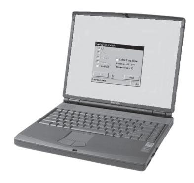
- (2) You can transfer programming instructions directly from your laptop or desktop PC using DL Windows software and a special AL-PCI cable; and
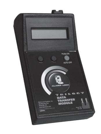
- (3) Data can be transferred from your PC to your DL lock via the AL DTM handheld Data Transfer Module .
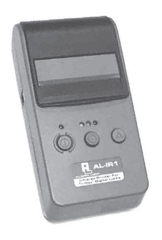
In addition, data can be retrieved from the lock in one of three ways (1) through an infrared printer; (2) directly from the lock to the PC; or (3) through an AL-DTM to your PC.
Table of Contents
| DL2800 Lock Features 3 | Product Communication Examples 12 |
|---|---|
| Supported Products 4 | Programming FunctionsOverview 13 |
| Lock Design Overview 5 | Programming Functions 14-26 |
| Quick Start 6 | Groups and Scheduled Group 1 Examples 27-28 |
| Terminology Used in this Manual 7 | Programming Record Sheet 29 |
| Conventions Used in this Manual 8 | User Code Record Sheet 30 |
| Programming Levels 9 | Schedule Record Sheet 31 |
| Wiring, Power Up & Battery Replacement 10 | Glossary 32-33 |
| LED and Sounder Indicators 11 | ALARM LOCK LIMITED WARRANTY 36 |
DL2800 Lock Features


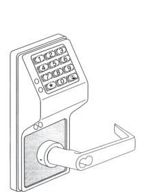
User Features
- 200 Users
- Pre-defined Administration User Levels including Master , Manager and Supervisor User Codes (see page 9)
- User Code Lengths from 3-6 digits
- Service Code ("One-Time-Only" Code) (see page 8)
- User Lockout Mode (see page 15, Function 6)
- Users Assignable to 4 Groups (see page 17)
Lock Features
- Metal Key Override
- Keypad Lockout (see page 22, Functions 60-61)
- Non-Volatile (Fixed) Memory
- Real-Time Clock adjustable to within 1 second (see page 19, Functions 43-44)
- Visual and Audible Keypad Feedback (see page 11)
- Battery Status Monitor (see page 10-11)
Scheduling
- 150 Scheduled Events (see page 24)
- Automated Unlock/Lock
- Enable/Disable Users (see page 14, Function 3)
- Enable/Disable Groups (see page 16)
- Four "Quick Schedules" (contains 4 most common schedules) (see page 25)
- Real-time clock and calendar (see page 18)
- Programmable Timeout Functions (see page 17)
User Access Methods
- Keypad Entered User Codes (see page 14)
- Metal Key Override
Keypad and Computer Programming
All programming may be performed manually from the keypad, or from a PC using Alarm Lock's DL-Windows Software (see page 8. "What is DL-Windows?")
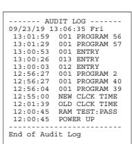
Audit Trail
- 1000 Event Capacity
- Entries Logged with Time and Date
- Critical Programming Events Logged
- Printable using the AL-IR1 Hand-Held Printer (see page 21, Function 55)
- Transferable using Alarm Lock's DL-Windows software (see page 21, Function 58)
- Transferable to AL-DTM
AL-DTM Data Transfer Module
Use Alarm Lock's AL-DTM to easily transfer program data between locks and a PC running DL-WINDOWS software. Easily transfer Audit Trail from multiple locks and then view or print each Audit Trail from a computer.
Supported Products
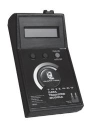
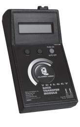
Data Transfer Module ( AL-DTM )
An AL-DTM can be used to transfer Lock Programs (and other data) between DL-Windows and locks. When computers cannot be transported or when electrical power is not available, the hand-held AL-DTM device acts as a go-between--it allows the transfer of lock data from the computer (through the AL-DTM ) and to the lock, or in reverse (from the lock through the AL-DTM back to the computer). Use of the older AL-DTM model 1 is not recommended. Note: The latest model, the AL-DTM-III, is supported in DL-Windows version 3.5.1 or later.
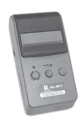
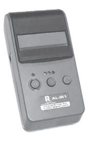
Infrared Printer (AL-IR1)
An AL-IR1 printer is used to print Audit Trails and User Code (PIN) lists (where used) without the need for a PC. Its infrared reader means no cable connection is needed (not for use with Networx™ series locks or devices).
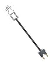
AL-PCI2 Cable
The AL-PCI2 cable is required to communicate between your computer's RS-232 serial communications port and the AL-DTM3 or lock. One end of the AL-PCI2 cable is designed to be plugged into a DB-9 male 9-pin serial COM port. If your computer has a 25-pin COM port only, a 25-pin to 9-pin adapter must be used. The other end of the AL-PCI2 cable features a 2-pin banana plug connector which is polarity sensitive (the TAB marked "GND" must be plugged into the lock's black left terminal). Note: The AL-PCI2 can be used with an MX1130 adapter (see next page).
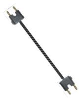
Double-ended Mini Banana Plug Connector (part MX942)
After you create your lock programming in DL-Windows and transfer the DL-Windows programming to an AL-DTM3 , transfer the programming from the AL-DTM3 to your lock via a double-ended mini banana plug.
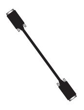
DB9 to DB9 Serial Cable
Enroll User Codes quickly into DL-Windows, then transfer this new User Code data from DL-Windows to the AL-PRE2 via this 9-pin DB9 to DB9 serial cable. Once the data is in the AL-PRE , you can transfer the data to the lock via the Double-ended Mini Banana Plug Connector (see above), thus avoiding the need to use an AL-PCI2 cable for this process.
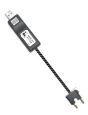
ALPCI2-U (USB) Cable
The ALPCI2-U cable is required to communicate between your computer's USB communications port and the AL-DTM3 or lock. One end of the ALPCI2-U cable is plugged into a computer USB port, and the other end features a 2-pin banana plug connector which is polarity sensitive (the TAB marked " GND " must be plugged into the lock's black left terminal). Note: All references to communications in this manual will refer to the ALPCI2-U cable, but if you do not have an ALPCI2-U cable, you can still use the older AL-PCI2 cable described above. Note: The ALPCI2-U will eventually replace the older AL-PCI2 (see above), therefore the MX1130 adapter (see below) will no longer be needed.
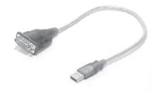
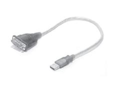
USB to RS-232 Cable
If your computer does not have a serial COM port (DB-9 male) available, you can plug your AL-PCI2 cable into a special USB to RS-232 cable. Order part MX1130 for the USB to RS-232 cable only, or ALPCI2-U for both the USB to RS-232 cable and an AL-PCI2 cable.
Lock Design Overview
Why Use User Codes?
With ordinary door locks, the need to make physical copies of metal keys and distributing them can be a huge organizational and financial task -- and what will you do if someone causes a security breach by accidentally losing their key?
The answer lies in the advantage of firmware . The firmware inside your DL2800 can be programmed (and re-programmed again and again) to suit your changing requirements. No more metal keys to distribute...instead, distribute User Codes -- and delete them from the firmware when needed. A User Code is the firmware equivalent of a metal key--it is a series of numeric button presses at the DL2800 keypad to allow (for example) passage through the door.
Preparing to Program your Lock
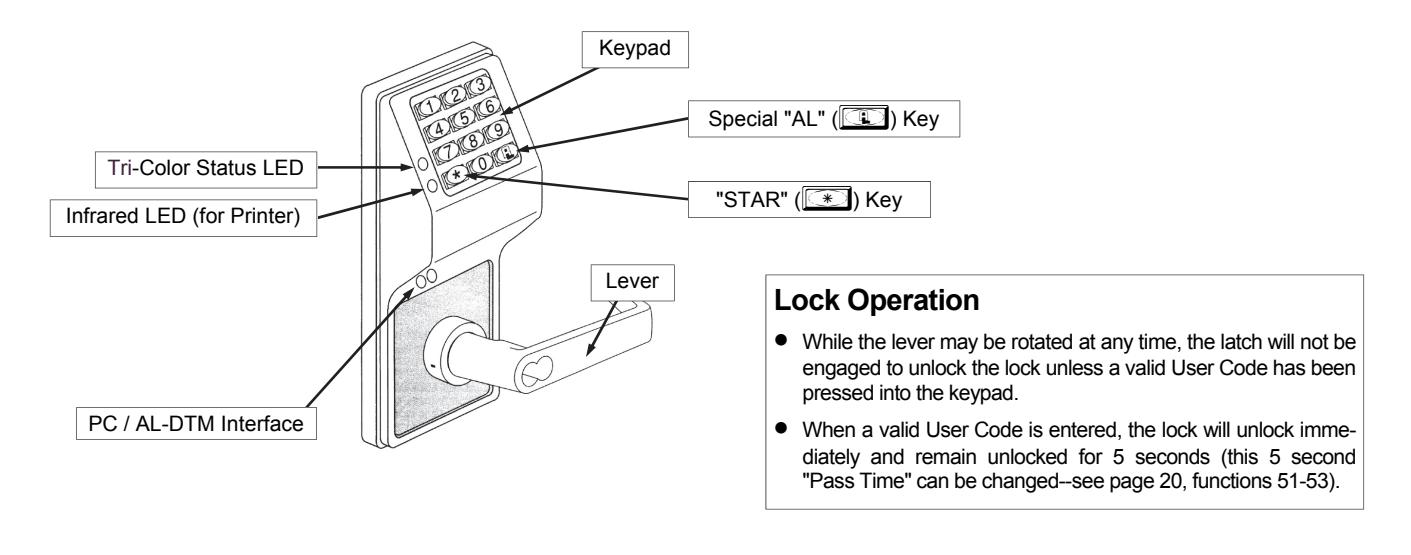
The DL2800 lock keypad contains 12 buttons, numbers 1 through 9 plus zero, a star button ( : ) and a special "AL" button ( ; ). You can either use these 12 buttons to program your lock --or-- you can program your lock using a computer program called DL-Windows . DL-Windows is not required , but it makes programming faster and easier. This guide will show you how to program your lock manually using only the keypad (without DL-Windows). For more information about DL-Windows, see User Guide OI237.
Programming your lock begins after you unpack it from the box -- there is a specific procedure outlined on page 6 ("Quick Start") in which you "wake up" the lock to prepare it for use. To begin programming the lock, you must first enter something called "Program Mode".
What is Program Mode?
The firmware inside the lock has two "modes": "Normal Mode" and "Program Mode". When you want to make changes to the lock program (to add User Codes for example), you enter "Program Mode". When you finish programming and wish to put the lock into use, exit "Program Mode" to enter "Normal Mode".
You enter Program Mode using the keypad--by pressing the Master Code that was set at the factory. The Master Code is basically a secret passcode that allows you to enter Program Mode. But since all locks are identical and leave the factory with the same Master Code, the factory Master Code is therefore not very secret--and should be changed to your own personal Master Code. This is to ensure that only YOU can enter Program Mode and make changes to the lock programming.
Once the new Master Code is set , then you can continue with the Quick Start procedure and set the weekday, date and time. After this, you can start entering User Codes for people to use. All changes to the lock are organized by their "Function Number". Want to change the date? Use Function Number 38. Want to add a User Code? Use Function Number 2. There are 99 Functions in total, some that you will use often, and others that you may never need to use.
Notice that when you program your lock, programming tends to follow a consistent 5-step pattern: (1) Enter Program Mode (2) Press ; followed by the Function Number (3) Press ; and enter data (4) Press : to end (5) Exit Program Mode.
Turn to page 7 and learn about the special terminology used with your lock. The Quick Start procedure (on page 6) will help you get up and running quickly.
Quick Start
First Time Start Up
IMPORTANT: Failure to follow this exact procedure can result in erratic lock behavior.
The DL2800 lock uses five (5) AA-size 1.5 volt alkaline batteries. Remove the back cover, install batteries into the battery pack. Connect the battery pack plugs and the lock will beep 3 times. To load the default program press any key within 5 seconds, the lock will beep slowly while the default values are loaded and beep rapidly upon completion.
| Enter Program Mode and Change Factory Master Code |
|---|
| 1. Press the default Master Code: 123456. |
| 2. Wait for the green light and press ; until multiple beeps are heard. You are now in Program Mode. |
|
(Note: The lock will beep every 6 seconds as a reminder that you are in Program Mode).
3. Enter a new personal 6-digit Master Code number by pressing the following keys: ;1; [new Master Code] ; [new Master Code] : (the second set of digits must be exactly the same). |
|
(For example, if you want your new Master Code to be "664433". Press:
;1 ;664433 ; 664433 :). |
|
Now that the Master Code has been changed, there is no need to change it again (unless you want to). Since you
are still in Program Mode, you can now proceed directly below and program various functions. Note: Programming any Function, such as setting the time, follows a consistent 5-step pattern: (1) Enter Program Mode (2) Press ; [Function #] |
| (3) Press ; and enter data (4) Press : to end (5) Exit Program Mode (if desired). |
|
Set the Weekday
1. Enter Program Mode (if not in already). 2. Press ;40; [number of weekday] :. (Use 1= Sunday, 7 = Saturday). (For example - Friday - press ;40 ;6 :). |
| Set the Date |
|
1. Enter Program Mode (if not in already).
2. Press ;38; [MMDDYY] :. (For example - May 10, 2002 - press ;38 ;051002:). |
|
Set the Time
1. Enter Program Mode (if not in already. If you just finished the above procedure, you are still in Program Mode). 2. Press ;39; [HHMM] :. (Use 24-hour military (HHMM) format, where PM adds 12 hours). (For example - 2:30pm - press ;39 ;1430:). |
| Enter User Codes |
|
1. Enter Program Mode (if not in already).
2. Press ;2; [User Number] ; [User Code] :. |
|
(For example, John Smith is designated as User 21. You want him to use the User Code of "232323" to unlock the
lock. Program the lock by pressing: ;2 ;21 ;232323 :). |
| 3. Repeat step 2 for each new User. |
|
Exit Program Mode
Hold Down any key for 3 seconds. Program Mode exit is confirmed by several beeps. You are now in "normal" operation. |
|
Re-enter Program Mode
If you wish to re-enter Program Mode, key-in your new 6-digit Master Code, and press ;. |
|
You are now ready to mount and install your DL2800 series lock and give out your User Codes. Before installation, it is suggest
ed you test and verify that all User Codes entered are active. Use the IR1 infrared printer (available separately) to print your own Audit Trail logs and User Codes list. |
Terminology Used in this Manual
The Lock Program
A Lock Program is the firmware stored within the lock's circuitry and contains the instructions that the lock uses to perform its various functions. You can use the keypad to change the Lock Program. You can also use DL-Windows (defined below) to create a Lock Program on your computer, and then transfer and store the Program in the firmware. The Lock Program is essentially a computer database file that maintains feature settings, schedules, Audit Trails, etc. Using DL-Windows, a Lock Program (called a "Lock Profile" in DL-Windows) can be created with default information, edited on your PC, and then sent to (and even received from) the lock.
The Lock Program consists of 4 areas: User Codes , Functions , Time Zones , and Schedules , all defined below:
User Codes
Also called "User Access Codes", "Passcode numbers" or "PIN Number Codes", a User Code is a 3 to 6 digit number the User enters into the keypad (using the keypad buttons) to unlock the lock. The DL2800 can store hundreds of different User Codes in its Lock Program, and the Lock Program is stored in the lock circuitry awaiting the Users to key in their individual User Codes. Each User Code is associated with a User Number , defined below.
The User
A User is defined as a person who is authorized to operate or perform programming changes to the Lock Program. The DL2800 lock can hold hundreds of "Users" (in the form of User Codes ) in its Lock Program, and each User possesses a predefined level of authority--a Programming Level --as to their ability to use or make changes to the Lock Program. Some Users may be able to unlock the lock only; others may also be able to make changes to the Lock Program.
User Numbers
( User Number = Location Number = User Location = Slot ) User Numbers are used and are significant within each individual lock only. The DL2800 Series locks can hold up to 200 User Numbers in its Lock Program, which can be thought of as simply a numbered list from 1 through 200 (with number 1 at the top). Each User Number can be programmed with a User Code. In addition, each User Number possesses a pre-defined level of authority--a Programming Level --as to the User's ability make changes to the Lock Program. Where a User is located in this list--their User Location --is a commonly used description of their User Number. Because of their similarities, the terms User Number , User Location and Location Number can be used interchangeably. In some DL-Windows screens, the word "Slot" is also used. They all mean the same thing.
Since User Numbers are fixed, knowing the location of a User Number will specify its associated Programming Level, and will in turn indicate a User's programming abilities (if any). For example, User Number 1 is always the Master, who can perform all programming tasks. Lower down the list, User Number 189 is a Basic User and although this User is assigned a User Code to unlock the lock, because they are a "Basic User" they are unable to perform any programming changes.
Programming Functions
Your lock is designed to support many different features that
can be programmed to suit each installation. Using the keypad (or DL-Windows software), authorized Users can activate these features and make other changes to the Lock Program. Each of these features is called a Programming Function. In addition, each Function possesses its own pre-defined Programming Level to access that Function. Each User must possess a Programming Level EQUAL to the Programming Level assigned to the Function in order to access that Function. When programming via the keypad, see page 13 for a list of all Functions 1 through 99. For example, you can enable Daylight Saving Time via Function number 41. Each Programming Function is described on pages 14-26.
Programming Levels
The Programming Level defines which Programming Functions a User is allowed to perform. Each User Number is associated with a defined level of ability--a Programming Level --as to which Functions the assigned User can access. The highest level--Master--allows access to ALL Functions.
In addition, each Function (see pages 14-26) has its own fixed Programming Level .
A User must possess a Programming Level equal to the Programming Level of the Function in order to access that Function.
Programming Levels can have a value of "1", "2", "3", "4" or "M". Note: Having a Programming Level of "3" does not allow access to Functions with Programming Levels of 1, 2 or 4.
The following defaults apply when adding User Codes via Programming Function 2:
Master: The highest level User, and always associated with User Number 1 and its Master Code only. Master is always enabled and can program ALL Functions. (Abbreviated as the Programming Level = " M ").
Manager: Always associated with User Numbers 2-6. Can program all Functions except Functions relating to lock configuration. (Abbreviated as Programming Level = " 1 ", " 2 " or " 3 ").
Supervisor: Always associated with User Numbers 7-11. Can only program Functions relating to certain day to day operations. (Abbreviated as Programming Level = " 1 " or " 2 ").
Basic Users: Always associated with User Numbers 12 through 200. When adding User Codes for Basic Users via Programming Function 2, Programming Levels are not assigned by default. Note: Programming Levels for Users 2- 200 can be assigned via Function 8. For Users 299 and 300, see below for entries.
See chart on page 9 for a summary.
Groups
It is convenient for large numbers of similar Users to be grouped together. By placing Users into Groups (assigning them to a specific range of User Numbers), large numbers of Users can be controlled all at once rather than individually- saving time and effort. Groups are controlled via schedules, and a typical example involves enabling or disabling a Group at a certain time. The DL2800 lock has factory-programmed Default Group Associations that are specified in the table on page 9. For example, if you wish to add a User to Group 1, assign this User to a User Number between 51 and 100. These De-
Terminology Used in this Manual (cont'd)
fault Group Associations can be changed if needed to allow Groups larger than the default quantity of 50 (by using keypad Function 35). (See page 25 for some Group function examples).
Schedules and TimeZones
You can use the keypad to add simple "Schedules" to your lock. Schedules are events (recorded lock activities) that are assigned to occur automatically at specific times. For example, you can program the lock to allow Group 1 Users access ONLY on Wednesdays.
DL-Windows multiplies your flexibility, allowing the creation of many different combinations of Scheduled events to suit the needs of your various installations. For example, you can program the lock to allow Group 1 Users access ONLY during specific business hours (unlock at 9AM, lock at noon for lunch, unlock at 1PM, and lock again at 5PM--every weekday).
In addition, DL-Windows makes Schedule creation much easier. Use the Schedule - TimeZone screen to first create an individual block of time called a "TimeZone" (for example, "9AM to noon weekdays"). A TimeZone is then linked to an event to make a Schedule (for example, "unlock between 9AM and noon weekdays"). To make Scheduling easier, DL-Windows allows TimeZones to be created, named and saved for the future, to be easily assigned to different events and added to multiple locks as needed. When finished, you can view (in DL-Windows) your schedule in the Schedule View screen.
Users 299 & 300
User Codes added to locations 299 and 300 have special abilities, as follows:
User 299: AL-DTM Code
This is the only User Code that will initiate data transfer with the AL-DTM--and without allowing the lock to unlock (the User Code for User Number 299 does NOT allow access/ unlocking). An AL-PCI cable and an AL-DTM (preprogrammed by a computer with DL-Windows) are required.
User 300: One-Time Only Service Code
This is a one-time-only service User Code designed to be used for access by temporary workers. When enabled, entering User Code 300 into the keypad will allow the DL2800 lock to unlock only once (re-entering User Code 300 will not operate). User Number 300 is enabled by Function 9. ( Note: Function 9 can only be enabled by Users with a Program Authority Level of 2).
User Code 300 can also be used for Guard Tour duties: The User 300 code can be used to log the movement of a security guard as he or she makes rounds from one assigned guard tour station to the next. The entering of this code provides precise verification and accountability of a guard's movement by logging the location with a time and date stamp in the Audit Trail.
DL-Windows
DL-Windows is a computer program that allows you to program your ALARM LOCK Security Lock. You do not need DL-Windows to program your lock, but it makes programming much faster and easier. With DL-Windows, you can quickly create Lock Programs, add multiple Users, retrieve event logs, and create Schedules. The benefit of DL-Windows is that it allows you to set up all lock programming in advance (on your computer), and then later transfer the information into the installed locks at your convenience.
Conventions Used in this Manual
Required Programming Level
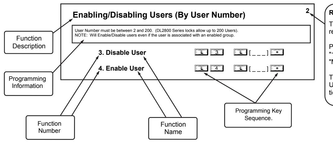
This is the Programming Level required to access the Function.
Possible Programming Levels are "1", "2", "3", "4" and "M", where "M" = Master Code.
The Programming Level of the User must be equal to the Function that is to be accessed.
General Program Mode Information
If a wrong key is pressed during code entry, hold any key continuously until the error sound is heard (7 short beeps), this will clear the entry. Re-enter the key sequence again.
All program sequences are followed by the : key; 2 short beeps indicate a successful program sequence.
Programming Levels
The Programming Level defines which Programming Functions a User is allowed to perform. Each User Number is associated with a defined level of ability--a Programming Level - as to which Functions the assigned User can access. The highest level--Master--allows access to ALL Functions.
In addition, each Function (see pages 14-26) has its own fixed Programming Level .
A User must possess a Programming Level equal to the Programming Level of the Function in order to access that Function.
Programming Levels can have a value of "1", "2", "3", "4" or "M". Note: Having a Programming Level of "3" does not allow access to Functions with Programming Levels of 1, 2 or 4.
The following defaults apply when adding User Codes via Programming Function 2:
Master: The highest level User, and always associated with User Number 1 and its Master Code only. Master is always enabled and can program ALL Functions. (Abbreviated as the Programming Level = " M ").
Manager: Always associated with User Numbers 2-6. Can program all Functions except Functions relating to lock configuration. (Abbreviated as Programming Level = " 1 ", " 2 " or " 3 ").
Supervisor: Always associated with User Numbers 7-11. Can only program Functions relating to certain day to day operations. (Abbreviated as Programming Level = " 1 " or " 2 ").
Basic Users: Always associated with User Numbers 12 through 200. When adding User Codes for Basic Users via Programming Function 2, Programming Levels are not assigned by default. Note: Programming Levels for Users 2-200 can be assigned via Function 8.
|
Users programmed with Function 2 will default to a Group
Association and a Programming Level Ability as follows: |
|||
|---|---|---|---|
| USER TYPE |
DEFAULT
USER NUMBER GROUP ASSOCIATION |
DEFAULT
PROGRAMMING LEVEL |
|
| Master Code | 1 | none | M, 4, 3, 2, 1 |
| Manager Codes | 2 - 6 | none | 3, 2, 1 |
| Supervisor | 7 - 11 | none | 2, 1 |
| Basic User Codes | 12 - 50 | none | none |
| Basic User Codes Group 1 | 51 - 100 | 1 | none |
| Basic User Codes Group 2 | 101 - 150 | 2 | none |
| Basic User Codes Group 3 | 151 - 200 | 3 | none |
| Initiate DTM (Non-Pass Code) | 299 | none | none |
| Service Code | 300 | none | none |
NOTE:
User 299 is a Non-Pass Code. This is the only code that will initiate data transfer with the AL-DTM.
Wiring, Power Up & Battery Replacement
WIRING
See the Installation Manual for more information.
Batteries:
Use only AA-size 1.5 volt alkaline batteries. With average use, batteries last about 5 years.
Terminals (Standard Models Only)
Red & Black Wires (Operation without Batteries) - Optional 7.5VDC voltage for operation without batteries. White & White Wires (Remote Input) - Wire a normally open contact to terminals 3 & 4. Momentarily close to unlock the DL2800 to allow person to pass through door. NOTE: Remote Input is enabled from the factory. PC Interface - Connect to serial port on PC using AL-PCI interface cable.
Wire Leads for DL2800WP (Waterproof) Models
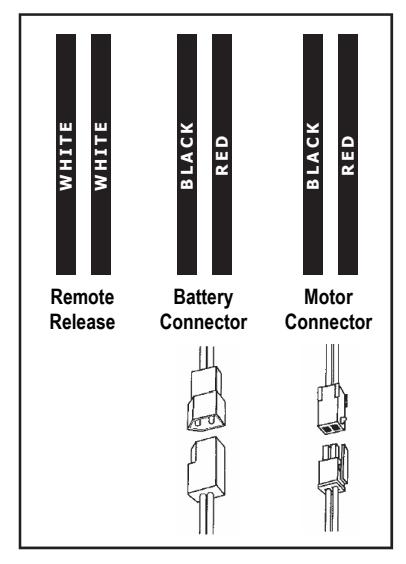
Note: On all WP waterproof models, use the provided dielectric grease on the battery connectors to ensure a waterproof connection.
POWER DOWN --RETAIN LOCK PROGRAMMING
- When applying power to the lock for the first time , stop here and follow the procedure outlined in "QUICK START" on page 6.
- When power is re-applied to a lock that was already operational and you wish to retain the lock programming (such as when transferring the lock from an old door to a replacement door), proceed as follows:
- 1. Unplug battery pack.
- 2. Do not to touch the keypad keys (an accidental press of a key may sometimes result only in a need to reset the clock; User Codes will be retained).
- 3. Re-connect battery pack. Lock MUST sound 3 short beeps (otherwise, start again at step 1).
- 4. Do not press any keys for 10 seconds .
- 5. After the 10 second period the LED will flash red 6 times and 6 beeps will sound. The lock is now ready
for use (program is loaded from fixed memory). Note: If Audit Trail and/or clock settings are lost, re-set the clock using functions 38, 39 and 40.
ERASE ALL PROGRAMMING
- The "out of box" factory default will be loaded:
- 1. Unplug battery pack.
- 2. Press and hold ; for 30 seconds to ensure the lock circuitry is fully discharged.
- 3. Re-connect battery pack. Lock MUST sound 3 short beeps (otherwise, start again at step 1).
- 4. Press and hold ; within 5 seconds after hearing the 3 short beeps.
- 5. A series of slow beeps will sound to signify that all settings and programming are being erased. When finished, the lock will be ready for use.
Note: All lock programming can also be erased without the need to disconnect the batteries by using Function 99.
BATTERY REPLACEMENT
If applying power to the lock for the first time , stop here and follow the procedure outlined in "QUICK START" on page 6.
When the batteries are weak and a valid code is entered, the light amber LED lights and the sounder sounds for 4 seconds.
- For models with a replacable battery pack, use five (5) AA-size 1.5 volt alkaline batteries.
- For models with a sealed battery pack, contact your Alarm Lock dealer for a replacement battery pack. Always replace weak batteries as soon as possible.
CAUTION: Do not press any keys while batteries are disconnected or you may erase the real-time clock settings. Pressing any key will remove the voltage that is required to keep the system clock and Audit Trail in memory. Before performing the following steps, read through them first to familiarize yourself with these operations.
- 1. At the back of the lock, remove the screw at the bottom of the lock housing and remove the cover.
-
2. Pull out the battery pack and quickly replace all 5 batteries - within 2 minutes. For models with the sealed battery pack, simply unplug the old battery pack and plug in the new battery pack.
- If you DO NOT hear the 3 beeps when power is re-applied, all programming and settings have been retained, and the lock is ready for use. Go to step 5.
- If you DO hear 3 beeps when power is re-applied, do not press any keys for 15 seconds . After the 15 second period, the LED will flash red 6 times and 6 beeps will sound. Reset the clock using functions 38, 39 and 40.
- 3. Replace the cover and tighten the screw.
LED and Sounder Indicators
The DL Series locks provide visual and audible keypad feedback. With a fully charged battery, the LED and sounder feedback is as follows:
| ACTIVITY | LED | SOUNDER | COMMENTS |
|---|---|---|---|
| Keypress | 1 Red Flash | 1 Beep | Normal Operation |
| Access Granted or Remote Input | 2 Green Flashes | 2 Beeps |
For Remote Input, wire a normally
open contact to these two white wires. Momentarily close to un lock. See page 10 for more infor mation. |
| Valid Code |
1 Momentary Green
Flash |
||
| Invalid Code | 6 Red Flashes | 6 Beeps | Re-enter User Code |
| Successful Program Entry | 1+2 Green Flashes | 1+2 Beeps | When in Program Mode |
| Unsuccessful Program Entry | 7 Red Flashes | 7 Beeps | When in Program Mode |
| Enter Program Mode |
2 Yellow & 1 Green
Flash |
||
| Exit Program Mode |
1 Red, 2 Green,
1 Red Flashes |
2 Groups of 5
Beeps |
|
| Valid but Disabled Code |
1 Red, 1 Green, 4 Red
Flashes |
1 long, 5 short
Beeps |
Code exists in memory,
but disabled |
|
Low Battery upon User Code
Entry or upon closing of Remote Release switch |
Yellow Flash during key
presses |
Steady 4-Second
Tone |
LED and sounder indications occur
only when a valid code is entered. See page 10 before changing batteries |
| Button Press |
Continuous Series
of Beeps |
System Fault. Ensure batteries
are fresh |
Product Communication Examples

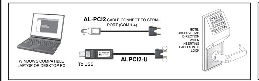
If your computer does not have a serial COM port (DB-9 male) available, you can plug your AL-PCI2 cable into a special USB to RS-232 cable. Order part MX1130 for the USB to RS-232 cable only, or ALPCI2-U for both the USB to RS-232 cable and an AL-PCI2 cable.
Create the Lock Profile in DL-Windows on your computer, then transfer the data from the computer directly to the lock via an AL-PCI2 cable. When no COM port exists, use a USB to RS-232 cable (see above). Alternatively, you can use an ALPCI2-U (USB) cable in place of the older AL-PCI2 cable.
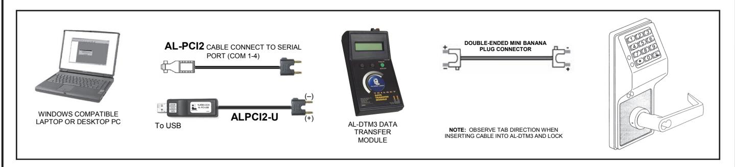
Create the Lock Profile in DL-Windows and transfer the data from DL-Windows to an AL-DTM3 (via an AL-PCI2 or ALPCI2-U cable), then transfer the data from the AL-DTM3 to the lock via a Double-ended Mini Banana Plug Connector). The hand-held AL-DTM3 is useful because you do not have to transport (or find electricity for) your computer. Data can also flow in reverse, from the lock, through the AL-DTM3, back to the computer for examination.
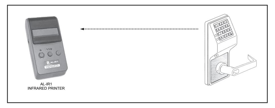
Use the AL-IR1 Infrared printer to print your lock's audit trail (Event Log), User Code (PIN) list, clock settings and software version. No cable required.
NOTE:
The AL-PCI cable is designed to be used on a 9 pin serial COM port. If your computer has a 25 pin COM port, a 25 pin to 9 pin adapter must be used. Warning: Polarity MUST be observed when connecting cables to the lock. The tab (–) must plug into the negative (black) hole.
Programming Functions--Overview
|
FUNCTION
NUMBER |
DESCRIPTION |
PAGE
NUMBER |
|---|---|---|
| Function 1 | New Master Code | 14 |
| Function 2 | Add/Delete/Change User Codes 2 -200 | 14 |
| Function 3 | Disabling Users (By User Number) | 14 |
| Function 4 | Enabling Users (By User Number) | 14 |
| Function 5 | User Enable with Timeout | 15 |
| Function 6 | Enable Total User Lockout Mode | 15 |
| Function 7 | Disable Total User Lockout Mode | 15 |
| Function 8 |
Change User Programming Level
Ability |
15 |
| Function 9 | Enable User 300 (Service Code) | 15 |
| Function 10 | Erase All Users Except the Master Code (User 1) | 15 |
| Function 11 | Reserved | 15 |
| Function 12 | Clear All Schedules and Timeout Functions | 16 |
| Function 13 | Clear All Timeout Functions | 16 |
| Function 14 - 17 | Group 1-4 Disable | 16 |
| Function 18 | Disable All Groups | 16 |
| Function 19 - 22 | Group 1-4 Enable | 16 |
| Function 23 | Enable All Groups | 16 |
| Function 24 | Reserved | 16 |
| Function 25 - 28 | Timed Disable Groups 1-4 | 17 |
| Function 29 | Timed Disable All Groups | 17 |
| Function 30 - 33 | Timed Enable Groups 1-4 | 17 |
| Function 34 | Timed Enable All Groups | 17 |
| Function 35 | Group Add/Delete Association | 17 |
| Function 36 - 37 | Reserved | 17 |
| Function 38 | Set Date | 18 |
| Function 39 | Set Time | 18 |
| Function 40 | Set Weekday | 18 |
| Function 41 | Daylight Saving Time Start Date | 18 |
| Function 42 | Daylight Saving Time End Date | 18 |
| Function 43 | Speed Up Clock | 19 |
| Function 44 | Slow Down Clock | 19 |
| Function 45 | Enable Passage Mode | 19 |
| Function 46 | Disable Passage Mode | 19 |
| Function 47 | Timed Passage Mode | 19 |
| Function 48 | Enable Permanent Passage Mode | 20 |
| Function 49 |
Disable Permanent Passage
Mode |
20 |
| Function 50 |
Return Lock to Normal Passage
Mode Schedule |
20 |
| Function 51 | Set Pass Time 3 to 5 Seconds | 20 |
|
FUNCTION
NUMBER |
DESCRIPTION |
PAGE
NUMBER |
|---|---|---|
| Function 52 | Set Pass Time to 10 Seconds | 20 |
| Function 53 | Set Pass Time to 15 Seconds | 20 |
| Function 54 | Reserved | 20 |
| Function 55 | Print Audit Trail | 21 |
| Function 56 | Print User Code List | 21 |
| Function 57 | Print Clock Settings and Software Version | 21 |
| Function 58 | Upload/Download PC Data | 21 |
| Function 59 | Reserved | 22 |
| Function 60 |
Number of Attempts Before Lock-
out |
22 |
| Function 61 | Set the Attempts Lockout Time | 22 |
| Function 62 - 63 | Reserved | 22 |
| Function 64 | Disable Remote Input | 22 |
| Function 65 | Enable Remote Input | 22 |
| Function 66 | Reserved | 22 |
| Function 67 | Reserved | 23 |
| Function 68 | Reserved | 23 |
| Function 69 | Enable Enter Key | 23 |
| Function 70 | Disable Enter Key | 23 |
| Function 71 | Reserved | 23 |
| Function 72 | Schedule Enable Passage Mode (Unlock) | 24 |
| Function 73 | Schedule Disable Passage Mode (Lock) | 24 |
| Function 74 - 77 | Schedule Enable Groups 1-4 | 24 |
| Function 78 | Schedule Enable All Groups | 24 |
| Function 79 - 82 | Schedule Disable Groups 1-4 | 24 |
| Function 83 | Schedule Disable All Groups | 24 |
| Function 84 - 87 | Quick Schedules - Enable Group | 25 |
| Function 88 |
Passage Mode
(Open Time Window) |
25 |
| Function 89 |
Passage Mode
(Close Time Window) |
25 |
| Function 90 | Reserved | 26 |
| Function 91 | Reserved | 26 |
| Function 92 |
Enable Group 4
(Open Time Window) |
26 |
| Function 93 |
Enable Group 4
(Close Time Window) |
26 |
| Function 94 - 98 | Reserved | 26 |
| Function 99 | Clear All Lock Programming | 26 |
Programming Functions
USERS
|
1. New Master Code
(User Number 1) |
; 1 |
;[ ]
(New Master Code) |
; [ ] :
(Confirm New Master Code) |
|---|---|---|---|
|
Master Code must be 6 digits-only. Factory Default = 123456 |
M | ||
|
NOTE: Following a power up, it is highly recommended that Function 1 (New Master Code), be accessed and the factory default Master Code changed before pro gramming any other functions. See "Lock Design Overview" on page 5 and "Quick Start" on page 6 for more infor mation about the Master Code. |
|||
| 2. Add/Delete/Change User Codes 2-200 | ; 2 |
;[ ]
(User Number) |
; [ ] :
(User Code) |
|
User Number must be between 2 and 200.
To delete a code, leave the User Code blank User Code must be 3-6 digits Each User Code can be thought of as a "User" or a person. As long as each person possesses their own unique User Code, you can control access to the lock by adding or deleting User Codes. See "Terminology Used in this Manual" on page 7 for more information. |
3 | ||
|
User Code Conflicts
Care should be taken not to program a new User Code which matches the first digits of any other User Codeby default, only the code with the least number of digits would be recognized. For example: If User Codes 123 and 123456 are both entered in the lock, only code 123 would be recognized. If you wish to program User Codes that match the first digits of other codes, see program Func |
|||
|
tion 69.
NOTE: An error will sound if you try to program a new User Code that matches the first digits of the Master User Code (User Number 1). |
|||
|
Enabling/Disabling Users
(By User Number) User Number must be between 2 and 200. NOTE: Will Enable/Disable Users even if the User is associated with an enabled Group. Use Feature 3 to disable a spe cific User Number and their associated User Code. If the disabled User Code is entered, the lock will flash 1 Green and 4 Red Flashes (with 1 long and 5 short beeps) indicating that the User Code exists in memory, but is disabled. Function 4 will "undo" Function 3. |
2 | ||
| 3. Disable User | ; 3 |
; [ ]:
(User Number) |
USERS (Continued)
11. Reserved
|
With Function 5, User Numbers must be between 2-200, 299 or 300. Hours must be between 1-999.
Function 5 can temporarily override a disabled User (disabled using Function 3 above). Since this is a temporary feature, Function 5 can only be enabled using the keypad. Example: Brian, User Number 157, rarely works at the office, but when he does, enable him for his 8 hour work day ("008") by entering Program Mode and pressing: ;5 ;157 ; 008:. NOTE: Up to 4 Timeout Functions may be pending at any one time. An error beep will sound when attempt ing to program more than 4 Timeout Functions. User Lockout Mode Prevents all User Codes (Except User 1 Master Code) from operating the lock. Note: Other program M ming functions or schedules will NOT re-enable Users. Users must be re-enabled with Function 7. Note: Does not change the User enable/disable status. Note: If the lock is currently in Passage Mode ("door unlocked") and Function 6 is programmed, the lock will remain in Passage Mode. 6. Enable Total User Lockout Mode ; 6 : (This Function enabled through keypad only) 7. Disable Total User Lockout Mode ; 7 : (This Function enabled through keypad only) ;[ ] ;[ ]: 8. Change User Programming Level Ability ;8 (User Number) (Programming Levels) User Number must be between 2 and 200. The ability to program one or more Programming 3 Levels may be selected. Example 1: Allow "Basic" User 67 to program levels 1, 2 and 4. Enter: ;8 ;67 ;124: NOTE: User 67 does not have access to Programming Functions with a Program Level Ability of 3. Example 2: Prevent User 67 from programming any programming levels. Enter: ;8 ;67 : NOTE: Having a Program Level Ability of 4 does not allow access to functions requiring a Program Level Ability of 3, 2 or 1. If multiple levels are required, program for each level that is required. 9. Enable User 300 (Service Code) ; 9 : Service Code is a "One-Time-Only" code. Once it is used, it is disabled until enabled again. 2 10. Erase All Users Except the Master Code ;10 (User 1) ;000: (This Function enabled through keypad only) Erases all User Codes except the Master Code (User 1). M |
5. User Enable with Timeout
;[ ] ;5 (Enter Timeout, XXX Hours) (User Number) (This Function enabled through keypad only) |
;[ ] :
(XXX Hours) |
|---|---|---|
| | 2 | |
CLEAR FUNCTIONS
12. Clear All Schedules and Timeout Functions ; 1 2 ; 0 0 0 :
Function 12 clears all programmed Schedules and all Timeout Functions . (To clear All Timeout Functions only, see Function 13 below). Function 12 will clear all of the following: All Schedule Functions 72 through 93, Timeout Functions 5, 25 through 34 and Function 47. Note: Function 12 also resets Passage Mode and any disabled Groups. After using Function 12, your Scheduled/Timeout features must be manually re-programmed.
3
NOTE: Up to 4 Timeout Functions may be pending at any one time. An error beep will sound when attempting to program more than 4 Timeout Functions. This Function only disables the timeout; the event associated with the timeout will remain
13. Clear All Timeout Functions
; 1 3 ; 0 0 0 :
(This Function enabled through keypad only)
Function 13 clears all Timeout Functions . (To clear All Schedules and Timeout Functions, see Function 12 above). Function 13 will clear all of the following: All Timeout Functions 5, 25-34 and Function 47. After using Function 12, your Scheduled/Timeout features must be manually re-programmed.
3
NOTE: Up to 4 Timeout Functions may be pending at any one time. An error beep will sound when attempting to program more than 4 Timeout Functions. This Function only disables the timeout; the event associated with the timeout will remain
Important: It is the responsibility of the lock programmer to verify the proper lock/unlock conditions and Group conditions after programming the lock with Function 12 and 13.
GROUPS
Group Enable/Disable
Enter the functions below to Enable/Disable Groups. Functions 14 - 23 will each override existing scheduled events. Therefore, Functions 14 - 23 are temporary, take effect immediately, and are always overridden by future scheduled events that already exist within the lock programming.
2
- 14. Disable Group 1
- ; 1 4 :
- ; 1 5 :
-
16.
Disable Group 3 ; 1 6 :
-
17.
Disable Group 4 ; 1 7 :
-
18.
Disable All Groups ; 1 8 :
- 19. Enable Group 1 ; 1 9 :
- 20. Enable Group 2 ; 2 0 :
-
21.
Enable Group 3 ; 2 1 :
- 22. Enable Group 4 ; 2 2 :
- 23. Enable All Groups ; 2 3 :
15. Disable Group 2 PRIORITY ORDER
- 1. Disabled Users
- 2. Enabled Groups
- 3. Disabled Groups
- 4. Enabled Users
The "Priority Order" details which Function will take effect before ("have priority over") others. For example, as per the list above, Enabled Users have the lowest priority, and other Functions can affect the status of these Users. Disabling a Group (Functions 14-18) will take priority over the enabled Users in that Group, disabling them. Enabling Groups (Functions 19-23) will take priority over those tasks lower in the list, and finally disabling a User (Function 3) takes priority over all other tasks listed.
24. Reserved
GROUPS
NOTE: Clear All Timeout Functions by entering Function 13.
Group Enable/Disable with Timeout (Enter Timeout, XXX Hours)
| (Functions 25-34 are enabled through the keypad only) | ||
|---|---|---|
|
Hours must be between 1-999. Enter the functions below to Enable/Disable Groups for the amount of time entered in hours. NOTE: Only 4 Timeout Functions are allowed at any one time. An error beep will sound when attempting to program more than 4 Timeout Functions. Functions 25 - 34 will each override existing scheduled events. Therefore, Functions 25 - 34 are temporary, take effect immediately, and are always overridden by future scheduled events that already exist within the lock programming. Example: All 15 members of the Accounting Department are members of Group 4, and a schedule programmed in the department's door lock reflects their normal working hours of 9 AM through 5 PM, Monday through Friday. But one day a special event occurs, and all Accounting Department members are requested to stay an extra hour until 6 PM. Therefore, at 5 PM, the manager (wishing to temporarily enable Group 4 users for an extra hour) enters Program Mode and presses: ;33 ;001:. Likewise, if the manager wished to send his department home early at 3 PM, the manager could enter ;28 ;002:. |
2 | |
| 25. Timed Disable Group 1 | ; 2 5 |
; [ ] :
(XXX Hours) |
| 26. Timed Disable Group 2 | ; 2 6 |
; [ ] :
(XXX Hours) |
| 27. Timed Disable Group 3 | ; 2 7 |
; [ ] :
(XXX Hours) |
| 28. Timed Disable Group 4 | ; 2 8 |
; [ ] :
(XXX Hours) |
| 29. Timed Disable All Groups | ; 2 9 |
; [ ] :
(XXX Hours) |
| 30. Timed Enable Group 1 | ; 3 0 |
; [ ] :
(XXX Hours) |
| 31. Timed Enable Group 2 | ; 3 1 |
; [ ] :
(XXX Hours) |
| 32. Timed Enable Group 3 | ; 3 2 |
; [ ] :
(XXX Hours) |
| 33. Timed Enable Group 4 | ; 3 3 |
; [ ] :
(XXX Hours) |
| 34. Timed Enable All Groups | ; 3 4 |
; [ ] :
(XXX Hours) |
| 35. Group Add/Delete Association | ; 3 5 |
; [ ]
; [ ]: (User Number) (Groups) |
|
As per the table on page 9, the lock's default programming from the factory associates certain User Numbers with certain
Groups. To override these default Group associations, Function 35 manually associates (or disassociates) a selected User with a selected Group. During programming, Groups not selected are then disassociated from the User. Function 35 is helpful when the number of Users you wish to add to a Group outgrows the number of User Numbers defaulted to a Group (50); or if an existing User joins a department and you wish to simply add them to a Group. User Number must be between 2 and 200; Groups 1-4 (to associate with User) may be selected. Add Example: To associate User 67 with Groups 1, 2 and 4; Enter: ; 3 5 ; 6 7 Delete Example: To remove all Group associations for User 67; |
; 1 2 4 : | 3 |
|
Enter: ; 3 5
; 6 7 : NOTE: If a User is associated with more than one Group, all associated Groups would have to be disabled before the User |
||
| is disabled. | ||
36 - 37. Reserved
|
CLOCK SETTINGS
38. Set Date |
;[ ] :
; 3 8 (Date) |
|
|---|---|---|
| Enter ONLY the last two digits of the year. |
3
Use Month Day Year format - MMDDYY - Single digit months and days are entered with a preceding zero. |
|
|
For Example: March 8, 2005;
Enter: ; 3 8 |
; 0 3 0 8
0 5 : |
|
| 39. Set Time |
; [ ] :
; 3 9 (Time) |
|
|
Time must be 4 digits
For Example: To set time to 8:25 PM; |
3
Use 24 Hour Format (add 12 hours to program PM time) |
|
|
Enter: ; 3 9
For Example: To set time to 8:25 AM; Enter: ; 3 9 |
; 2 0 2 5 :
; 0 8 2 5 : |
|
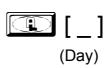
| 40. Set Weekday |
; [ _ ] :
; 4 0 (Day) |
|
|
For Example: To set day to Sunday;
Enter: ; 4 0 |
; 1 : | |
| 41. Daylight Saving Time Start Date | ;41;[ M M W D ] : | |
|
(DST Starting Month, Month, Week, Day)
The manner in which Daylight Saving Time (DST) is observed varies with location, therefore the DST adjustment is fully flexible to accommodate these regional differences. Function 41 allows the entry of a DST Start Date (month, day and week), and Function 42 allows the entry of a DST End Date (month, day and week). DST begins and ends at 2AM on the programmed date. Enter ; 41;000:to disable DST. All locks leave the factory with DST enabled and pre-programmed to the following start and end dates (for the USA beginning 2007): |
4 | |
|
|
Default DST Start Date: March, Week 2, Sunday ("Second Sunday in March")
Default DST End Date: November, Week 1, Sunday ("First Sunday in November") |
|
| To program the DST start date using the keypad, press: ;41;[ M M W D ] : where "M M W D" represents: | ||
|
preceding zero). |
"M M" = Two digits of the month (01 through 12 = January through December. Single digit months are entered with a | |
|
|
"W" = Single digit for "week of the month" (valid entries are 1-5 where "1" is the first week, "2" is the second week, "3" is
the third week, "4" is the fourth week and "5" is the last week of the month. "D" = Day of the week (valid entries are 1-7: 1 for Sunday, 2 for Monday, 3 for Tuesday, 4 for Wednesday, 5 for Thursday, 6 |
|
| for Friday and 7 for Saturday). |
Example: To set the default start date of "second Sunday in March", press:
;41;[ 0 3 2 1 ] : (03 = "March", 2 = "2nd week", 1 = Sunday). |
|
| 42. Daylight Saving Time End Date |
;42;[ M M W D ] :
(DST Ending Month, Month, Week, Day) |
CLOCK ADJUST
| Clock Adjust | |
|---|---|
|
Number of seconds to adjust (speed up/slow down) the clock each day must be be
tween 0-55 seconds. Note: Repeated use of these Functions are not "cumulative" (this means, for example, if the clock has already been set to speed up 10 seconds per day, and then is found to need an additional 10 seconds, then program 20 seconds using Function 43). Example 1: Clock is losing 13 seconds every day, enter: ; 1 3 :. ; 4 3 This example assumes that the Clock Adjust setting was at the factory default of zero. Function 57 can be used to print the current Clock Adjust setting. Example 2: Clock is gaining 13 seconds every day, enter: ; 1 3 :. ; 4 4 This example assumes that the Clock Adjust setting was at the factory default of zero. Function 57 can be used to print the current Clock Adjust setting. Example 3: To set the clock adjust setting back to the factory default of zero, enter: ; 4 3 : or ; 4 4 : |
4
Clock Accuracy The internal oscillator is factory calibrated to an accu racy of ±5 minutes/year. Changes in ambient tem perature may affect accuracy. If necessary, the accuracy of the internal clock may be adjusted by first updating the correct time via Function 39. After an inter val of about 1 month, re-set the correct time via Function 39 and then print an Audit Trail via Function 55. Be cause the Audit Trail displays both the "New Clock Time" and the "Old Clock Time", a daily accuracy (in seconds) can be determined by taking the difference in seconds between the "Old" and "New" times divided by the num ber of days between the two Function 39 entries. Note: Because the minimum available adjustment is 1 second per day, the inaccuracy of the clock must exceed about 6 minutes per year before adjustment is necessary. |
|
43. Speed Up Clock
(This Function enabled through keypad only) |
; [ ]:
; 4 3 (seconds) |
|
44. Slow Down Clock
(This Function enabled through keypad only) |
; [ ]:
; 4 4 (seconds) |
|
PASSAGE MODE
Passage Mode Enable/Disable - Schedule will Override Function 45 allows passage through the door without the need for a User Code. Re-Lock using Function 46. |
2 |
|
Programmed Schedules will override the state of the lock when Functions 45 and 46 are used. If it is required that pro
grammed schedules do not override Passage Mode, enable/disable Passage Mode using Functions 48/49. Note: Because of the temporary nature of these features, Functions 45-47 can only be enabled using the keypad. |
|
|
45. Enable Passage Mode
(This Function enabled through keypad only) |
; 4 5 : |
|
46. Disable Passage Mode
(This Function enabled through keypad only) |
; 4 6 : |
|
47. Timed Passage Mode
(This Function enabled through keypad only) |
; [ ] :
; 4 7 (XXX Hours) |
|
Hours must be between 1 - 999. Function 47 allows passage through the door without the need for a User Code for the programmed amount of time. For example, if you wish your office door lock to be unlocked (unlocked = "Passage Mode") for the next 3 hours, enter Program Mode and press: ;47;003: |
2 |
PERMANENT PASSAGE MODE
Passage Mode Enable/Disable - Schedule will not Override
- Function 48 allows passage through the door without the need for a User Code. Re-Lock using Function 49.
-
Programmed Schedules will not override the state of the lock using functions 48 and 49. If it is required that programmed schedules override Passage Mode, Enable/Disable Passage Mode using Functions 45/46. Use Function 50 to "undo" Functions 48 and/or 49, and therefore return the lock to all pre-existing scheduled functions.
Note:
Functions 48-50 can only be enabled using the keypad.
Warning:
Function 49 will inhibit all scheduled Passage Mode events.
- 48. Enable Permanent Passage Mode
(This Function enabled through keypad only)
49. Disable Permanent Passage Mode
(This Function enabled through keypad only)
50. Return Lock to Normal Passage Mode Schedule
(This Function enabled through keypad only) (Locks will lock or unlock depending on the current schedule). Use Function 50 to "undo" Functions 48 and/or 49, and therefore return the lock to all pre-existing scheduled functions.
NOTE: See Scheduled functions 72 and 73 for Scheduled Passage Mode.
PASS TIME
Pass Time
The Pass Time is the length of time the lock stays unlocked after a valid User Code is entered. When the Pass Time expires, the lock will re-lock automatically. Use the functions below to change the Pass Time to 3-5, 10 or 15 seconds. The Pass Time is defaulted to 3-5 seconds.
4
; 4 9:
; 5 0 :
; 4 8 :
2
51. Set Pass Time 3 to 5 Sec. ;51:
;52: 52. Set Pass Time to 10 Sec.
;53: 53. Set Pass Time to 15 Sec.
54. Reserved
PRINTER
Hold the printer's tab perpendicular to the Lock's infrared LED as shown in Figure 1 and Figure 2. If the printer has been idle for some time, press the paper feed button to "wake up" the printer.
5 5 *
(1) (5) (6) (*)
(1) (5) (7) (*)
(1) (5) (8) (*)
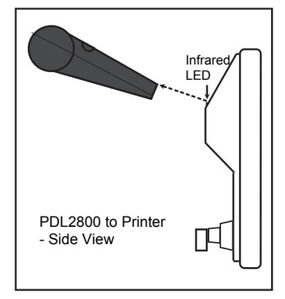
Figure 1
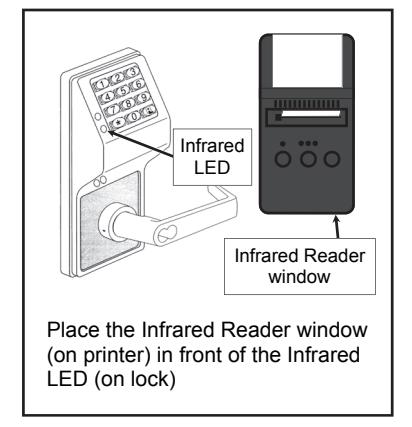
Figure 2
1
3
1
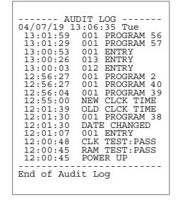
55. Print Audit Trail
Hold the printer over the lock's infrared sensor as shown in Figure 1 and Figure 2. 20 events will print at a time; press 1 for more events, or 9 to quit. To abort printing, press any key for 3 Sec (Three short beeps will sound).
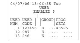
56. Print User Code List
Hold the printer over the lock's infrared sensor as shown in Figure 1 and Figure 2. To abort printing, press any key for 3 Sec (Three short beeps will sound).
57. Print Clock Settings and Software Version
Hold the printer over the lock's infrared sensor as shown in Figure 1 and Figure 2.
ALARM LOCK SYSTEMS, INC VERSION DL26 org REC 04/07/06 13:11:28 Tue Clock adjust setting +0 Cycle count hex 00000E F39 day ct hex 00
DOWNLOADING
58. Upload/Download PC Data
For use with DL-WINDOWS software, refer to OI237; an AL-PCI interface cable is needed.
3
AL-DTM
59. Reserved
LOCKOUT
60. Number of Attempts Before Lockout

- Number of attempts before lockout must be 1-9 attempts.
- The number of attempts is reduced by half every time the keypad is locked out without a successful code entry (default is 6 attempts).
- The attempt count is reset each time a valid code is entered.
61. Set the Attempts Lockout Time

Lockout Time must be 1-60 seconds. This functions defines how long the keypad is locked out after a series of unsuccessful attempts (default is 15 seconds).
4
2
4
62-63. Reserved
REMOTE INPUT
Remote Input Disable/Enable
- Wire a Normally Open Contact to Terminals 3 & 4. Momentarily close to allow person to pass through door.
- Enter the functions below to Disable/Enable the Remote Input.
NOTE: The Remote Input is enabled as part of the default program.
- 64. Disable Remote Input ; 6 4 :
- 65. Enable Remote Input ; 6 5 :
66. Reserved
67. Reserved
ENTER KEY
Enter Key Enable/Disable (Allows Programming of Codes that Match the 1st digits of other Codes)
-
When enabled, the user must press : after a User Code entry, allowing User Codes to be subsets of other User Codes. For example: 1 2 3 : is a valid User Code; 1 2 3 4 :is also a valid User Code
4
- 69. Enable : as Enter Key ; 6 9 :
- 70. Disable : as Enter Key ; 7 0 :
71. Reserved
SCHEDULES
Scheduled Passage Mode Enable/Disable
Mode (Unlock)
Use the functions below to Enable/Disable Schedule Passage Mode. For day enter: 1 for Sunday, 2 for Monday, 3 for Tuesday, 4 for Wednesday, 5 for Thursday, 6 for Friday, 7 for Saturday, 8 for Monday to Friday, 9 for Saturday and Sunday, 0 for all days of week.
; 7 2 ;[ _ ] ; [ _ _ _ _ ] :
73. Schedule Disable Passage Mode (Lock)
72. Schedule Enable Passage
; 7 3 ;[ _ ] ; [ _ _ _ _ ] :(Day) (Time)
(Day) (Time)
SCHEDULES
NOTE: Clear All Schedule and Timeout Functions by entering Function 12.
3
Scheduled Group Enable/Disable
Use the functions below to Enable/Disable Groups at the time programmed.
For day enter: 1 for Sunday, 2 for Monday, 3 for Tuesday, 4 for Wednesday, 5 for Thursday, 6 for Friday, 7 for Saturday, 8 for Monday to Friday, 9 for Saturday and Sunday, 0 for all days of week.
74. Schedule Enable Group 1 ; 7 4 ; [ _ ] ; [ _ _ _ _ ] :
3
(Day) (Time)
75. Schedule Enable Group 2 ; 7 5 ; [ _ ] ; [ _ _ _ _ ] :
(Day) (Time)
76. Schedule Enable Group 3 ; 7 6 ; [ _ ] ; [ _ _ _ _ ] :
(Day) (Time)
77. Schedule Enable Group 4 ; 7 7 ; [ _ ] ; [ _ _ _ _ ] :
(Day) (Time)
78. Schedule Enable All Groups ; 7 8 ; [ _ ] ; [ _ _ _ _ ] :
(Day) (Time)
79. Schedule Disable Group 1 ; 7 9 ; [ _ ] ; [ _ _ _ _ ] :
(Day) (Time)
80. Schedule Disable Group 2 ; 8 0 ; [ _ ] ; [ _ _ _ _ ] :
(Day) (Time)
81. Schedule Disable Group 3 ; 8 1 ; [ _ ] ; [ _ _ _ _ ] :
(Day) (Time)
82. Schedule Disable Group 4 ; 8 2 ; [ _ ] ; [ _ _ _ _ ] :
(Day) (Time)
83. Schedule Disable All Groups ; 8 3 ; [ _ ] ; [ _ _ _ _ ] :
(Day) (Time)
QUICK SCHEDULES
Quick Schedules - Enable Group
For your convenience, your lock comes pre-programmed with Quick Schedules, which, when programmed, enable Groups for popular blocks of time. Group members will be enabled during the blocks of time defined below, but will still need to enter their User Codes into the keypad to unlock the lock.
Group number must be 1-4; enter the number of the Group that is to be enabled for the time specified by the Quick Schedules below.
Note: These Quick Schedules can only be programmed through the keypad (not through DL-Windows), and existing Quick Schedules will be over-written by schedules downloaded from DL-Windows. Therefore, after downloading any DL-Windows schedules, be sure to re-program your Quick Schedules into your Lock Program.
|
84. Business Quick Schedule
7AM-5PM, Monday - Friday |
; 8 4 |
; [ _ ]:
(Group) |
|---|---|---|
|
85. Day Quick Schedule
7AM-5PM, All days |
; 8 5 |
; [ _ ]:
(Group) |
|
86. Evening Quick Schedule
3PM-1AM, All days |
; 8 6 |
; [ _ ]:
(Group) |
|
87. Night Quick Schedule
11PM-9AM, All days |
; 8 7 |
; [ _ ]:
(Group) |
SCHEDULES GROUP 1 ACTIVATED
Scheduled Passage Mode (Group 1 Activated)
Functions 88 and 89 allow you to set up a window of time where if any Group 1 User Code is entered within this window, Passage Mode will be activated, allowing anyone to enter. Note: This feature can only be programmed using the lock keypad. For additional information, see Group 1 Activated Features on page 27.
3
- For the day enter: 1 for Sunday, 2 for Monday, 3 for Tuesday, 4 for Wednesday, 5 for Thursday, 6 for Friday, 7 for Saturday, 8 for Monday to Friday, 9 for Saturday and Sunday, and 0 for all days of week.
- Enter time of day in 24 hour format (for example, for 2:15 PM, enter 14:15).
Be sure to lock manually or schedule a single-ended Lock event to coincide with the End Time. For example, program the device to automatically lock (disable Passage Mode) every night at 5 PM by using Function 73, as follows: ; 73 ;0;1700:
| 88. Passage Mode | ; 8 8 | ;[ _ ] | ;[ ] : |
|---|---|---|---|
| (Open Time Window) | (Day) | (Time) | |
| 89. Passage Mode | ; 8 9 | ;[ _ ] | ;[ ] : |
| (Close Time Window) | (Day) | (Time) |
3
90. Reserved
91. Reserved
Scheduled Group 4 Enable (Group 1 Activated)
Functions 92 and 93 allow you to set up a window of time where if any Group 1 User Code is entered within this window, Group 4 members will be enabled. (Group 4 members will still need to enter their User Codes to enter). For additional information, see Group 1 Activated Features on page 27.
3
- For day enter: 1 for Sunday, 2 for Monday, 3 for Tuesday, 4 for Wednesday, 5 for Thursday, 6 for Friday, 7 for Saturday, 8 for Monday to Friday, 9 for Saturday and Sunday, and 0 for all days of week.
- Enter time of day in 24 hour format (for example, for 2:15 PM, enter 14:15).
92. Enable Group 4 (Open Time Window)
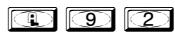


93. Enable Group 4 (Close Time Window)
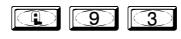

94 - 98. Reserved
CLEAR ALL PROGRAMMING
99. Clear All Lock Programming ; 9 9 ; 0 0 0:


Clears all programming and returns lock to factory default settings. Audit Trail contents are maintained.
M
Groups and Scheduled Group 1 Examples
The following examples detail the more advanced features of the DL2800 lock. Although all features and device functions can be programmed using the lock keypad, when programming becomes more complex you may find it easier to use DL-Windows software to program your Alarm Lock security lock. For more information, contact your Alarm Lock security professional.
Assign a User to Two Groups
Create a User 101 (all Users 101-150 are members of Group 2 by default) and include User 101 in Group 3 (as well as the default Group 2).
- 1. Enter Program Mode (if not in already).
- 2. Using Function 2, create User 101 with a User Code of "789":
Press ;2;101;789: .
3. Using Function 35, make User 101 a member of Group 2 and 3: Press ;35;101;23: .
4. Exit Program Mode.
Note: See step 3 above--although User 101 is by default a member of Group 2, you must include Group 2 when using Function 35 or the Group 2 association will be removed.
The example to add Users to Group 2 and Group 3 has been selected due to the fact that Group 1 Activated Functions require that a member of Group 1 enter their User Code to activate the Function, and it may become necessary to assign Users to Groups.
Group 1 Activated Features: Functions 88/89 and 92/93
- Function 88 and 89 allow for a window of time to be created where if any Group 1 User Code is entered within the programmed window, Passage Mode will be activated (the device physically unlocks, allowing passage for all). If a Group 1 User does not enter their User Code during the specified window, Functions 88/89 remain inactive.
- Function 92 and 93 allow for a window of time to be created where if any Group 1 User Code is entered within the programmed window, the User Codes in Group 4 will be enabled. If a Group 1 User does not enter their User Code during the specified window, Functions 92/93 remain inactive. Companies typically use this feature to allow Group 1 Managers the ability to enable all Group 4 staff members during a certain window of time.
The following examples illustrate how Functions 88-93 can be programmed into your DL Series lock via the keypad:
Functions 88/89 : Use Function 88 to set an Open Time Window (during which the Group 1 User must enter their User Code), and then use Function 89 to set the time to close the Window. Re-lock the door at night manually (Function 46).
- 1. Enter Program Mode (if not in already).
- 2. Using Function 2, create User 4 with a User Code of "456789":
Press ;2;4;456789: .
3. Because User 4 does not have a default Group association, make User 4 a member of Group 1 using Function 35:
Press ;35;4;1: .
4. Use Function 88 and Function 89 (see page 25) to designate Passage Mode as being between the hours of 8:30 A.M. and 10 A.M. for all days of the week:
Function 88 (Open Window Time) = 8:30 A.M.: Press ;88;0;0830:
Function 89 (Close Window Time) = 10:00 A.M.: Press ;89;0;1000:
5. Exit Program Mode (hold down any key for 3 seconds).
The lock will now be put in Passage Mode (device physically unlocked) if User 4 (or any Group 1 member) enters their User Code between 8:30 A.M. and 10 A.M. If a Group 1 User does not enter their User Code during the specified window, Functions 88/89 remain inactive
The device will have to be manually locked each night by entering the following command using Function 46:
;46:
The device can also be programmed to automatically lock (disable Passage Mode) each night at 5 P.M. by using Function 73:
; 73 ;0;1700:
Remember to exit Function Mode when programming is complete.
Groups and Scheduled Group 1 Examples (cont'd.)
Functions 92/93 : Use Function 92 and 93 (see page 26) to create a window of time where if any Group 1 User Code is entered within the programmed window, Group 4 Users will be enabled.
| 1. Enter Program Mode (if not in already). |
|---|
2. Using Function 2, create User 4 with a User Code of "456789": Press ;2;4;456789: .
3. Because User 4 does not have a default Group association, make User 4 a member of Group 1 using Function 35:
Press ;35;4;1: .
4. Using Function 17, disable Group 4. (Group 4 will need to be "disabled" before it can be "enabled" later). Press ;17: .
5. Use Function 92 to set the time to open the window (8:30 A.M. all days of the week) allowing any Group 1 member to enable Group 4. Use Function 93 to set the time to close the window (10:00 A.M. all days of the week).
Function 92 (Open Window Time) = 8:30 A.M.: Press ;92;0;0830:
Function 93 (Close Window Time) = 10:00 A.M.: Press ;93;0;1000:
6. Exit Program Mode (hold down any key for 3 seconds).
The lock will now enable Group 4 User Codes if User 4 (or any Group 1 member) enters their User Code between 8:30 A.M. and 10 A.M. If no Group 1 member arrives to enter their User Code between 8:30 A.M. and 10 A.M., Group 4 User Codes will not be enabled and will remain disabled all day.
The device will have to be manually locked each night by entering the following command using Function 82:
; 46 :
The device can also be programmed to automatically disable Group 4 members each night at 5 P.M. by using Function 82:
; 82 ;0;1700:
Test the device by creating User 222 (with User Code 466466) and adding User 222 to Group 4:
;2;222;466466:
;35;222;4:
Remember to exit Function Mode when programming is complete.
Programming Record Sheet
Default Values are shown in parentheses.
|
Function
Number(s) |
Function Name | Programming |
|---|---|---|
| 40/41 |
Daylight Savings Time Enable/
Disable |
Enable [ ]
Disable [ ] (Enable) |
| 43/44 | Clock Adjust |
+/-
0-55 seconds Seconds (0) (0) |
| 51/52/53 | Pass Time |
3-5 sec [ ]
10 sec [ ] 15 sec [ ] (3-5 sec) |
| 60 | Number of Attempt Before Lockout |
1-9 attempts
Attempts (6) |
| 61 | Set the Attempts Lockout Time |
1-60 seconds
(1) (5) Seconds |
| 64/65 | Remote Input Disable/Enable |
Enable [ ]
Disable [ ] (Enable) |
| 69/70 | Enter Key Enable/Disable |
Enable [ ]
Disable [ ] (Disable) |
User Code Record Sheet
Page___
|
User Number
(1-200) |
User Code
(3-6 digits) |
Group
Association |
Programming
Level |
Full Name | ||||||||||
|---|---|---|---|---|---|---|---|---|---|---|---|---|---|---|
| 1 | 2 | 3 | 4 | 1 | 2 | 3 | 4 | |||||||
|
|
||||||||||||||
| _ | ||||||||||||||
| | | ||||||||||||||
| | | ||||||||||||||
Note:
To obtain a complete list of User Codes, use either the remote printer (see Program Function 56) or use DL-WINDOWS download software.
Schedule Record Sheet
| Day(s) | ||||
|---|---|---|---|---|
| Up to 150 scheduled functions can be programmed. For | ||||
| Function Number |
Day Enter :
1 = Sunday, 2 = Monday, 3=Tuesday, 4 Wednesday 5 = Thursday, 6 = Friday, 7=Saturday, 8 = Monday - Fri |
Time | Function Name | |
|
day
9 = Saturday and Sunday, 0=All days of the week |
||||
| Enter time of day in 24 hour format (00:00- 23:59) | : | |||
| : | ||||
| : | ||||
| : | ||||
| : | ||||
| : | ||||
| : | ||||
| : | ||||
| : | ||||
| : | ||||
| : | ||||
| : | ||||
| : | ||||
| : | ||||
| : | ||||
| : | ||||
| : | ||||
| : | ||||
| : | ||||
| : | ||||
| : | ||||
| : | ||||
| : | ||||
| : | ||||
| : | ||||
| : | ||||
| : | ||||
| : | ||||
| : | ||||
| : | ||||
| : | ||||
| : | ||||
| : | ||||
Glossary
ACCESS = Entry into a restricted area.
AUDIT TRAIL = A date/time stamped log of previous lock events.
BURGLARY CONTROL PANEL = Provides local alarm and remote communication to request security for burglary/break-in.
CLOCK
- REAL TIME CLOCK = An accurate built-in clock that allows date/time stamping of events. The clock can be slowed or speeded up to fine tune long term accuracy to within three minutes per year.
- CLOCK SETTINGS = Printout includes date, time, weekday, and clock speed.
- CLOCK SPEED = The clock can be adjusted to allow faster/slower speeds and therefore increasing clock accuracy.
CODE = Numeric sequence of numbers (such as: 1234) entered at the keypad. If Star-Enter-Key is required, must be followed by a [ : ] key.
- BASIC USER CODE = User Codes assigned to User Numbers 12+ (except Users 299-300). (Basic User Codes do not allow programming)
- INVALID CODE = A User Code that has not been programmed in the lock.
- MANAGER CODE = User Codes assigned to User Numbers 2 through 6. (Allows most programming functions).
- MASTER CODE = The User Code assigned to User Number 1. The Default (factory) Master Code is 123456. The User with the Master Code has complete control of the lock (no programming restrictions).
- SERVICE CODE = User 300 User Code. Allows only one use, then must be re-enabled by Function 9.
- SUPERVISOR CODE = User Codes assigned to Users 7 through 11. Can only program certain day-today operational functions.
- USER CODE = Code used by Users. A User Code is 3 to 6 numeric digits long, pressed into the keypad buttons, allowing controlled entry by Users.
VALID CODE = An entered User Code that has been programmed in the Lock Program.
COM PORT = A computer serial communications port used to communicate with the Lock and/or Data Transfer Module.
DATA TRANSFER MODULE = A device that permits transfer of program/data between a computer and the lock.
DATE = Month, Day and Year entered as MMDDYY.
DAY OF WEEK = Sunday through Saturday (where 1 = Sunday and 7 = Saturday).
DEFAULT = Default settings are the original settings that were set at the factory; in other words, it is the lock's original factory condition when the lock was first taken out of its original box. The default settings are permanently encoded within the lock's fixed memory, and when the lock is first started, or when power is removed and re-applied (see Wiring, Power-Up & Battery Replacement, page 10), the original factory default settings are re-loaded and take effect.
DISABLE = Turn off.
DOOR NUMBER = Identification of each door lock with a specific number in order to ensure that the correct lock is associated with the correct lock programming within DL-Windows or the AL-DTM. Note: "Door Number" is a term used with AL-DTM versions 1 and 2 and with DL-Windows versions 3.5.0 and earlier. Later versions of the AL-DTM and DL-Windows monitor door numbers automatically, therefore there is no need to manually change door numbers via the keypad. Therefore, Function 59 is no longer used with the later versions of the AL-DTM and DL-Windows.
DOWNLOAD = To receive data from the lock into the AL-DTM or DL-Windows.
ENABLE = Turn on.
EVENTS = Recorded lock activity.
FUNCTION (also called Programming Functions ) = are the numbers used to program lock features (enabling/disabling Users, User Groups, Passage Mode, Schedules, etc.).
Glossary (cont'd)
GROUP
- USER GROUP = Defining a User to specific Groups, allows User entry when the Group is allowed entry.
- GROUP 1 ENABLES GROUP 4 USERS = A Group 1 USER CODE entry during a predefined schedule will allow access to Group 4 Users. See page 26.
- GROUP 1 PUTS UNIT IN PASSAGE = A Group 1 USER CODE entry during a pre-defined schedule will unlock unit. See page 25.
GUARD TOUR = A Guard Tour Code is used to log the movement of a security guard as he or she makes rounds from one assigned guard tour station to the next. See " User 300: One-Time Only Service Code " on page 8 for more information.
INSTALLER = See.... CODE, INSTALLER CODE.
KEYPAD = 10-numeric keys, : and special ; key.
- KEYPAD LOCKOUT = Keypad is programmed to lockout Users, for a specified period of time, when a specified number of invalid User Codes are entered.
- KEYPAD PROGRAMMING = Ability to program the lock through the keypad.
KEYPRESS = Pressing a button on the lock's keypad.
LEVEL ABILITY = Predefined User Types (such as Master, Manager and Supervisor) each having specific abilities to program and/or control the lock.
LOCK PROGRAM = A Lock Program is stored within the lock's circuitry and contains the instructions that the lock uses to perform its various functions. You can use the keypad to change the Lock Program, and you can also use DL-Windows to create a Lock Program on your computer, and then transfer and store the Lock Program within the lock.
LOCKOUT ATTEMPTS = A specified number of invalid User Code entries (1-9), that will disable the keypad for a predefined period of time (1-60 seconds).
LOCKOUT TIME = A predefined time (1-60) seconds
that the lock will stop accepting User Codes, after a specified number of invalid User Code entries (1-9).
LOG = See... AUDIT TRAIL.
MANAGER = See... CODE, MANAGER CODE.
MASTER = See... CODE, MASTER CODE.
PASSAGE = Allow anyone to pass through the door without USER CODES (lock remains unlocked thus allowing passage).
PRINTER = A printout device such as an infrared printer or computer printer.
PROGRAM MODE = A mode allowing program/data to be entered through the keypad. Only specific Users (Master, Managers and Supervisors) can program a lock manually, by entering their USER CODE, followed by the [ ; ] key.
REMOTE INPUT = Entry into a restricted area, by pressing a button connected to the REMOTE INPUT WIRES (White and White) by someone on the other side of the door.
SCHEDULE = A programmed operation (enable/ disable, lock/unlock, etc.) on a specific day (Sunday through Saturday) and time.
SCHEDULES, QUICK = Any one of four most common types of schedules can be programmed.
TIME = Hours and Minutes in the HHMM format.
TIME/DATE STAMP = A recorded date and time that an event occurred.
TIMEOUT = Immediate operation for a specified number of hours.
UPLOAD = To send data from the AL-DTM or DL-Windows to the lock .
USER = A person who has been provided with a US-ER CODE for access through the door.
USER LOCKOUT, TOTAL = All User Codes have been disabled, thus "locking out" all Users (except for Master Code).
| NOTES |
|---|
ALARM LOCK LIMITED WARRANTY
ALARM LOCK SYSTEMS, INC. (ALARM LOCK) warrants its products to be free from manufacturing defects in materials and workmanship for twenty four months following the date of manufacture. ALARM LOCK will, within said period, at its option, repair or replace any product failing to operate correctly without charge to the original purchaser or user.
This warranty shall not apply to any equipment, or any part thereof, which has been repaired by others, improperly installed, improperly used, abused, altered, damaged, subjected to acts of God, or on which any serial numbers have been altered, defaced or removed. Seller will not be responsible for any dismantling or reinstallation charges, environmental wear and tear, normal maintenance expenses, or shipping and freight expenses required to return products to ALARM LOCK. Additionally, this warranty shall not cover scratches, abrasions or deterioration due to the use of paints, solvents or other chemicals.
THERE ARE NO WARRANTIES, EXPRESS OR IM-PLIED, WHICH EXTEND BEYOND THE DESCRIPTION ON THE FACE HEREOF. THERE IS NO EXPRESS OR IMPLIED WARRANTY OF MERCHANTABILITY OR A WARRANTY OF FITNESS FOR A PARTICULAR PUR-POSE. ADDITIONALLY, THIS WARRANTY IS IN LIEU OF ALL OTHER OBLIGATIONS OR LIABILITIES ON THE PART OF ALARM LOCK.
Any action for breach of warranty, including but not limited to any implied warranty of merchantability, must be brought within the six months following the end of the warranty period.
IN NO CASE SHALL ALARM LOCK BE LIABLE TO ANY-ONE FOR ANY CONSEQUENTIAL OR INCIDENTAL DAMAGES FOR BREACH OF THIS OR ANY OTHER WARRANTY, EXPRESS OR IMPLIED, EVEN IF THE LOSS OR DAMAGE IS CAUSED BY THE SELLER'S OWN NEGLIGENCE OR FAULT.
In case of defect, contact the security professional who installed and maintains your security system. In order to exercise the warranty, the product must be returned by the security professional, shipping costs prepaid and insured to ALARM LOCK. After repair or replacement, ALARM LOCK assumes the cost of returning products under warranty. ALARM LOCK shall have no obligation under this warranty, or otherwise, if the product has been repaired by others, improperly installed, improperly used, abused, altered, damaged, subjected to accident, nuisance, flood, fire or acts of God, or on which any serial numbers have been altered, defaced or removed. ALARM LOCK will not be responsible for any dismantling, reassembly or reinstallation charges, environmental wear and tear, normal maintenance expenses, or shipping and freight expenses required to return products to ALARM LOCK. Additionally, this warranty shall not cover scratches, abrasions or deterioration due to the use of paints, solvents or other chemicals.
This warranty contains the entire warranty. It is the sole warranty and any prior agreements or representations, whether oral or written, are either merged herein or are expressly cancelled. ALARM LOCK neither assumes, nor authorizes any other person purporting to act on its behalf to modify, to change, or to assume for it, any other warranty or liability concerning its products.
In no event shall ALARM LOCK be liable for an amount in excess of ALARM LOCK's original selling price of the product, for any loss or damage, whether direct, indirect, incidental, consequential, or otherwise arising out of any failure of the product. Seller's warranty, as hereinabove set forth, shall not be enlarged, diminished or affected by and no obligation or liability shall arise or grow out of Seller's rendering of technical advice or service in connection with Buyer's order of the goods furnished hereunder.
ALARM LOCK RECOMMENDS THAT THE ENTIRE SYS-TEM BE COMPLETELY TESTED WEEKLY.
Warning: Despite frequent testing, and due to, but not limited to, any or all of the following; criminal tampering, electrical or communications disruption, it is possible for the system to fail to perform as expected. ALARM LOCK does not represent that the product/system may not be compromised or circumvented; or that the product or system will prevent any personal injury or property loss by burglary, robbery, fire or otherwise; nor that the product or system will in all cases provide adequate warning or protection. A properly installed and maintained alarm may only reduce risk of burglary, robbery, fire or otherwise but it is not insurance or a guarantee that these events will not occur. CONSEQUENTLY, SELLER SHALL HAVE NO LIA-BILITY FOR ANY PERSONAL INJURY, PROPERTY DAMAGE, OR OTHER LOSS BASED ON A CLAIM THE PRODUCT FAILED TO GIVE WARNING. Therefore, the installer should in turn advise the consumer to take any and all precautions for his or her safety including, but not limited to, fleeing the premises and calling police or fire department, in order to mitigate the possibilities of harm and/or damage.
ALARM LOCK is not an insurer of either the property or safety of the user's family or employees, and limits its liability for any loss or damage including incidental or consequential damages to ALARM LOCK's original selling price of the product regardless of the cause of such loss or damage.
Some states do not allow limitations on how long an implied warranty lasts or do not allow the exclusion or limitation of incidental or consequential damages, or differentiate in their treatment of limitations of liability for ordinary or gross negligence, so the above limitations or exclusions may not apply to you. This Warranty gives you specific legal rights and you may also have other rights which vary from state to state.