Alarm Lock RR-PM1200 Electromagnetic Lock Installation Programming instructions
Open the original PDF document
View PDF
345 Bayview Avenue Amityville, New York 11701 For Sales and Repairs, (800) 645-9445 For Technical Service, (800) 645-9440 © ALARM LOCK 2000 WI1020 08/00
RR-PM1200PAK INSTALLATION & PROGRAMMING INSTRUCTIONS
GENERAL DESCRIPTION
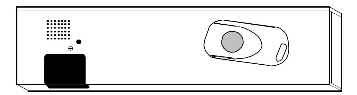
The Alarm Lock Remote Release PowerMag is an innovative 1200 lb. electromagnetic locking system with infrared remote control(s). The Alarm Lock System (model RRPM1200PAK) offers the security of a mag and the convenience of pocket-size infrared keyfobs for management, staff or receptionists--up to 100 individual remote controls (part no. AL-REMOTE) are supported! These lithium-battery powered remote controls can release the mag from either side of the door and feature easy single button operation.
SYSTEM FEATURES
- Advanced 1200 Lb. Electromagnetic Lock with Innovative Infrared Remote Release
- The power of a Magnetic Lock with the convenience of pocket-size remote controls for reception or staff..
- Unique patented feature allow the Power Mag to sense the door status and provide high end options such as door chime, door held open alarm, relay output follows door position, etc..
- Complete RR-PM1200PAK turnkey system includes: Advanced 1200 Lb. Power Mag, one AL-REMOTE KeyFob remote control, and plug-in AC transformer.
- Plug-in 12 V AC transformer eliminates the requirement for running wires or employing an electrician's services.
- Supports up to 100 individual KeyFobs (model no. AL-REMOTE).
- KeyFobs release Power Mag from either side of door.
- KeyFobs feature single button operation with positive "click" response.
- KeyFobs are automatically-enrolled by system in easy programming mode and each is audibly and visually confirmed.
- Can optionally be powered by Alarm Lock Regulated Power Supplies (AL-P1A, AL-P3A, or AL-P6A).
- Programmable remote switch functions.
- All programming stored in non-volatile memory will not be lost on loss of power.
- UL Listed; CE
SPECIFICATIONS
Input Power 12 Volt AC Plug In, Class 2 Transformer,
(AC) 8.5 to 20 VA.
Input Power optional 12V, 500 mA DC power supply
(DC) required per Maglock.
1200PM 2.875" x 10.5" x 1.5" / 7.3cm x 26.8cm x 3.8cm
Dimensions: (HxWxD)
AL-REMOTE Protected Side (inside): 35 feet (min.)
Range: Unprotected Side (outside): 10 feet (min)
ORDERING INFORMATION
AL-REMOTE additonal IR KeyFob for PM1200 system.
PM1200 1200lb MagLock (w/o transformer or
AL-REMOTE)
Mounting the PM1200 POWER MAG
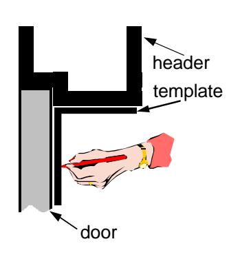
- 1 Fold template where indicated to form a 90° angle. For a swinging door place template against door header and door opposite hinge side of door jamb. For a pair of swinging doors place template against door and door header at center of door opening. Transfer ARMATURE PLATE MOUNTING hole locations to door. If outside access is required, the "LIGHT PIPE HOLE" location should also be transferred at this time. DO NOT transfer door frame hole locations to header at this time.
- 2 Follow template instructions for hole sizes. Use the illustrations below to determine proper armature mounting hole
rubber washer
5/16" 18 screw Solid Door armature sexnut 1 3/8" washers
Drill 11/32" hole through door. From sexnut side of door drill 1/2 dia. hole 1 3/8" deep. Mount armature to door with hardware provided.
door
1/2"
Hollow Steel Door
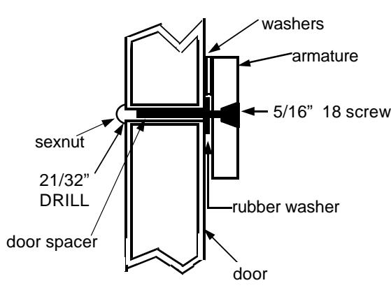
Drill 11/32" hole through door. From sexnut side of door drill 21/32 hole through only one side of door. Mount armature to door with hardware provided.
3 Note type of door frame header and install filler plate or angle bracket as required to provide a flat surface on the header over the entire depth of the lock.
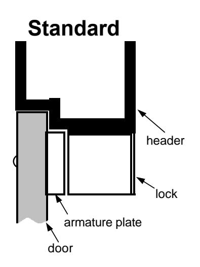
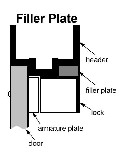
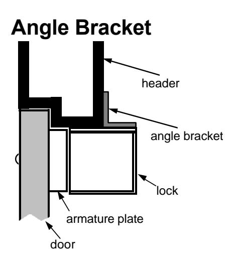
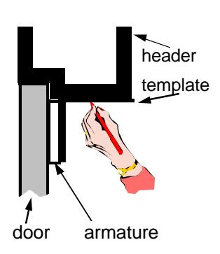
4 Fold template where indicated to form a 90° angle. Place template against the ARMATURE and the Door Header. Transfer MOUNTING PLATE hole locations to the header.
View of Mounting Plate Under the Header
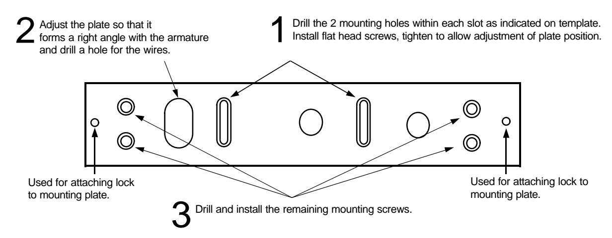
- 5 Install mounting plate to header by drilling pilot holes at slot locations (see item 1 in above drawing), then secure plate with 2 flat head screws. These two (2) screws are installed in the slotted holes to allow for adjustment before drilling and installing the (4) remaining outer screws (item 3 in above drawing).
- 6 Adjust the mounting plate so that it and the armature plate form a right angle.
- 7 Using the mounting plate as a template, drill the wire hole and pilot holes for the four (4) outer flat head screw positions.
- 8 Install the four (4) #10 flathead screws provided.
- 9 Fasten the lock to mounting plate with the two (2) 1/4-20 socket screws provided. Compensate for any misalignment by adding or subtracting washers at armature mounting screw.
- 10 Firmly tighten all screws. Install anti-tamper plugs into holes over each socket head mounting screw. Use soft hammer to avoid damaging lock case.
- 11 Rubber on armature screw head must not be trimmed or modified for correct operation.
NOTE: For steel door frame use self tapping flat head screws supplied; for wood door frames use the supplied wood screws.
Installing the Infrared Light Pipe.
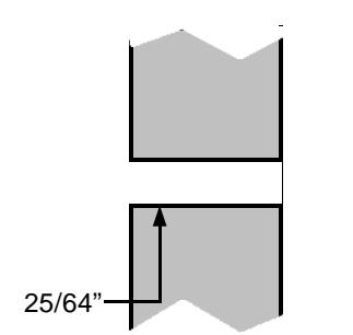
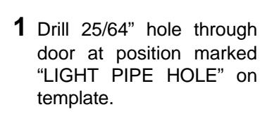
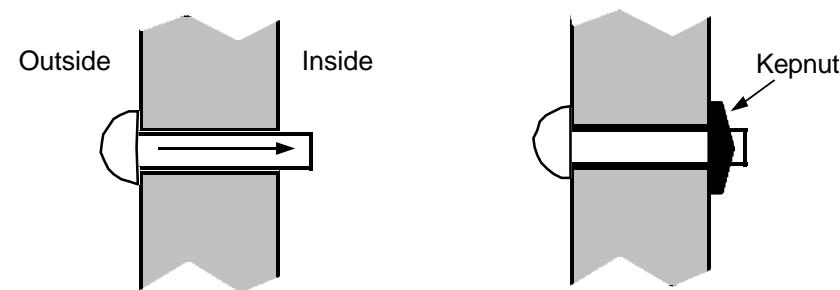
2 From outside of door slide light pipe through hole.
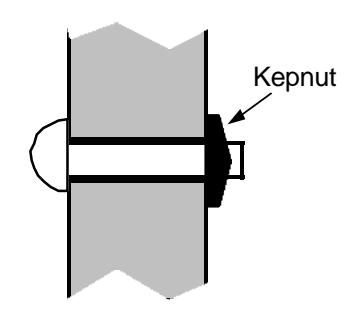
3 Firmly press supplied kepnut over the shaft of the light pipe until it is held securely against door.
Wiring the PM1200 POWER MAG
- 1 Open wiring bay cover by removing Phillips head screw.
- 2 Bring outside wires into wiring bay through wire access hole at top of bay.
- 3 Cut wire down to appropriate length and make connections using supplied wire nuts.
- 4 Carefully tuck wires back into the wiring bay.
- 5 Close cover.
Note: Only the Black AC power wires are mandatory connections. All others are optional.
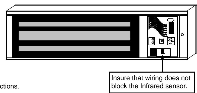
Power Connections
BLACK BLACK
Connect to the supplied 12V AC 10 VA Plug in transformer, or to an optional 12V DC 500 mA Power supply.(DC input is non polarized)
Remote Switch Input
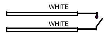
Connect to a normally open door bell push-button, momentary remote release push-button or latched passage mode switch. (See Remote Switch Input options in System Option Programming Commands)
Auxiliary Relay Output
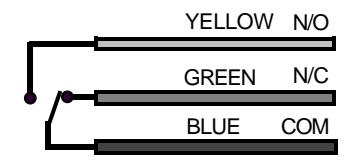
Wire the Auxiliary Relay Output to an optional peripheral device. (See Auxiliary Relay Output options in System Option Programming Commands)
Relay Contact rated for 12 V DC, 1 Amp Max.
The AL-REMOTE KeyFob
The AL-REMOTE KeyFob is a dual infrared element device which transmits a digitally encoded infrared signal to the Power Mag. The operational range of the KeyFob is a minimum of 35 feet from the Power Mag. When used from the protected side of the door (inside), aiming the KeyFob in the general direction of the Power Mag is sufficient. However, if using the supplied light pipe to allow access from the outside, the KeyFob must be aimed at the light pipe in order to activate the Power Mag.
An indication that the batteries inside the KeyFob are low and must be replaced will be a noticeable decrease in the effective range of the KeyFob. For example, if the KeyFob range is typically 35 feet and it falls to 20 feet, this is an indication that the batteries should be replaced.
The KeyFob should not be exposed to extreme temperatures and should not be submersed in water.
Replacing the AL-REMOTE KeyFob batteries
Following is the procedure for replacing the KeyFob batteries. The replacement battery is a Duracell model DL2032. (2 required). Warning: Replace batteries only with the same type as specified above. Use of another battery may present a risk of fire or explosion. Do not recharge or disassemble battery, or dispose of in fire.
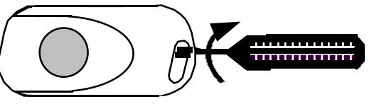
1 Insert flat blade screwdriver into the slot between the key ring loops and gently twist until the case pops open.
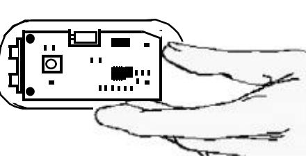
2 Gently lift circuit board from KeyFob base to expose the battery compartment.
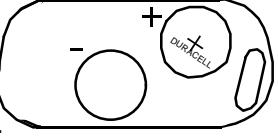
3 Remove old batteries. Observing polarity (+ / -), insert new batteries.
4 Place circuit board back into base over new batteries.
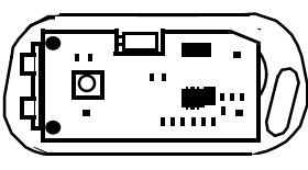
5 Align top of housing to base and snap together.
Programming the RR-PM1200
There are 2 modes of programming KeyFobs into the PM1200 data base. First, on initial power up the system automatically enters the Initial KeyFob Programming mode and will sequentially enroll any activated KeyFobs into the KeyFob database. The first KeyFob will be stored as 00 and the second as 01, up to the maximum of 99. The second method, Advanced Programming, is used for enrolling and deleting KeyFobs from an existing lock data base. A 16 position rotary switch and a push button located on the circuit board in the wiring bay of the Power Mag are used for advanced programming.
Initial KeyFob Programming
| Action | LED Response | Sounder Response | Comments | ||
|---|---|---|---|---|---|
| 1 | Power Up new Lock | Slow Flash | BEEP | Auto program mode entered. | |
| 2 | Wait a few seconds | Rapid Flash | Ready to enroll first KeyFob. | ||
| 3 | Aim KeyFob at Mag lock and press and hold button. | Solid light | 3 BEEPS | KeyFob enrolled as KeyFob 00 | |
| 4 | Release button. | Rapid Flash | Ready to enroll next KeyFob | ||
| Repeat steps 3 and 4 to enroll additional KeyFobs which will be sequentially stored in database (01, 02, 03, 04) | |||||
| When done, press and hold PGM button for 5 seconds. | Solid light if door is closed & locked | BEEPLONG BEEP | Exit Program Mode. | ||
You MUST program at least one KeyFob into the Power Mag database in order for the lock to function properly. The PM1200 will NOT function as a stand-alone Power Mag if not programmed.
Advanced Programming
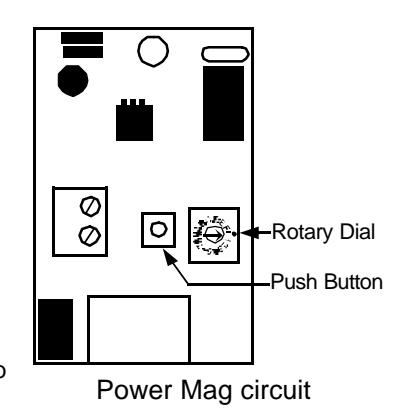
Once the Initial KeyFob enrollment has been completed, the Advanced Program Mode is used for subsequent programming of KeyFobs into the system. Advanced Programming is accomplished through a 16 position Rotary Dial Switch and a push button mounted in the Power Mag wiring compartment. The Rotary Dial and Push Button are used to set the User Number to which the keyfob is to be assigned.
- Unlock Power Mag with valid KeyFob
- Open Door
- Remove Cover from Power Mag Wiring Bay
- Locate the Rotary Dial and Push Button on the Power Mag circuit board.
- Press and Hold Power Mag push button until 1st beep.
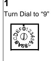
- 1 Turn Switch to the number representing the 1st digit of the User Number to be learned.
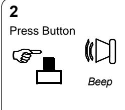
- Press the circuit board Push Button (the sounder will beep)
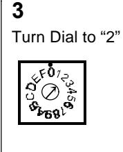
- 3 Turn Switch to the number representing the 2nd digit of the User Number to be learned.
- 4 Press the circuit board Push Button (the sounder will be-bop)
-
5 Aim the KeyFob to be programmed at the Power Mag and press the KeyFob button.
- The sounder will beep 3 times when accepted and the LED will light and stay lit.
-
6 Release the KeyFob button
- The LED will flash rapidly if next consecutive location in database is available for next KeyFob to be enrolled, or slowly if next address is already taken.
- 7 When programming is complete, hold PGM Push button for 5 seconds to exit program mode.
Example: Enroll a KeyFob into location 92:

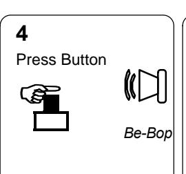
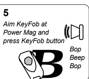
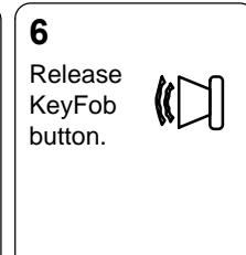
Sequentially Programming Additional KeyFobs
Once a KeyFob is programmed, using the advanced programming procedure described above, additional KeyFobs may be enrolled sequentially by repeating step 5 (aim additional KeyFobs at the Power Mag and press the KeyFob button) to enroll it into the next sequential location. For example, if you had just enrolled KeyFob number 42, the next one would be enrolled as 43 and the next as 44 and so on. The sounder will acknowledge each additional KeyFob as described above. To program additional KeyFobs which are not sequential, repeat steps 1 - 6 above for each KeyFob.
At any time the complete KeyFob database and option programming may be erased by holding down the push button on the Mag lock PCB for 12 seconds (at the 3rd beep). This will completely erase the KeyFob database and then place the unit into the Auto Enrollment mode described above.
5 steady beeps indicate that you are about to program a KeyFob over a KeyFob which is currently enrolled.
5 beeps ending with a low note indicate that a programming error has occurred.
System Option Programming
The RR-PM1200 can be configured to provide a variety of system options. The same method used in the Advanced programming of KeyFobs is used for the programming of system options.
- Unlock Power Mag with valid KeyFob
- Open Door
- Remove Cover from Power Mag Wiring Bay
- Locate the Rotary Dial Switch and Push Button on the Power Mag circuit board.
- Press and Hold Power Mag push button until 1st beep.
- 1 Turn Rotary Dial Switch to the character representing the 1st digit of the System Option to be programmed.
- 2 Press the circuit board Push Button (the sounder will beep)
- 3 Turn Switch to the character representing the 2nd digit of the System Option to be programmed.
- 4 Press the circuit board Push Button (the sounder will beep, followed by a three beep acknowledgment).
- 5 When programming is complete, press and hold PGM Push button for 5 seconds to exit program mode.
| em Option Programming | Commands | |
|---|---|---|
| Passa | ge Options: | |
| АА | Door Ajar OFF (default) | If door ajar is enabled, the Power Mag alarm will sound if the door is held open more than 20 |
| ΑВ | Door Ajar ON | seconds. |
| A C | Smart Pass OFF | After the Power Mag is released by KeyFob or the remote switch Smart Pass will, if enabled, |
| A D | Smart Pass ON (default) | automatically re-lock the Power Mag the instant the door is closed. |
| ВЕ | Chime OFF (default) | While in Passage Mode, the Power Mag will emit a chime tone each time the door is opened. |
| BF | Chime ON | See Passage Mode (option BD) |
| DΑ | Pass Time: 5 Sec. | Pass Time is the duration the door will remain unlocked after activation of a KeyFob or the |
| DΒ | Pass Time: 10 Sec. | remote release. |
| DC | Pass Time: 15 Sec. (default) | |
| D D | Pass Time Tone ON (default) | If Pass Time Tone is enabled, the Power Mag sounder will buzz for 2 seconds at the beginning |
| DΕ | Pass Time Tone OFF | of pass time. |
| DF | Pass Time on Power-up ON | Pass time may be initiated by momentarily removing power. This option is intended to allow |
| ΑE | Pass Time on Power-up OFF | control from an outside source, such as a request to exit device or an access control panel. |
| Remot | te Switch Input Options: | |
| ВА | Door Bell | A momentary short on the Remote Switch Input will cause the Power Mag sounder to emit a "ding -dong" door bell chime. |
| ВВ | Disabled (default) | Disabled - Shorting the Remote Switch Input will have no effect on system operation. |
| ВС | Remote Release | A momentary short on the Remote Switch Input will cause the Power Mag to unlock for the programmed Pass Time (see Pass Time options) |
| B D | Passage Mode | The door will remain in Passage Mode (unlocked) as long as the Remote Switch Input is shorted. |
| Auxilia | ary Relay Options: | |
| C A | Activate during pass time | The auxiliary relay will activate during Unlock time or passage mode. |
| СВ | Activate on power fail. | While the system is under power, the Aux. Relay will remain engaged. In the event of a power failure, the relay will de-energize. This can be used for activating emergency lighting, etc. |
| СС | Disabled (default) | |
| C D | Activate on Remote Input | The Auxiliary Relay will remain active as long as the Remote Switch Input is shorted. |
| CE | Follows door position | Auxiliary relay follows door position - Door open - Aux. relay on, Door closed - Aux relay off. |
| CF | Follows door ajar alarm | Auxiliary relay follows door ajar alarm. The relay will activate when the door ajar alarm sounds and will restore when door is closed. This option may be used to activate 24 hour zone on alarm system |
| Delete | KeyFob Options: | · · · · · · · · · · · · · · · · · · · |
| FE |
Remove KeyFob by User
Number |
Remove KeyFobs assigned to the following User Number(s) - used to remove a single KeyFo or a sequential block of KeyFobs. [F] [E] [First KeyFob address] [Last KeyFob address] Example 1: Remove KeyFobs 20 through 29: [F] [E] [2] [0] [2] [9] Example 2: Remove KeyFob 45: [F] [E] [4] [5] [4] [5] |
| FF | Remove KeyFob by KeyFob activation | Use this option to remove a KeyFob in your possession. Activate system option F F, aim KeyFob at Power Mag and press KeyFob button. If the sounder chirps, KeyFob is not programmed in database |
| System Option Programming Commands | |||
|---|---|---|---|
| System Related Options: | |||
| A E | Tone on power up OFF | The Power Mag can be configured to emit a 2 second tone each time it is powered up. | |
| A F | Tone on Power-up ON (default) (programming AE or AF will disable DF- Pass Time on Power-up) | ||
| F C | Adjust door test down | Physical installation parameters such as the construction of the door and jamb may require | |
| F D | Adjust door test up |
that the internal constants be adjusted should the Power Mag fail to detect when the door has
been opened. |
|
Example 1: Remove KeyFob from system (option FF)
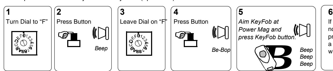
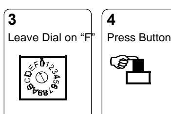
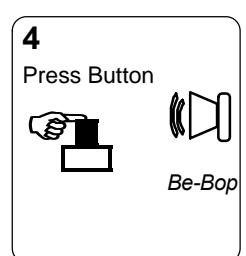
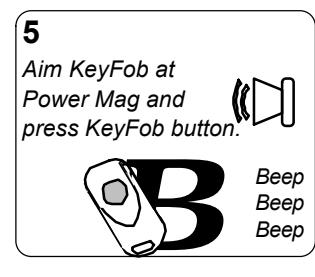
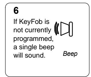
Example 2: Program the Aux. relay to follow door position (option CE)
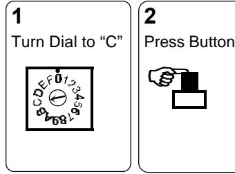
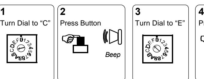
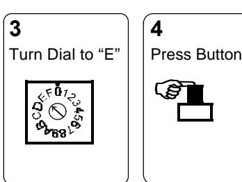
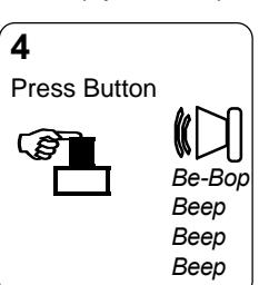
NOTE: If an existing KeyFob is to be re-programmed as a Passage Mode enabled KeyFob (address 90-99), be sure to first remove it from its original address. Follow the instructions above "Remove KeyFob from system" and then re-enroll as a Passage Mode KeyFob.
Advanced Features
Passage Mode
The Power Mag can be set to a Passage Mode (unlocked) state, where full access through the door is permitted. Passage Mode can be enabled only by KeyFobs mapped to addresses 90 through 99 or by the Remote Switch Input (if programmed for Passage - command BD). While these KeyFobs operate normally, granting access when the KeyFob button is pressed, they can also initiate Passage Mode through a special Hold Down feature. Passage Mode is initiated by aiming the KeyFob at the Power Mag and holding down the button for 5 seconds. The sounder will beep 3 times to acknowledge Passage Mode. To disable passage mode, aim any one of the Passage Mode enabled KeyFobs at the Power Mag and slowly press the button twice. If the KeyFob button is only pressed once, a Lock Down mode is enabled. (see Lock Down).
Lock Down Mode
Lock Down Mode allows a door in Passage Mode to be quickly locked in the event of a panic condition. A single button press from any Passage Mode authorized KeyFob while Passage Mode is active will put the door into a 3 minute Lock Down mode. Once in the Lock Down mode, ONLY the KeyFob which initiated Lock Down may be used to disable it, with another single button press, which will return the Power Mag to the standard locked mode. To insure that the door is not inadvertently opened while in Lock Down, all other KeyFobs except for the one which initiated Lock Down are disabled for the 3 minute duration.
Smart Pass
Smart Passage allows the Power Mag to automatically re-lock the door as soon as it senses that it has closed, even if the Pass Time has not expired. This will allow the lock to be programmed for the maximum Pass Time of 15 seconds (default) without the fear that an intruder will re-open the door and slip in behind a valid user. (programmable - command AD)
Door Ajar Alarm
Door Ajar Alarm will prompt the Power Mag to go into alarm if it senses that the door has been held open for 20 seconds. When in alarm, it may be silenced by closing the door. (programmable - command AB)
Remote Release
The Remote Switch Input can be programmed to allow a push of a momentary button to permit passage for the programmed Pass Time duration. (programmable - command BC)
Typical Applications
Using the Remote Switch Input as a "Request to Exit" input and configuring low voltage lighting to follow lock activity.
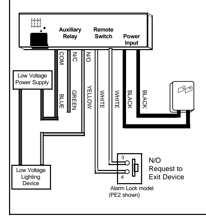
Required Programming:
- Enable Remote Switch Input Option: BC-Remote Release
- Set Appropriate Pass Time in Passage Options (5,10 or 15 seconds)
- Enable Appropriate Auxiliary Relay Option to activate lighting upon lock activity: (CA, CB, CD, CE and/or CF)
Operation:
- Rather that requiring the User to use the Keyfob to exit, a request to exit device such as a motion sensor or push button device may be used to initiate passage.
- Low voltage light may be configured to follow lock activity to provide lighting while door is open, during AC power failure, etc..
Using the Remote Switch Input as a door bell, interrupting power for "Request to Exit" and supervising the Power Mag for a "Door opened" condition through a dedicated zone on a burglar alarm control panel.
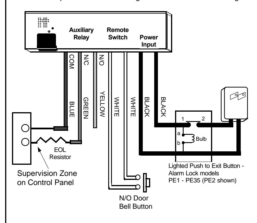
Required Programming:
- Enable Pass Time on Power-Up (DF)
- Set Appropriate Pass Time in Passage Options (5,10 or 15 seconds)
- Enable Auxiliary Relay Follow Door Position (CE)
- Enable Door Bell on Remote Switch Input (BA)
Operation:
- Interrupting Power Mag Power is used for Request to Exit which allows the Remote Input to be used for other applications.
- The Remote Input is used to activate a door bell which will cause the Power Mag's sounder to sound a "Ding Dong" door bell sound when pushed.
- The Auxiliary Relay is used to indicate a Door Opened Condition to a Burglar alarm control panel.
Typical Applications
Interfacing to an access control system to allow card reader access in addition to keyfob access.
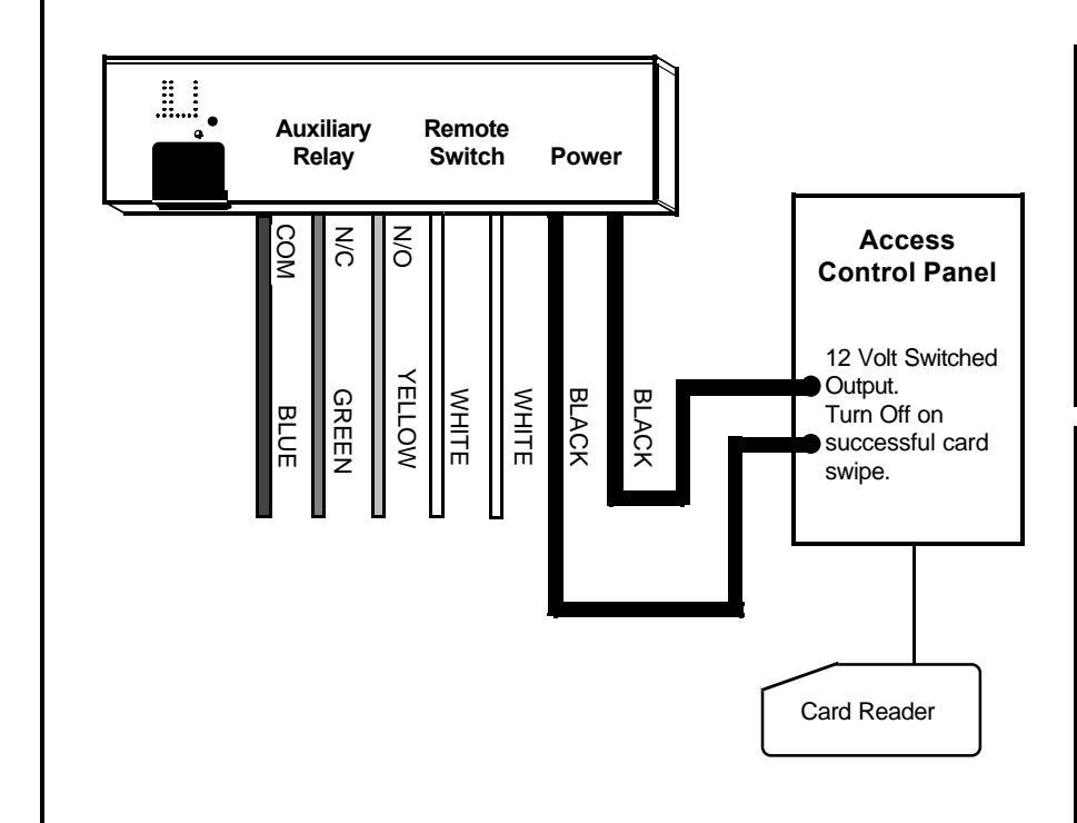
Required Programming:
• Set Appropriate Pass Time in Passage Options (5,10 or 15 seconds) (default Pass time = 15 sec.)
Operation:
• The Access Control panel interrupts Power Mag Power upon a successful card swipe, initiating Pass Time.
Using a normally open toggle switch to provide passage mode and the Auxiliary Output to trigger a recording system to record activity only when door is opened.
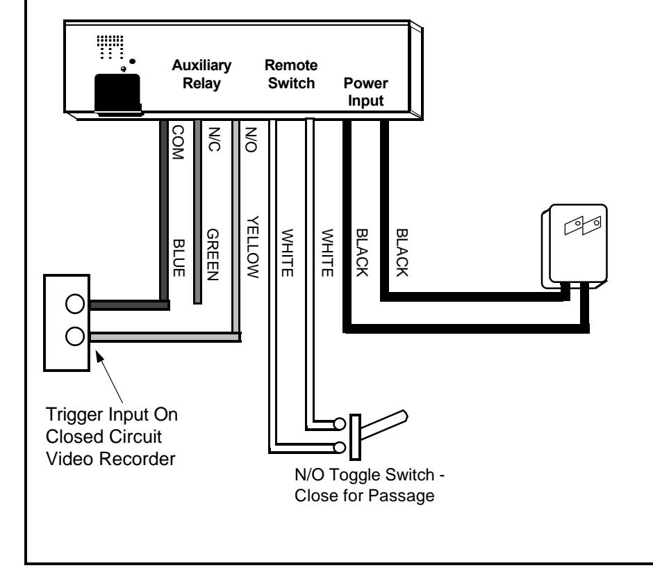
Required Programming:
- Enable Passage on Remote Switch input short.(BD)
- Enable Auxiliary Relay follows door position (CE)
- Enable Chime Mode (BF)
Operation:
- The Remote Input is used with a toggle switch to activate passage Mode.
- The Auxiliary Relay is used to indicate a "Door Open" condition to a closed circuit recorder which enables it to recorder door activity only when opened.
- Chime Mode enables the Power Mag internal sounder to indicate that the door has opened.
| SYSTEM USER DATABASE RECORD LOG | ||||
|---|---|---|---|---|
| USER # | USER NAME | USER # | USER NAME | |
| 00 | 25 | |||
| 01 | 26 | |||
| 02 | 27 | |||
| 03 | 28 | |||
| 04 | 29 | |||
| 05 | 30 | |||
| 06 | 31 | |||
| 07 | 32 | |||
| 08 | 33 | |||
| 09 | 34 | |||
| 10 | 35 | |||
| 11 | 36 | |||
| 12 | 37 | |||
| 13 | 38 | |||
| 14 | 39 | |||
| 15 | 40 | |||
| 16 | 41 | |||
| 17 | 42 | |||
| 18 | 43 | |||
| 19 | 44 | |||
| 20 | 45 | |||
| 21 | 46 | |||
| 22 | 47 | |||
| 23 | 48 | |||
| 24 | 49 | |||
| SYSTEM USER DATABASE RECORD LOG | ||||
|---|---|---|---|---|
| USER # | USER NAME | USER # | USER NAME | |
| 50 | 75 | |||
| 51 | 76 | |||
| 52 | 77 | |||
| 53 | 78 | |||
| 54 | 79 | |||
| 55 | 80 | |||
| 56 | 81 | |||
| 57 | 82 | |||
| 58 | 83 | |||
| 59 | 84 | |||
| 60 | 85 | |||
| 61 | 86 | |||
| 62 | 87 | |||
| 63 | 88 | |||
| 64 | 89 | |||
| 65 | 90 | |||
| 66 | 91 | |||
| 67 | 92 | |||
| 68 | 93 | |||
| 69 | 94 | |||
| 70 | 95 | |||
| 71 | 96 | |||
| 72 | 97 | |||
| 73 | 98 | |||
| 74 | 99 | |||
ALARM LOCK LIMITED WARRANTY
ALARM LOCK SECURITY SYSTEMS, INC. (ALARM LOCK) warrants its products to be free from manufacturing defects in materials and workmanship for 24 months following the date of manufacture. ALARM LOCK will, within said period, at its option, repair or replace any product failing to operate correctly without charge to the original purchaser or user.
This warranty shall not apply to any equipment, or any part thereof, which has been repaired by others, improperly installed, improperly used, abused, altered, damaged, subjected to acts of God, or on which any serial numbers have been altered, defaced or removed. Seller will not be responsible for any dismantling or reinstallation charges.
THERE ARE NO WARRANTIES, EXPRESS OR IMPLIED, WHICH EXTEND BEYOND THE DESCRIPTION ON THE FACE HEREOF. THERE IS NO EXPRESS OR IMPLIED WARRANTY OF MERCHANTABILITY OR A WARRANTY OF FITNESS FOR A PARTICULAR PURPOSE. ADDITIONALLY, THIS WARRANTY IS IN LIEU OF ALL OTHER OBLIGATIONS OR LIABILITIES ON THE PART OF ALARM LOCK.
Any action for breach of warranty, including but not limited to any implied warranty of merchantability, must be brought within the six months following the end of the warranty period.
IN NO CASE SHALL ALARM LOCK BE LIABLE TO ANYONE FOR ANY CONSEQUENTIAL OR INCIDENTAL DAMAGES FOR BREACH OF THIS OR ANY OTHER WARRANTY, EXPRESS OR IMPLIED, EVEN IF THE LOSS OR DAMAGE IS CAUSED BY THE SELLER'S OWN NEGLIGENCE OR FAULT.
In case of defect, contact the security professional who installed and maintains your security system. In order to exercise the warranty, the product must be returned by the security professional, shipping costs prepaid and insured to ALARM LOCK. After repair or replacement, ALARM LOCK assumes the cost of returning products under warranty. ALARM LOCK shall have no obligation under this warranty, or otherwise, if the product has been repaired by others, improperly installed, improperly used, abused, altered, damaged, subjected to accident, nuisance, flood, fire or acts of God, or on which any serial numbers have been altered, defaced or removed. ALARM LOCK will not be responsible for any dismantling, reassembly or reinstallation charges.
This warranty contains the entire warranty. It is the sole warranty and any prior agreements or representations, whether oral or written, are either merged herein or are expressly canceled. ALARM
LOCK neither assumes, nor authorizes any other person purporting to act on its behalf to modify, to change, or to assume for it, any other warranty or liability concerning its products.
In no event shall ALARM LOCK be liable for an amount in excess of ALARM LOCK's original selling price of the product, for any loss or damage, whether direct, indirect, incidental, consequential, or otherwise arising out of any failure of the product. Seller's warranty, as hereinabove set forth, shall not be enlarged, diminished or affected by and no obligation or liability shall arise or grow out of Seller's rendering of technical advice or service in connection with Buyer's order of the goods furnished hereunder.
ALARM LOCK RECOMMENDS THAT THE ENTIRE SYSTEM BE COMPLETELY TESTED WEEKLY.
Warning: Despite frequent testing, and due to, but not limited to, any or all of the following; criminal tampering, electrical or communications disruption, it is possible for the system to fail to perform as expected. ALARM LOCK does not represent that the product/ system may not be compromised or circumvented; or that the product or system will prevent any personal injury or property loss by burglary, robbery, fire or otherwise; nor that the product or system will in all cases provide adequate warning or protection. A properly installed and maintained alarm may only reduce risk of burglary, robbery, fire or otherwise but it is not insurance or a guarantee that these events will not occur. CONSEQUENTLY, SELLER SHALL HAVE NO LIABILITY FOR ANY PERSONAL INJURY, PROPERTY DAMAGE, OR OTHER LOSS BASED ON A CLAIM THE PRODUCT FAILED TO GIVE WARNING. Therefore, the installer should in turn advise the consumer to take any and all precautions for his or her safety including, but not limited to, fleeing the premises and calling police or fire department, in order to mitigate the possibilities of harm and/or damage.
ALARM LOCK is not an insurer of either the property or safety of the user's family or employees, and limits its liability for any loss or damage including incidental or consequential damages to ALARM LOCK's original selling price of the product regardless of the cause of such loss or damage.
Some states do not allow limitations on how long an implied warranty lasts or do not allow the exclusion or limitation of incidental or consequential damages, or differentiate in their treatment of limitations of liability for ordinary or gross negligence, so the above limitations or exclusions may not apply to you. This Warranty gives you specific legal rights and you may also have other rights which vary from state to state.