Alarm Lock NETPDK NETDK Networx Panel Programming Instructions
Open the original PDF document
View PDF

345 Bayview Avenue, Amityville, New York 11701 For Sales and Repairs 1-800-ALA-LOCK For Technical Service 1-800-645-9440 or visit us at http://tech.napcosecurity.com/
(Note: Technical Service is for security professionals only) Publicly traded on NASDAQ Symbol: NSSC
© ALARM LOCK 2017
Trilogy NETWORXPANEL Programming Instructions
WI1855C 2/17
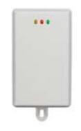
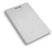
PROXIMITY CARD AL-IM2-PIE PLUG-IN EXPANDER MODULE
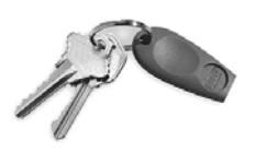
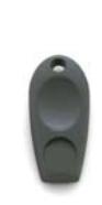
PROXIMITY KEYFOB
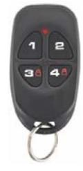
RR-4BKEYFOB
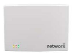
AL-IME2-EXP AL-IM2-80211 AL-IME2 AL-IME2-POE
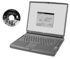
DL-WINDOWS PROGRAMMING SOFTWARE
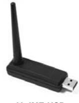
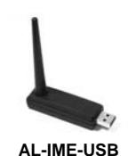
AL-IME-USB GATEWAY MODULE
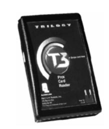
AL-PRE PROXIMITY CARD READER / ENROLLER
NETWORXPANEL & NETPDK / NETDK KEYPADS
THE ALARM LOCK TRILOGY SERIES STAND-ALONE AND NETWORK PROGRAMMABLE ACCESS CONTROL SYSTEM IS A SERIES OF STATE-OF-THE-ART WIRELESS AND KEYPAD-ENTRY PROGRAMMABLE SECURITY DEVICES.
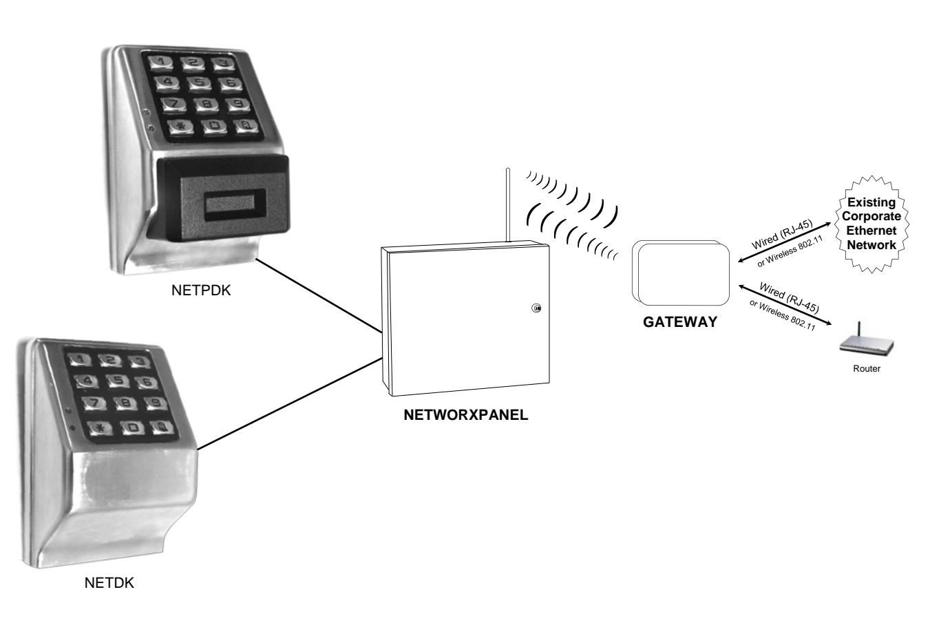
The NETDK and NETPDK (with proximity card reader) are secured single-door or double-door digital keypads for use within the wireless Networx™ system. One or two keypads can be wired to the dedicated NETWORXPANEL control panel to provide controlled access to a door by releasing a locking device (such as a magnetic lock or electric door strike) when a proper User Code (and/or a proximity credential to the NETPDK) is presented. The NETWORXPANEL inputs support two of any combination of NETDK or NETPDK keypads, PLUS up to two Wiegand devices. If a special "Two-Door Mode" is programmed, up to two doors can be controlled using two keypads, with one keypad (designated as "primary") controlling door #1 and another keypad (designated as "secondary") controlling door #2. To set up "Two-Door Mode", see the NETWORXPANEL installation instructions (WI1856) for complete wiring and other information.
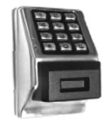
NETPDK
NETDK
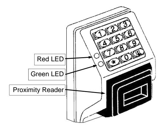
Both the NETDK and NETPDK operate identically (the only difference being the NETPDK includes an integral HID compatible ProxCard® proximity reader), therefore this one manual includes keypad programming instructions for both keypads. Be aware that all references to "Prox" or the proximity reader in this manual apply ONLY to the NETPDK model . In addition, although the NETPDK and NETDK keypads do not possess the internal hardware of a lockset, for the purposes of this manual, the term "lock" may be used to describe either keypad and/or other wireless locksets within the wireless Networx system. The word "system" may be used to describe the NETWORXPANEL and its keypads, Wiegand and controlled door locking devices. The specific model name "NETPDK" or "NETDK" will be used as needed.
NETWORXPANEL Control Panel
This manual describes a variety of features that can be programmed into and stored within the NETWORXPANEL memory; these features can be programmed using the NETDK or NETPDK keypad buttons or from a DL-Windows equipped computer through the NETWORXPAN-EL's radio link.
Wireless Network and DL-Windows
If your Networx wireless network is not yet set up, you can add Users and program other features using the keypad as a temporary convenience to allow the lock to be put into use before installing the wireless network. Be aware that all programming added using the keypad cannot be retrieved into DL-Windows, so if you decide to start programming using the keypad, we recommend you keep hardcopy records (in a secure location) of all Users, User Codes, and any proximity cards that may have been programmed. Keeping these hardcopy records will save time because after the wireless network is set up, all programming added via the keypad can easily be re-added to DL-Windows and downloaded back to the lock(s). Note: Within DL-Windows, select lock type "NETWX PNL" for all NETPDK or NETDK keypads. There is no need to distinguish between models, because the NETWORXPANEL will auto-detect the presence of the NETPDK's Proximity reader. DL-Windows always assumes the NETWORXPANEL keypad is a NETPDK, therefore proximity card data may be added to DL-Windows and downloaded to the NETWORXPANEL, but if the only keypad wired is a NETDK, the NETWORXPANEL will ignore the proximity data.
Wiegand Devices
The NETWORXPANEL inputs support two of any combination of NETDK or NETPDK keypads, PLUS up to two Wiegand devices. In most cases, features may also be programmed using Wiegand devices that are equipped with their own keypads; however, be aware that some Wiegand device designs may interfere with the smooth ability to program the system. For ease of use, we therefore recommend all programming be performed using either the NETDK / NETPDK keypads or with DL-Windows through the wireless Networx™ system. For DL-Windows user operation instructions, see OI382; for Networx configuration and setup instructions, see OI383. For NETWORXPAN-EL installation instructions, see WI1856.
Version 2 Gateways
The AL-IM2-80211 , AL-IME2 and the AL-IME2-POE "version 2" Gateways (notice the "2" in the model name) are the next generation of Networx Gateways. The "version 2" models are virtually the same as the original "version 1" Gateways, but have the added ability to expand your system with up to 7 Expanders. Note: Although the version 2 AL-IME2 Gateways and AL-IME2-EXP Expanders CAN be mixed into an existing system that includes older "non-version 2" Gateways, at least one new AL-IME2 Gateway must be up and running before an AL-IME2-EXP Expander will function (AL-IME2-EXP Expanders cannot communicate with older "non-version 2" Gateways). Important: DL-Windows V5.4 or later is required to support version 2 Gateways and Expanders. Note: The AL-IME2-POE Gateway is compatible with Alarm Lock and Continental Access products. Refer to the documentation supplied with your software for integration details.
Table of Contents
| Features 3 | Programming Functions Overview 13 |
|---|---|
| Supported Products 4 | Programming Functions 14-28 |
| General Overview 5 | Function 67 Features 22-24 |
| Terminology Used in this Manual 6 | Groups and Scheduled Group 1 Examples 29-30 |
| Programming Levels 8 | Programming Record Sheet 31 |
| Conventions Used in this Manual 9 | User Code Record Sheet 32 |
| LED and Sounder Indicators 9 | Schedule Record Sheet 33 |
| Quick Start 10 | Glossary 34-35 |
| Testing the Codes Entered 12 | Warranty 36 |
NETWORXPANEL Features
Audit Trail
- 40,000 Event Capacity
- Entries Logged with Time and Date
- Critical Programming Events Logged
- Uploadable using Alarm Lock's DL-Windows software (see page 5)
Features
- "Two-Door Mode": Up to two doors can be controlled (see Function 67, feature 13 on page 22)
- Keypad Lockout (see page 21, Functions 60-61)
- Non-Volatile (Fixed) Memory
- Real-Time Clock (within one second accuracy) (see page 19, Functions 43-44)
- Programmable Relay (see page 22)
- Visual and Audible Keypad Feedback (see page 9)
- Battery Status Monitor (see page 9)
- Door Status Monitoring (see page 22, "Relay on Door Ajar")
Scheduling
- 500 Scheduled Events (see pages 25-28)
- Automated Unlock/Lock
- Enable/Disable Users (see page 15, Function 3)
- Enable/Disable Groups (see page 16)
- Four "Quick Schedules" (contains 4 most common schedules) (see page 26)
- Real-time clock and calendar (see page 19)
- Programmable Timeout Functions (see page 15-17)
User Access Methods
- Keypad Entered User Codes (see pages 11-12, 14)
- ProxCard® and ProxKey® Keyfob* (see page 11)
- User Code and ProxCard® (For highest security)* (see page 11)
- Batch Enroll Quickly and easily enroll multiple ProxCards® and ProxKey® keyfobs without the use of a PC (see page 11)*.
User Features
- 5000 Users (see pages 11-12, 14)
- 5 Pre-defined Administration User Levels including Master , Installer , Manager , Supervisor and Basic User Codes (see page 8)
- User Code Lengths from 3-6 digits
- Service Code ("One-Time-Only" Code) (see page 7)
- User Lockout Mode (see page 15, Function 6)
- Users Assignable to 4 Groups (see page 29)
- Ambush Function (see page 21, Function 66)
- Guard Tour Code (see page 7)
- Emergency Commands (see page 7)
Keypad and Computer Programming
- All programming may be performed manually from the keypad, or from a PC using Alarm Lock's DL-Windows Software (see page 7)
- Support for "version 2" Gateways and Expanders (see OI383 for more information)




Supported Products
AL-IM2 SERIES WI-FI Gateway Modules
The NETWORXPANEL contains a radio that transmits and receives data--via a private wireless signal--to an intermediate device called a Gateway module. In turn, this Gateway module is connected (either wirelessly or wired) to a computer network such as a LAN or corporate Intranet. A Windows PC connected to this network can control and program all Networx series door locks by the use of the DL-Windows software (see OI382 and OI383). With access rights to the software, one computer--or several--can control the software and consequently can control the devices in the system. Note: See page 3 for an explanation of "VERSION 2". Several device models are available:


connects directly to a network using a standard RJ-45 Ethernet cable. This model has one antenna used

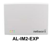
or greater in your Windows laptop or PC, quickly and effortlessly creating a wireless connection to your Networx series door locks. Requires DL-Windows v5.3.2 or higher. Note: Only "Local" Emergency Commands are supported when using an AL-IME-USB Gateway. See User's Guide Ol386. • AL-IME2-EXP Expanders extend the coverage area of AL-IME2 series Gateways, allowing control of up to its rated maximum of 63 Networx locks per Gateway. Installation is simple, as Expanders only
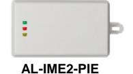
• AL-IME2-EXP Expanders extend the coverage area of AL-IME2 series Gateways, allowing control of up to its rated maximum of 63 Networx locks per Gateway. Installation is simple, as Expanders only require a connection to 12VDC power supply. AL-IME2-EXP Expanders are cost-effective, easier to wire than conventional Gateways, and feature a simplified 'Plug and Play' setup where the Networx system automatically identifies all newly powered Expanders and quickly determines the best wireless signal pathways. Up to 7 Expanders can be added to one AL-IME2 series Gateway. For more information about the AL-IME2-EXP, see WI2156. The easy to install AL-IME2-PIE Plug-In Expander can simply be powered by any ordinary 120VAC wall outlet. See OI391 and WI2219 for details.
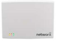
AL-IM2-80211 AL-IME2 AL-IME2POE
, ._ ....<u>_</u> _, ..
Gz.
Proximity Card Reader/Enroller (AL-PRE)
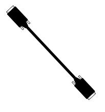
An AL-PRE is used to quickly enroll multiple proximity cards and keyfobs into DL-Windows without the need to manually type proximity data. Use the supplied 9-pin DB9 to DB9 serial cable (see below for description) to connect the AL-PRE to your computer's serial COM port. Compatible with most HID ProxCards® and ProxKey® keyfobs (37 bits or less). For NETPDK models with integral proximity readers only.

Compatible with most HID ProxCards® and ProxKey® keyfobs (37 bits or less). For NETPDK models with integral proximity readers only.
DB9 to DB9 Serial Cable
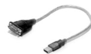
Enroll proximity cards and keyfobs quickly by using the AL-PRE to DL-Windows by connecting one end of this 9-pin male DB9 to female DB9 serial cable to the AL-PRE and the other end to your computer's serial COM port. If your computer does not have a serial COM port (DB-9 male) available, use the USB to RS-232 Cable described below.
USB to RS-232 Cable
If your computer does not have a serial COM port (DB-9 male) available, you can plug your AL-PCI2 cable into a special USB to RS-232 cable. Order part MX1130 for the USB to RS-232 cable only.
General Overview
Why use User Codes?
With ordinary door locks, the need to make physical copies of metal keys and distributing them can be a huge organizational and financial task -- and what will you do if someone causes a security breach by accidentally losing their key?
The answer lies in the advantage of "firmware". The firmware inside the NETWORXPANEL can be programmed (and reprogrammed again and again) to suit your changing requirements. No more metal keys to distribute...instead, distribute User Codes -- and delete them from the firmware when needed. A User Code is the firmware equivalent of a metal key--it is a series of numeric button-presses at the NETPDK or NETDK keypad to allow (for example) passage through a door.
Preparing to Program User Codes
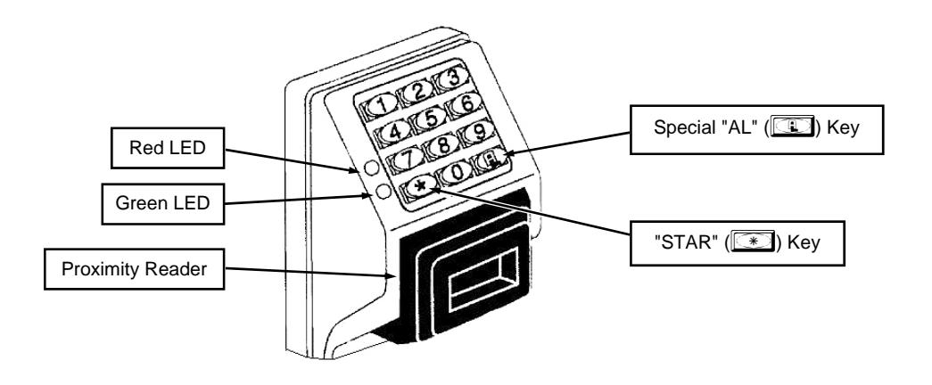
The NETPDK and NETDK keypads each contain 12 buttons, numbers 1 through 9 plus zero, a star button ( : ) and a special "AL" button ( ; ). You can use a NETPDK or NETDK keypad to program your system, or you can use a computer program called DL-Windows that can be configured to program your system wirelessly. This guide will show you how to program your NETWORXPANEL using the NETPDK or NETDK keypad, without DL-Windows. (For more information about DL-Windows, see User Guides OI382; for information about using DL-Windows within the Networx wireless system, see OI383).
After all the door lock hardware is installed and the keypads are mounted, programming your system begins after the NETWORX-PANEL is powered and its memory is cleared (see WI1856 for the exact procedure). Before you can program using the keypad, you must first enter something called "Program Mode".
What is Program Mode?
The Networx system has two "modes": "Normal Mode" and "Program Mode". When you want to make changes to the system programming (such as adding the many features detailed in this manual), enter "Program Mode". When programming is finished and wish to put the Networx system into use, exit "Program Mode" to enter "Normal Mode".
Enter Program Mode by pressing the Master Code set at the factory (then wait for the green light and press ; until multiple beeps are heard). The Master Code is basically a secret 6-digit "passcode" that allows you to enter Program Mode. But since all NETWORXPANEL control panels are identical and leave the factory with the same Master Code, this factory Master Code is therefore not very secret--and should be changed to your own personal Master Code. This way, only YOU can enter Program Mode and make changes to the programming.
Once the new Master Code is set , then you can continue with the Quick Start procedure and set the weekday, date and time. After this, you can start entering User Codes for people to use. Programming changes are organized by their Function Number. Want to change the date? Use Function Number 38. Want to add a User Code? Use Function Number 2. There are 99 Functions in total, some that you may use often, and others that you may never need.
Notice that when you make programming changes, there is a consistent 5-step pattern: (1) Enter Program Mode (2) Press ; followed by the Function # (3) Press ; and enter data (4) Press : to end (5) Exit Program Mode to put the system into use.
Turn the page and learn about the special terminology used with your system, then use the Quick Start procedure on page 10 to help you get up and running.
Terminology Used in this Manual
Wired to the dedicated NETWORXPANEL control panel, the NETPDK and NETDK are secured digital keypads for use within the wireless Networx™ system (see WI1856 for more information).
What is a Lock Profile ?
A Lock Profile contains the instructions that the system uses to perform its various functions. These instructions are stored in memory within the NETWORXPANEL PC board circuitry. You can use the keypad to make changes to the programming or you can use DL-Windows (defined below) to create a Lock Profile on your computer, and then transfer and store the Profile within the NETWORXPANEL memory. The Lock Profile is essentially a computer database file that maintains User Codes, feature settings, schedules, audit trails, etc. Using DL-Windows, Lock Profiles can be created with default information, edited on your PC, and then sent to (and even received from) the NETWORXPANEL. The Lock Profile consists of 4 general areas: User Codes , Functions , Time Zones , and Schedules , all defined below:
What are User Codes ?
Also called User Access Codes or PIN No. Codes , User Codes are numbers the User "presses" into the keypad buttons to trigger a relay within the NETWORXPANEL to release a locking device such as a magnetic lock or electric door strike.
What are Functions ?
The system supports many options. Using the keypad or DL-Windows software, you can select the options you wish to activate, such as if the system will automatically adjust for Daylight Saving Time, or if User Codes should be disabled during Global Lock Down (see " How do the Emergency Commands work? ", below).
What is a TimeZone ?
Certain system events (for example, "Enable Passage") can be programmed to occur at certain times. It is these times (for example, "every Tuesday at 5PM") that are referred to as TimeZones . TimeZones can be created manually through the keypad. In DL-Windows, you can use the Schedule-TimeZone screen to create these TimeZones, and once created, you can link system events to these TimeZones.
What is a Schedule ?
A Schedule can be maintained in which certain system events (for example, "Enable Passage") can occur automatically. For example, you can program the NETWORXPANEL to allow Groups of Users (with their User Codes) access ONLY during specific business hours. With another example, you can program another NET-WORXPANEL to unlock a door at 9AM, lock at noon for lunch, unlock at 1PM, and lock again at 5PM--every weekday. As you can see, many different combinations of Schedules can be created. First you create TimeZones (see above), then select events and link them to your TimeZones (using the Schedule-TimeZone screen in DL-Windows). When finished, you can view your schedule in the DL-Windows Schedule View screen.
What is a User ?
A User is a person who simply uses or is authorized to make programming changes to the system. A User can be anyone--from a one-time visitor (who will likely have no authority to make system changes) to the owner of the building in which the system is installed (likely to have total authority to make changes). The system can hold up to 5000 Users in memory, and each User possesses a pre-defined level of authority--a Programming Level --as to their ability to use or make changes to the system.
What is a Programming Level ?
The Programming Level defines the range of programming tasks a User is allowed to perform. The higher the Level, the more programming tasks the User is allowed (with Master allowing ALL tasks).
Note: Since the Programming Level is closely associated with the type of User and their abilities, a User who holds a certain Programming Level is sometimes referred to by their " User Type ".
For example, the NETWORXPANEL can hold up to 5000 Users in its programming memory, and each User is associated with a User Number (see definition of "User Number" below) and therefore a specific Programming Level, as follows:
Master: Always associated with User Number 1. Is always enabled and can program all functions. (Abbreviated as Programming Level = M).
Installer: Always associated with User Numbers 2 and 3. Can program all functions except changing the Master Code. (Abbreviated as Programming Level = 4).
Manager: Always associated with User Numbers 4, 5, and 6. Can program all functions except functions relating to the system configuration. (Abbreviated as Programming Level = 3).
Supervisor: Always associated with User Numbers 7, 8 and 9. Can only program functions relating to day to day operation. (Abbreviated as Programming Level = 2).
Print Only Users: In previous versions of the ALARM LOCK Trilogy series models, Print Only Users were always associated with User Numbers 10 & 11 and were restricted to printing event logs only, using a special AL-IR1 handheld printer. With the NETPDK and/or NETDK no longer allowing/requiring the use of this AL-IR1 printer, Print Only Users are also no longer allowed/ required. Although the attributes of User Numbers 10 and 11 have been changed to replicate those of "Basic Users", to ensure compatibility with previous model versions, the use of User Number 10 and User Number 11 is not recommended.
Basic Users: Always associated with User Number 12 and higher (except 297-300). No programming ability allowed. In most cases, most Users are Basic Users , who are simply given their own individual User Codes and are only allowed to "unlock" the system (to allow passage) when needed.
Programming Levels are hierarchical--higher Levels are allowed to perform anything the Levels below them can. For example, if you are a Manager , you are allowed to perform all tasks that Supervisors and Basic Users can perform in addition to those tasks allowed for Managers (Level 3).
What is the Minimum Required Program Level ?
This Programming Level abbreviation is the minimum Programming Level required to program the particular Function. (The higher the Level number, the more programming tasks the User is allowed, with Master allowing all tasks).
In this manual, Programming Levels are abbreviated as follows: M = Master, 4 = Installer, 3 = Manager, 2 = Supervisor. Levels are hierarchical, with higher levels being allowed to do anything the levels below them can do. Therefore Level 4 is "higher" than level 3. See the chart on page 8 for more information.
What is a User Number?
("User Number" = "Location Number" = "User Location" = "Slot") User Numbers are used within each individual NETWORXPANEL only. The User Number determines the Programming Level for each User. The system can hold up to 5000 User Codes in its programming memory. These 5000 User Codes can be thought of as a numbered list from 1 to 5000 (from "User Number 1" through
Terminology Used in this Manual (cont'd)
"User Number 5000"). Therefore, where a User Code is located in this list will determine its Programming Level, and therefore the User's programming abilities. Because the location within this list is the determining factor, the terms User Number , User Location and Location Number are often used interchangeably. In some DL-Windows screens, the word "Slot" is also used. They all mean the same thing. Example: John Smith is assigned a User Code located at User Number 452 (or "User 452"). Because John's User Code is located at User Number 452, he is a "Basic User", and thus is unable to perform programming tasks. If his User Code was assigned to User Number 4, he would be permitted those programming tasks allowed for "Managers". See the chart on page 8 to help visualize this User Number list.
What is a Group ?
With many applications, it is convenient for large numbers of similar Users to be grouped together. Placing Users into Groups (by assigning them specific User Numbers) allows large numbers of Users to be controlled all at once rather than individually--saving time and effort. Groups are controlled via schedules, and a typical example involves enabling or disabling a Group at a certain time. Default Group associations are specified in the table on page 8. For example, if you wish to add a User to Group 1, assign this User a User Number between 51 and 100. These default Group associations can be changed if needed to allow Groups larger than the default number of 50 (by using keypad Function 35). (See page 16 for some Group function examples).
What is DL-Windows ?
DL-Windows is a computer program that allows you to program your ALARM LOCK security device. You do not need DL-Windows to program your system, but it makes programming much faster and easier. With DL-Windows, you can quickly create Lock Profiles (programs that make the system perform its many functions) add multiple User Codes, add proximity cards and keyfobs, retrieve event logs, create Schedules, etc. One benefit of DL-Windows is that it allows you to set up all programming in advance (on your computer), and then later send the information to the NETWORXPANEL at your convenience.
DL-Windows software allows you to upload and download programming features wirelessly using the Trilogy Networx™ system and a computer network. See OI383 for more information. Note: Within DL-Windows, select lock type "NETWX PNL" for all NETPDK or NETDK keypads.
How do the Emergency Commands work?
For use with all keypads enrolled into the Trilogy Networx™ wireless network, these wireless commands can be sent to all wireless locking devices in an Account during a crisis or other urgent situation. Any User Code can be programmed to allow the use of these Emergency Commands by simply adding that User Code to an "emergency function list" within DL-Windows (User Numbers 2-11 are automatically on this list). At any wireless keypad:
- Press an enabled User Code, then press 911 to issue " Global Lock Down ", to lock all doors in the Account;
- Press an enabled User Code, then press 000 to issue " Global Passage ", to unlock all doors in the Account;
- Press an enabled User Code, then press 123 to return all devices in the Account to "normal" (nonemergency) operation.
Note: 3 chirps sound after each emergency command entry.
See the DL-Windows User's Guide OI383, "Emergency Lock Down" for more information. Note: DL-Windows does not need to be running to allow these "Emergency" commands to be initiated; any wireless keypad can be used to disseminate these commands throughout the system. Note: If "Two-Door Mode" is enabled (Function 67, feature 13), both doors will be triggered.
Who are Users 297-300 ?
Users assigned to User Numbers 297, 298, 299 and 300 have special abilities, as follows:
User 297: Quick Enable User 300
User 297 possesses the unique ability to enable the User Code associated with User 300. User 297 does this by first entering their own User 297 User Code at the keypad. When User 300 subsequently enters their User 300 User Code , the keypad allows access (for one time) and then the User 300 User Code becomes disabled.
For example, you wish to allow one-time access to a temporary worker. Simply press the User 297 User Code at the NETPDK keypad. Later, when the temporary worker presses the User 300 User Code into the keypad, the User 300 User Code allows access (for one time only) and then becomes disabled. Later, if you wish to grant the temporary worker re-access, simply re-enter the User 297 User Code and the User 300 User Code will be reenabled (again for one time only). Note: From the factory, the User 300 User Code is blank; when the User 300 User Code is added, it is automatically enabled by default. In addition, each time features or Users are uploaded from DL-Windows to the NETWORXPANEL, the User 300 User Code is re-enabled for ALL keypads in the DL-Windows Account.
User 298: Reserved for Future Use
In previous versions of the ALARM LOCK Trilogy series model locksets, User Number 298 initiated the sending of data to or from a door lock, and a special "AL-PCI" cable was used to physically connect the door lock to a PC running DL-Windows. With the wireless NETWORXPANEL no longer requiring a wired connection, User Number 298 is consequently no longer required and has been removed as an active code. Note that the User 298 User Code does provide a "Guard Tour" type function (logging the Code entry with a time and date stamp in the Event Log / Audit Trail), but to ensure compatibility with previous Trilogy model versions, the use of User 298 is not recommended. Note: User 298 is not an "access code" (it is a "non-pass" code) and therefore does not allow passage through a protected door. See " User 299: Guard Tour Code " below.
User 299: Guard Tour Code
A Guard Tour Code is used to log the movement of a security guard as he or she makes rounds from one assigned guard tour station to the next. Entering the User 299 code provides precise verification and accountability of a guard's movements by logging the location with a time/date stamp in the Event Log (Audit Trail). Note: User 299 is not an "access code" (it is a "non-pass" code) and therefore does not allow the security guard to pass through a protected door.
User 300: One-Time Only Service Code
This is a One-Time Only Service User Code enabled by User 297. In addition, User Code 300 is sometimes used for guard tour duties. See " User 297: Quick Enable User 300 " , above.
Programming Levels
The Programming Level defines the range of programming tasks a User is allowed to perform. The higher the Level, the more programming tasks the User is allowed (with Master allowing ALL tasks).
Note: Since the Programming Level is closely associated with the type of User and their abilities, a User who holds a certain Programming Level is sometimes referred to by their " User Type ".
For example, the NETWORXPANEL can hold up to 5000 Users in its programming memory, and each User is associated with a User Number (see definition of "User Number" in the previous "Terminology" section) and therefore a specific Programming Level, as follows:
Master: Always associated with User Number 1. Is always enabled and can program all functions. (Abbreviated as Programming Level = M).
Installer: Always associated with User Numbers 2 and 3. Can program all functions except changing the Master Code. (Abbreviated as Programming Level = 4).
Manager: Always associated with User Numbers 4, 5, and 6. Can program all functions except functions relating to the system configuration. (Abbreviated as Programming Level = 3).
Supervisor: Always associated with User Numbers 7, 8
and 9. Can only program functions relating to day to day operation. (Abbreviated as Programming Level = 2).
Print Only Users: In previous versions of the ALARM LOCK Trilogy series models, Print Only Users were always associated with User Numbers 10 & 11 and were restricted to printing event logs only, using a special AL-IR1 handheld printer. With the NETPDK and/or NETDK no longer allowing/requiring the use of this AL-IR1 printer, Print Only Users are also no longer allowed/required. Although the attributes of User Numbers 10 and 11 have been changed to replicate those of "Basic Users", to ensure compatibility with previous model versions, the use of User Number 10 and User Number 11 is not recommended.
Basic Users: Always associated with User Number 12 and higher (except 297-300). No programming ability allowed. In most cases, most Users are Basic Users , who are simply given their own individual User Codes and are only allowed to "unlock" the system (to allow passage) when needed.
Programming Levels are hierarchical--higher levels are allowed to do anything the levels below them can do. For example, if you are a Manager , you are allowed to do anything that Supervisors and Basic Users can do in addition to those tasks allowed for Managers (Level 3).
| Programming Level Defaults for the NETWORXPANEL | |||
|---|---|---|---|
| Users added will default to a Group Association and a Programming Level ability as follows: | |||
| USER TYPE | USER NUMBER |
GROUP DEFAULT
ASSOCIATION |
MINIMUM PROGRAM
LEVEL (See page 6) |
| Master Code | 1 | - | M |
| Installer Codes | 2 & 3 | none | 4 |
| Manager Codes | 4 - 6 | none | 3 |
| Supervisor Codes | 7 - 9 | none | 2 |
| (Reserved) | 10 - 11 | none | |
| Basic User Codes | 12 - 50 | none | none |
| Basic User Codes Group 1 | 51 - 100 | 1 | none |
| Basic User Codes Group 2 | 101 - 150 | 2 | none |
| Basic User Codes Group 3 | 151 - 200 | 3 | none |
| Basic User Codes Group 4 | 201 - 250 | 4 | none |
| Basic User Codes | 251 - 296 | none | none |
| Quick Enable User 300 Code | 297 | none | none |
| (Reservedsee page 7) | 298 | none | none |
| Guard Tour Code* | 299 | none | none |
| Service Code | 300 | none | none |
| Basic User Codes | 301-5000 | none | none |
* This code is a Non-Pass code and therefore does not allow passage through the door.
Conventions Used in this Manual
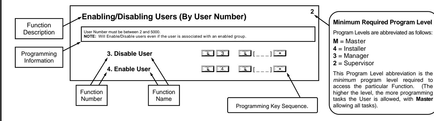
General Program Mode Information
If a wrong key is pressed during code entry, press the key until the error sound is heard (7 short beeps), this will clear the entry. Reenter the key sequence again. All program sequences are followed by the key; 2 short beeps indicate a successful program sequence.
LED and Sounder Indicators
The NETPDK / NETDK keypads provide visual and audible feedback. With a fully charged battery, the feedback is as follows:
| ACTIVITY |
LED
FLASHES |
SOUNDER
BEEP(S) |
COMMENTS |
|---|---|---|---|
| Keypress | 1 RED | 1 | Normal Operation |
| Access Granted or Remote Release | 2 GREEN | 2 | Remote release enabled through activation of relay |
| Invalid Code | 7 RED | 7 | Re-enter User Code |
| Successful Program Entry | 2 GREEN | 2 | When in Program Mode |
| Unsuccessful Program Entry | 7 RED | 7 | When in Program Mode |
| Exit Program Mode |
1 RED, 2
GREEN |
10 | |
| Valid but Disabled Code |
1 GREEN, 4
RED |
1 long, 5 short | Code exists in memory, but disabled |
| Emergency Commands are in effect | 1 RED every two seconds | ||
| NETWORXPANEL Low Battery | Warning displayed in the DL-Windows "Status" screen | ||
| NETDK or NETPDK set to primary | 1 RED | Keypad Identification when two keypads are wired to the NETWORXPANEL | |
| NETDK or NETPDK set to secondary | 2 RED | Keypad Identification when two keypads are wired to the NETWORXPANEL |
Quick Start
The NETDK and NETPDK with proximity card reader are secured single-door or double-door digital keypads for use within the wireless Networx™ system. The NETDK and NETPDK keypads are wired to the dedicated NETWORXPANEL control panel and provide controlled access to a door by releasing a locking device (such as a magnetic lock or electric door strike) when a proper User Code or proximity credential is presented.
The system is capable of controlling two doors using up to two NETDK / NETPDK keypads or two Wiegand devices. In addition, the panel is equipped with two relays that can be independently assigned to either or both keypads. Thus the system can be configured to allow a user to pass in both directions--or in only one direction--through a controlled door.
For more information about installing and configuring a Networx system, see OI383. For NETWORXPANEL installation instructions, including mounting, wiring and initial startup procedures, see WI1856.
Once the NETWORXPANEL, keypad(s) and/or Wiegand devices, locking devices, and other items such as exit buttons and door position contacts are installed, wired and powered, the NETWORXPANEL can be programmed through a NETDK / NETPDK keypad. Note: All programming added using a keypad cannot be retrieved into DL-Windows; thus all programming added via a keypad must be re-added to DL-Windows and downloaded back to the lock(s).
The following are some basic steps to get your system up and running:
Enter Program Mode and Change Factory Master Code
The NETWORXPANEL firmware has only two "modes"--"Normal Mode" and "Program Mode". When you want to make changes to the firmware program, you enter "Program Mode". When you finish programming and wish to put the keypad into use, you exit "Program Mode" to enter "Normal Mode".
- 1. Press the default Master Code: 123456 .
- 2. Wait for the green light and press ; until multiple beeps are heard. You are now in Program Mode.
Note: The NETDK / NETPDK will beep every 6 seconds as a reminder that you are in Program Mode.
3. Enter a new personal 6-digit Master Code number by pressing the following keys:
| ;1; [new Master Code] ; [new Master Code] : (the second set of digits must be exactly the same). | ||
|---|---|---|
(For example, if you want your new Master Code to be "664433". Press: ;1 ;664433 ;664433 : ).
Now that the Master Code has been changed, there is no need to change it again (unless you want to). Since you are still in Program Mode, you can now proceed directly below and program various functions. Note: Programming any Function, such as setting the clock, follows a consistent 5-step pattern: (1) Enter Program Mode (2) Press ; [Function #] (3) Press ; and enter data (4) Press : to end (5) Exit Program Mode.
Note: There is a 3 minute Program Mode timeout if no keys are pressed when in Program Mode. A steady tone will sound for the final 15 seconds of the 3 minute timeout period as a warning. To remain in Program Mode, press any key.
Exit Program Mode
The NETWORXPANEL firmware has only two "modes"--"Normal Mode" and "Program Mode". When you want to make changes to the firmware program, you enter "Program Mode". When you finish programming and wish to put the NETDK and/or NETPDK into use, you exit "Program Mode" to enter "Normal Mode".
To exit Program Mode with a keypad, simply press and hold any key for 3 seconds. Program Mode exit is confirmed by several beeps. If you wish to exit Program Mode using a Wiegand device with its own keypad, press ;8: .
Re-enter Program Mode
If you wish to re-enter Program Mode, key-in your new 6-digit Master Code, and press ; .
Set the Weekday
- 1. Enter Program Mode (if not in already).
- 2. Press ;40; [number of weekday] : . (Use 1= Sunday, 7 = Saturday). (For example - Friday - press ;40 ;6 : ).
Set the Date
- 1. Enter Program Mode (if not in already).
- 2. Press ;38; [MMDDYY] : . (For example - May 10, 2014 - press ;38 ;051014 : ).
Quick Start (cont'd)
Set the Time
- 1. Enter Program Mode (if not in already. If you just finished the above procedure, you are still in Program Mode).
- 2. Press ;39; [HHMM] : . (Use 24-hour military format, where PM adds 12 hours).
(For example - 2:30pm - press ;39 ;1430 : ).
Enter User Codes
User Codes added with Function 2 (described in the following procedure) are enabled for use with any keypad in the system, including Wiegand devices with keypads. For systems with two NETDK / NETPDK keypads ("primary" and "secondary"), to add User Codes for use with only the primary keypad or only the secondary keypad, see Functions 62 and/or 63 on page 21.
- 1. Enter Program Mode (if not in already).
- 2. Press ;2; [User Number] ; [new User Code] : .
(For example, John Smith is designated as User 21. You want him to use the code of "232323" to unlock the door. Program by pressing: ;2 ;21 ;232323 : ).
3. Repeat step 2 for each new user.
Delete a User Code
- 1. Enter Program Mode (if not in already).
- 2. Press ;2; [User Number] : .
The NETDK will beep immediately; the NETPDK will beep for 10 seconds; both will flash a green LED. When the red LED flashes, the User Code is deleted.
3. Repeat step 2 for each new User.
User Code Conflicts
Care should be taken not to program a new User Code which matches the first digits of any other User Code (only the User Code with the least number of digits will be recognized). Example: If User Codes 123 and 123456 are both entered in the system, only code 123 would be recognized, unless the ENTER Key has been enabled (see Function 69, see page 25). In addition, an error will sound if you try to program a new User Code that matches the first digits of the Master Code.
WARNING: When attempting to change an existing Master Code, it is HIGHLY recommended that you enable all Groups (see Function 23 on page 16), exit Program Mode, and enter the new anticipated Master Code to verify that the anticipated sequence does not currently open the protected door. If the protected door does not open, the anticipated Master Code can be used as the new Master Code; if the protected door opens, the anticipated Master Code already exists in the system (as a User Code), and the anticipated Mater Code should NOT be used. Always repeat this procedure with any new anticipated Master Codes.
Enroll Proximity Cards (Single Enrolling or Batch Enrolling)
If you wish to enroll only one proximity card (" Single Enrolling ") or many (" Batch Enrolling "), the process is basically the same. Only the NETPDK has an integral proximity reader, therefore the NETPDK will be used in the following steps:
- 1. Enter Program Mode (if not in already).
- 2. Press ;2; [User Number] : . (Enter the User Number you wish to match with the first proximity card).
- 3. The NETPDK will beep continuously. Place a new proximity card in front of the reader (under the keypad). When the NETPDK beeps three times, the card has been enrolled.
- 4. Press ; to end the process. To return to normal operation, exit Program Mode (see page 10).
(For example, you wish to enroll two proximity cards for User 14 and User 15 respectively. Press ;2 ;1 4: . and place the first card in front of the reader (hear 3 beeps) and then within 10 seconds, place the second card in front of the reader (hear 3 beeps)).
You can continue entering cards in this way, automatically incrementing the User number with each presentation of a proximity card. When finished, press ; .
Note: Batch Enrolling will not program Users 297 through 300, as these are Special Function User Codes (see page 7). After a proximity card for User 296 has been Batch Enrolled, the next card presented will enroll as User 301.
High Security Access (ProxCard & User Code Access)
Program the NETPDK for High Security Access for User Number 15 , with a proximity card and a User Code of 7452 required for access. Only the NETPDK has an integral proximity reader, therefore the NETPDK will be used in the following steps:
1. Enter Program Mode (if not in already).
- 2. Press ;2 ;15 : .
- 3. The NETPDK will beep continuously. Place a new proximity card in front of the reader (under the keypad). When the NETPDK beeps three times, the card has been enrolled.
- 4. Press ;2 ;15 ;7452: .
In order for User 15 to open the NETPDK, a User Code must be entered and a proximity card must be presented to the NETPDK. The User may enter code or present card in either order to open the NETPDK. The sounder will beep for up to 10 seconds, waiting for the User to enter their User Code and present their card. Note: If two keypads are used in one system (wired to one NETWORXPANEL control panel), the programming of "High Security Access" is supported ONLY if both keypads installed are NETPDK model keypads. In addition, "High Security Access" may not be used with Wiegand devices unless both are equipped with combination keypad and proximity reader. See the NETWORXPANEL installation instructions (WI1856) for supported Wiegand devices.
Delete a High Security Access Code
Note: Deleting a proximity card associated with a User Number will also delete the User Code programmed for that User Number. Delete the proximity card by not presenting any card for enrollment, as follows:
- 1. Enter Program Mode (if not in already).
- 2. Press ;2; [User Number] : . (Enter the User Number matched to the proximity card you want to delete).
- 3. The NETPDK will beep continuously. Do not present ANY card during this step. Wait until NETPDK stops beeping, about 10 seconds.
- 4. Press ; to end.
You are now ready to distribute User Codes. Before installation, it is suggested you test and verify that all User Codes entered are active (see below).
Testing the Codes Entered
Verifying Basic Keypad User Codes
Test a User Code. Press the User Code at the keypad.
VALID CODE: The Green LED will flash momentarily and the sounder will beep a few times after a valid code is entered.
INVALID CODE: The RED LED will flash several times and the sounder will beep several times after an invalid code is entered. Use Function 2 to re-program the code.
Verifying Proximity Card and Keyfob Access
Test a programmed proximity card or keyfob. Present the programmed proximity card (or keyfob ) to the proximity reader in front of the NETPDK.
VALID CARD: The Green LED will flash momentarily and the sounder will beep a few times after a valid card or keyfob has been presented to the NETPDK.
INVALID CARD: The RED LED will flash several times and the sounder will beep several times after an invalid valid card or keyfob has been presented to the NETPDK. Use Function 2 to re-program the code.
Verifying High Security Access (Proximity Card and User Code)
Test proximity card programmed for High Security Access. The proximity card (or keyfob) and a User Code are both required for access.
- 1. Press the User Code for the User Number programmed for High Security Access. The sounder will beep slowly for up to 10 seconds.
- 2. Present the proximity card programmed for the same User Number.
User may enter User Code or present the proximity card in either order. The sounder will beep for up to 10 seconds, waiting for the User to enter User Code or to present the proximity card / keyfob. Note: Do not present the proximity card / keyfob and enter the User Code simultaneously.
Programming Functions--Overview
| Function 1 | Change Master Code | See page 14 |
|---|---|---|
| Function 2 | Add/Delete/Change User Codes | See page 14 |
| Function 3 | User Disable (By User Number) | See page 15 |
| Function 4 | User Enable (By User Number) | See page 15 |
| Function 5 | User Enable with Timeout | See page 15 |
| Function 6 | Enable Total User Lockout | See page 15 |
| Function 7 | Disable Total User Lockout | See page 15 |
| Function 8 | Exit Program Mode | See page 15 |
| Function 9 | Enable User 300 (Service Code) | See page 15 |
| Function 10 |
Erase All Users Except the Mas
ter Code |
See page 15 |
| Function 11 | Reserved | |
| Function 12 |
Clear All Schedules and Timeout
Functions |
See page 16 |
| Function 13 | Clear All Timeout Functions | See page 16 |
| Function 14 - 17 | Group 1-4 Disable | See page 16 |
| Function 18 | Disable All Groups | See page 16 |
| Function 19 - 22 | Group 1-4 Enable | See page 16 |
| Function 23 | Enable All Groups | See page 16 |
| Function 24 | Reserved | |
| Function 25 - 28 | Group Disable with Timeout | See page 17 |
| Function 29 | Disable All Groups with Timeout | See page 17 |
| Function 30 - 33 | Group Enable with Timeout | See page 17 |
| Function 34 | Disable All Groups with Timeout | See page 17 |
| Function 35 | Group Add/Delete Association | See page 17 |
| Function 36 - 37 | Reserved | |
| Function 38 | Set Date | See page 18 |
| Function 39 | Set Time | See page 18 |
| Function 40 | Set Weekday | See page 18 |
| Function 41 | Daylight Saving Time Start Date | See page 18 |
| Function 42 | Daylight Saving Time End Date | See page 18 |
| Function 43 | Speed Up Clock | See page 19 |
| Function 44 | Slow Down Clock | See page 19 |
| Function 45 - 46 | Passage Mode Enable/Disable | See page 19 |
| Function 47 | Timed Passage Mode | See page 19 |
|
Function 48
Enable Passage Mode See page 20 Function 49 Disable Passage Mode See page 20 Return to Normal Passage Mode Function 50 See page 20 Schedule Function 51 Passage Mode Configuration See page 20 Function 52 - 54 Pass Time See page 20 Function 55 Reserved Function 56 Reserved Function 57 Reserved Function 58 Reserved Function 59 Reserved Number of Attempt Before Key Function 60 See page 21 pad Lockout Set the Attempts Keypad Lockout Function 61 See page 21 Time Add/Delete/Change User Codes 2 Function 62 -5000 (for Primary Keypad Code See page 21 Entry) Add/Delete/Change User Codes 2 Function 63 -5000 (for Secondary Keypad See page 21 Code Entry) Function 64 - 65 Disable/Enable Remote Input See page 21 Function 66 Ambush Code See page 21 Function 67 Add Relay/System Features See pages 22-24 Delete All Relay Functions and System Options added by Func Function 68 See page 25 tion 67 Door Ajar Time Function 69 - 70 Enable/Disable Enter Key See page 25 Function 71 Reserved Scheduled Enable/Disable Function 72 - 73 See page 25 Passage Mode Function 74 - 77 Schedule Enable Group 1 - 4 See page 25 Function 78 Schedule Enable All Groups See page 25 Function 79 - 82 Schedule Disable Group 1 - 4 See page 25 Function 83 Schedule Disable All Groups See page 25 Function 84 - 87 Quick Schedules - Enable Group See page 26 Passage Mode Function 88 See page 26 (Open Time Window) Passage Mode Function 89 See page 26 (Close Time Window) Relay Activation Function 90 See page 27 (Open Time Window) Relay Activation Function 91 See page 27 (Close Time Window) Enable Group 4 Function 92 See page 28 (Open Time Window) Enable Group 4 Function 93 See page 28 (Close Time Window) Function 94 Disable Radio See page 28 Function 95 - 98 Reserved Function 99 Clear All Lock Programming See page 28 |
||
|---|---|---|
Programming Functions
USERS
|
1. New Master Code
(User Number 1) |
; 1 | ;[ ] | (New Master Code) |
; [ ] :
(Confirm New Master Code) |
|---|---|---|---|---|
|
Master Code must be 6 digits-only. Master Code is Keypad Code Access only. Factory Default = 123456 See "General Overview" on page 5 for more information about Master Codes. |
M | |||
|
2. Adding and Deleting User Codes and/or Proximity
Cards (for User Numbers 2-5000) |
||||
| (Entering a "User Code" / "PIN No. Code" into the lock programming) | ; 2 ;[ ] ; [ ] : | |||
|
User Codes added with Function 2 are enabled for
use with ALL keypads in the system, including Wiegand devices with keypads. "Two-Door Mode": For systems with two |
(Entering a Proximity
Card) |
(User Number)
(User Number) |
(User Code)
; 2 ;[ ] :[Beep Beep Beep] (Present card to reader |
|
|
NETPDK keypads ("primary" and "secondary"), to
add User Codes for use with only the primary key pad or only the secondary keypad, see Functions 62 and/or 63. Using Function 2 with Two-Door Mode will add the User Code to both keypads. |
(User Number) |
within 10 seconds)
(Deleting Entire User) ; 2 ;[ ] :[Beep Beep Beep] (If NETPDK, wait 10 |
||
|
User Number must be between 2 and 5000.
User Code must be 3-6 digits. Each User Code can be thought of as a person. As long as each person possesses their own unique User Code, you can control access by adding or deleting User Codes. See "Terminology Used in this Manual" on page 6 for more information. |
3 |
seconds for beeping
to end) |
Programming Level Defaults for the NETWORXPANEL
Users added will default to a Group Association and a Programming Level ability as follows:
| USER TYPE | USER NUMBER |
GROUP DEFAULT
ASSOCIATION |
MINIMUM PROGRAM
LEVEL (See page 6) |
|---|---|---|---|
| Master Code | 1 | - | M |
| Installer Codes | 2 & 3 | none | 4 |
| Manager Codes | 4 - 6 | none | 3 |
| Supervisor Codes | 7 - 9 | none | 2 |
| (Reserved) | 10 - 11 | none | |
| Basic User Codes | 12 - 50 | none | none |
| Basic User Codes Group 1 | 51 - 100 | 1 | none |
| Basic User Codes Group 2 | 101 - 150 | 2 | none |
| Basic User Codes Group 3 | 151 - 200 | 3 | none |
| Basic User Codes Group 4 | 201 - 250 | 4 | none |
| Basic User Codes | 251 - 296 | none | none |
| Quick Enable User 300 Code | 297 | none | none |
| (Reservedsee page 7) | 298 | none | none |
| Guard Tour Code* | 299 | none | none |
| Service Code | 300 | none | none |
| Basic User Codes | 301-5000 | none | none |
* This code is a Non-Pass code and therefore does not allow passage through the door.
USERS (Continued)
| NOTE: Use Function 3 to disable a specific User Number and their associated User Code. Will Enable/Disable Users even if |
the User is associated with an enabled Group. If the disabled User Code is entered, the NETPDK will flash 1 green and 4 red flashes
(with 1 long and 5 short beeps) indicating that the User Code exists in memory, but is disabled. Function 4 will "undo" Function 3. |
||
|---|---|---|---|
| 3. Disable User | ; 3 |
; [ ]:
(User Number) |
|
| 4. Enable User | ; 4 |
; [ ]:
(User Number) |
|
|
5. User Enable with Timeout
(Enter Timeout, XXX Hours) (This Function enabled through keypad only) |
; [ ]
; [ ] : ; 5 (User Number) (XXX Hours) |
||
|
With Function 5, User Numbers must be between 2-5000, hours must be between 001-999. Function 5 can temporarily override a disabled User (disabled using Function 3 above). |
2 | ||
|
Since this is a temporary setting, Function 5 can only be enabled using the keypad. |
Example: Brian, User Number 1157, rarely works at the office, but when he does, enable him for his 8 hour work day
by entering Program Mode and pressing: ;5 ;1157 ;008:. |
||
| gram more than 4 Timeout Functions. | NOTE: Up to 4 Timeout Functions may be pending at any one time. An error beep will sound when attempting to pro | ||
| User Lockout Mode | |||
|
Function 6 is programmed, the NETWORXPANEL will remain in Passage Mode.
6. Enable Total User Lockout Mode |
Disables all User Codes (Except the User Number 1 Master Code). Note: No other programming functions or schedules
(including a DL-Windows data transfer) will re-enable User Codes. User Codes must be re-enabled with Function 7. Note: Does not change the User enable/disable status. Note: If the NETWORXPANEL is currently in Passage Mode ("door unlocked") and ; 6 : |
M | |
|
(This Function enabled through keypad only)
7. Disable Total User Lockout Mode (This Function enabled through keypad only) |
; 7 : | ||
| 8. Exit Program Mode | ; 8 : | ||
| Allows Program Mode exit for keypads without hold-down functionality, such as some Wiegand readers with integral keypads. | 3 | ||
|
9. Enable User 300
(Service Code) |
; 9 : | ||
| 2 | |||
|
Service Code is a One-Time-Only Code. Once it is used, it is disabled until enabled again.
for more information and examples regarding special Users 297-300. |
NOTE: User Number 297 is used to reset Service Code Use. See "Terminology Used in this Manual" on page 7 | ||
|
10. Erase All Users Except the Master Code
(This Function enabled through keypad only) |
(User 1)
; 1 0 ; 0 0 0 : |
CLEAR FUNCTIONS
12. Clear All Schedules and Timeout Functions ; 1 2 ; 0 0 0 :
Function 12 clears all programmed Schedules and all Timeout Functions . (To clear All Timeout Functions only, see Function 13 below). Function 12 will clear all of the following: All Schedule Functions 72 through 93, Timeout Functions 5, 25 through 34 and Function 47. Note: Function 12 also resets Passage Mode and any disabled Groups. After using Function 12, your Scheduled/Timeout Functions must be manually re-programmed.
NOTE: Up to 4 Timeout Functions may be pending at any one time. An error beep will sound when attempting to program more than 4 Timeout Functions. This Function only disables the timeout; the event associated with the timeout will remain.
3
13. Clear All Timeout Functions
; 1 3 ; 0 0 0 :
(This Function enabled through keypad only)
Function 13 clears all Timeout Functions . (To clear All Schedules and Timeout Functions, see Function 12 above). Function 13 will clear all of the following: All Timeout Functions 5, 25-34 and Function 47. After using Function 12, your Scheduled/Timeout Functions must be manually re-programmed.
3
NOTE: Up to 4 Timeout Functions may be pending at any one time. An error beep will sound when attempting to program more than 4 Timeout Functions. This Function only disables the timeout; the event associated with the timeout will remain.
Important: It is the responsibility of the programmer to verify the proper lock/unlock conditions and Group conditions after programming Function 12 and 13.
GROUPS
Group Enable/Disable
Enter the functions below to Enable/Disable Groups. Functions 14 - 23 will each override existing scheduled events. Therefore, Functions 14 - 23 are temporary, take effect immediately, and are always overridden by future scheduled events that already exist within the lock programming.
2
- 14. Disable Group 1
- ; 1 4 :
- 15. Disable Group 2
- ; 1 5 :
-
16.
Disable Group 3 ; 1 6 :
- 17. Disable Group 4 ; 1 7 :
-
18.
Disable All Groups ; 1 8 :
- 19. Enable Group 1 ; 1 9 :
- 20. Enable Group 2 ; 2 0 :
- 21. Enable Group 3 ; 2 1 :
- 22. Enable Group 4 ; 2 2 :
- 23. Enable All Groups ; 2 3 :
PRIORITY ORDER
- 1. Disabled Users
- 2. Enabled Groups
- 3. Disabled Groups
- 4. Enabled Users
The Priority Order details which Function will take effect before ("have priority over") others. As per the list above, Enabled Users have the lowest priority, and other Functions can affect the status of these Users. Disabling a Group (Functions 14-18) will take priority over the enabled Users in that Group, disabling them. Enabling Groups (Functions 19-23) will take priority over those tasks lower in the list, and finally disabling a User (Function 3) takes priority over all other tasks listed.
24. Reserved
GROUPS
NOTE: Clear All Timeout Functions by entering Function 13.
Group Enable/Disable with Timeout (Enter Timeout, XXX Hours)
(Functions 25-34 are enabled through the keypad only)
|
within the lock programming. NOTE: Functions 25-34 are enabled through the keypad only. |
Hours must be between 001-999. Enter the functions below to Enable/Disable Groups for the amount of time entered in
hours. NOTE: Only 4 Timeout Functions are allowed at any one time. An error beep will sound when attempting to program more than 4 Timeout Functions. Functions 25 - 34 will each override existing scheduled events. Therefore, Functions 25 - 34 are temporary, take effect immediately, and are always overridden by future scheduled events that already exist |
|
|---|---|---|
| |
Example: All 15 members of the Accounting Department are members of Group 4, and a schedule programmed
in the department's NETWORXPANEL reflects their normal working hours of 9 AM through 5 PM, Monday through Fri day. But one day a special event occurs, and all Accounting Department members are requested to stay an extra hour until 6 PM. Therefore, at 5 PM, the manager (wishing to temporarily enable Group 4 users for an extra hour) enters Program Mode and presses: ;33 ;001:. Likewise, if the manager wished to send his department home early at 3 PM, the manager could enter ;28 ;002:. |
|
| 25. Timed Disable Group 1 | ; 2 5 |
; [ ] :
(XXX Hours) |
| 26. Timed Disable Group 2 | ; 2 6 |
; [ ] :
(XXX Hours) |
| 27. Timed Disable Group 3 | ; 2 7 |
; [ ] :
(XXX Hours) |
| 28. Timed Disable Group 4 | ; 2 8 |
; [ ] :
(XXX Hours) |
| 29. Timed Disable All Groups | ; 2 9 |
; [ ] :
(XXX Hours) |
| 30. Timed Enable Group 1 | ; 3 0 |
; [ ] :
(XXX Hours) |
| 31. Timed Enable Group 2 | ; 3 1 |
; [ ] :
(XXX Hours) |
| 32. Timed Enable Group 3 | ; 3 2 |
; [ ] :
(XXX Hours) |
| 33. Timed Enable Group 4 | ; 3 3 |
; [ ] :
(XXX Hours) |
| 34. Timed Enable All Groups | ; 3 4 |
; [ ] :
(XXX Hours) |
| 35. Group Add/Delete Association | ; 3 5 |
; [ ]
; [ ]: (User Number) (Groups) |
ates) a selected User with a selected Group (Groups not selected are then disassociated from the User). Function 35 is helpful when the number of Users you wish to add to a Group outgrows the number of User Numbers defaulted to a Group (50); or if an existing User joins a department and you wish to simply add them to a Group.
User Number must be between 2 and 5000; Groups 1-4 (to associate with User) may be selected.
Add Example : To associate User 67 with Groups 1, 2 and 4;
Enter: ; 3 5 ; 6 7 ; 1 2 4 :
Delete Example : To remove all Group associations for User 67;
Enter: ; 3 5 ; 6 7 :
NOTE: If a User is associated with more than one Group, all associated Groups would have to be disabled before the User is disabled.
36 - 37. Reserved
CLOCK SETTINGS
| 38. Set Date | ; 3 8 |
;[ ] :
(Date) |
|
|---|---|---|---|
|
Use Month Day Year format - MMDDYY - Single digit months and days are entered with a preceding zero.
Enter ONLY the last two digits of the year. |
3 | ||
|
For Example: March 8, 2002; Enter:
; 3 8 ; 0 3 0 8 |
0 2 : | ||
| 39. Set Time | ; 3 9 |
; [ ] :
(Time) |
|
|
Time must be 4 digits
Use 24-Hour Format (add 12 hours to program PM time) |
3 | ||
|
For Example: To set time to 8:25PM;
Enter: ; 3 9 ; 2 0 2 5 : |
|||
|
For Example: To set time to 8:25AM;
Enter: ; 3 9 ; 0 8 2 5 : |
|||
| 40. Set Weekday | ; 4 0 |
; [ _ ] :
(Day) |
|
|
For day enter: 1 for Sunday, 2 for Monday, 3 for Tuesday, 4 for Wednesday, 5 for Thursday, 6 for Friday and 7 for Saturday. For Example: To set day to Sunday; Enter: ; 4 0 ; 1 : |
3 | ||
| 41. Daylight Saving Time Start Date |
;41;[ M M W D ] :
(DST Starting Month, Month, Week, Day) |
||
|
The manner in which Daylight Saving Time (DST) is observed varies with location, therefore the DST adjustment is fully flexible to
accommodate these regional differences. Function 41 allows the entry of a DST Start Date (month, day and week), and Function 42 allows the entry of a DST End Date (month, day and week). DST begins and ends at 2AM on the programmed date. En |
4 | ||
|
ter ;41;000:to disable DST. All locks leave the factory with DST enabled and pre
programmed to the following start and end dates (for the USA beginning 2007): |
|||
|
Default DST Start Date: March, Week 2, Sunday ("Second Sunday in March") |
|||
|
Default DST End Date: November, Week 1, Sunday ("First Sunday in November") |
|||
|
To program the DST start date using the keypad, press: ;41;[ M M W D ] : where "M M W D" repre
sents: |
|||
|
"M M" = Two digits of the month (01 through 12 = January through December. Single digit months are entered with a preceding zero). |
|||
|
"W" = Single digit for "week of the month" (valid entries are 1-5 where "1" is the first week, "2" is the second week, "3" is the third week, "4" is the fourth week and "5" is the last week of the month. |
|||
|
"D" = Day of the week (valid entries are 1-7: 1 for Sunday, 2 for Monday, 3 for Tuesday, 4 for Wednesday, 5 for Thursday, 6 for Friday and 7 for Saturday). |
|||
| Example: To set the default start date of "second Sunday in March", press: | |||
| ;41;[ 0 3 2 1 ] : (03 = "March", 2 = "2nd week", 1 = Sunday). | |||
| 42. Daylight Saving Time End Date |
;42;[ M M W D ] :
(DST Ending Month, Month, Week, Day) |
CLOCK ADJUST
Clock Adjust
|
Number of seconds to adjust (speed up/slow down) the clock each day must be between
0-55 seconds. |
4 | |||
|---|---|---|---|---|
|
Note: Repeated use of these Functions are not "cumulative" (this means, for ex
ample, if the clock has already been set to speed up 10 seconds per day, and then is found to need an additional 10 seconds, then program 20 seconds using Function 43). |
Clock Accuracy |
The internal oscillator is factory calibrated to an
accuracy of ±5 minutes/year. Changes in ambi |
||
|
Example 1: Clock is losing 13 seconds every day, enter:
; 1 3 :. ; 4 3 |
ent temperature may affect accuracy. If neces
sary, the accuracy of the internal clock may be adjusted by first updating the correct time via Func |
|||
| This example assumes that the Clock Adjust setting was at the factory default of zero. |
tion 39. After an interval of about 1 month, re-set the
correct time via Function 39 and then view the Audit |
|||
|
Example 2: Clock is gaining 13 seconds every day, enter:
; 1 3 :. ; 4 4 |
Log. Because the Audit Log displays both the "New
Clock Time" and the "Old Clock Time", a daily accu racy (in seconds) can be determined by taking the |
|||
| This example assumes that the Clock Adjust setting was at the factory default of zero. |
difference in seconds between the "Old" and "New"
times divided by the number of days between the |
|||
|
Example 3: To set the clock adjust setting back to the factory default of zero, en
ter: ; 4 3 : or ; 4 4 : |
two Function 39 entries. Note: Because the mini
mum available adjustment is 1 second per day, the inaccuracy of the clock must exceed about 6 minutes |
|||
| per year before adjustment is necessary. | ||||
|
43. Speed Up Clock
(This Function enabled through keypad only) |
; 4 3 |
; [ ]:
(seconds) |
||
| 44. Slow Down Clock | ; 4 4 | ; [ ]: | ||
| (This Function enabled through keypad only) | (seconds) | |||
| PASSAGE MODE | ||||
| Passage Mode Enable/Disable - Schedule will Override | ||||
| 2 | ||||
|
Function 45 allows passage through the door without the need for a User Code. Disable Passage Mode with Function 46.
Programmed Schedules will override the state of the NETWORXPANEL when Functions 45 and 46 are used. If it is re |
||||
|
quired that programmed schedules do not override Passage Mode, enable/disable Passage Mode using Functions 48/49.
Note: Because of the temporary nature of these settings, Functions 45-47 can only be enabled using the keypad. |
||||
| Note: With Functions 45-49, if "Two-Door Mode" is enabled, see page 24 "Advanced Two-Door Mode Setup". | ||||
|
45. Enable Passage Mode
(This Function enabled through keypad only) |
; 4 5 : | |||
|
46. Disable Passage Mode
(This Function enabled through keypad only) |
; 4 6 : | |||
|
47. Timed Passage Mode
(This Function enabled through keypad only) |
; 4 7 |
; [ ] :
(XXX Hours) |
||
|
Hours must be between 1 - 999. Function 47 allows passage through the door without the need for a User Code for the programmed amount of time. |
2 | |||
|
For example, if you wish your NETWORXPANEL to "unlock" the secured door ("unlocked" = "Passage Mode") for the next 3 hours, enter Program Mode and press: ;47;003: |
PERMANENT PASSAGE MODE
Passage Mode Enable/Disable - Schedule will not Override
- Function 48 allows passage through the door without the need for a User Code. Disable Passage Mode with Function 49.
- Programmed Schedules will not override the state of the system using functions 48 and 49. If it is required that programmed schedules override Passage Mode, Enable/Disable Passage Mode using Functions 45/46. Use Function 50 to "undo" Functions 48 and/or 49, and therefore return the NETWORXPANEL to all pre-existing scheduled functions. Note: Functions 48-50 can only be enabled using the keypad. Warning: Function 49 will inhibit all scheduled Passage Mode events.
| 48. Enable Permanent Passage Mode |
|---|
(This Function enabled through keypad only)
49. Disable Permanent Passage Mode
(This Function enabled through keypad only)
50. Return to Normal Passage Mode Schedule
(This Function enabled through keypad only)
(The NETWORXPANEL will enable or disable Passage Mode depending on the current schedule). Use Function 50 to "undo" Functions 48 and/or 49, and therefore return the NETWORXPANEL to all pre-existing scheduled functions.
NOTE: See Scheduled functions 72 and 73 for Scheduled Passage Mode.
51. Passage Mode Configuration ; 5 1 ; [ _ ] :
(Mode)
; 4 9:
; 5 0 :
4
; 4 8 :
- Mode 1 (Normal): Passage Mode must be enabled/disabled using Function 45 and 46. Mode 1 (Normal) is the factory default.
- Mode 2: Group 2 toggles Passage Mode. Each time any member of Group 2 enters their User Code, they will toggle Passage Mode. For example, if Passage Mode is enabled, and a Group 2 User enters their User Code, Passage Mode will be disabled. If a few seconds later they enter their User Code again, Passage Mode will be enabled. Note: If "Two-Door Mode" is enabled, see page 24 " Advanced Two-Door Mode Setup ".
- Mode 3: Group 2 enables, Group 3 disables Passage Mode. Disable Passage Mode has priority if User is a member of both Groups 2 and 3. Group 2 members will always enable Passage Mode, and Group 3 members will always disable Passage Mode. For example, if Passage Mode is already enabled, and a Group 2 User enters their User Code, the Passage Mode status will not be changed. If Passage Mode is already enabled, and a Group 3 User enters their User Code, Passage Mode will become disabled. Note: If "Two-Door Mode" is enabled, see page 24 " Advanced Two-Door Mode Setup ".
PASS TIME
52. Set Pass Time to 3 Sec. ; 5 2 :
; 5 3 : 53. Set Pass Time to 10 Sec.
; 5 4 : 54. Set Pass Time to 15 Sec.
The Pass Time is the length of time the secured door stays "unlocked" after a valid User Code is entered. When the Pass Time expires, the NETWORXPANEL will cause the secured door to "re-lock" automatically. Use the functions below to change the Pass Time to 3, 10 or 15 seconds. The Pass Time is defaulted to 3 seconds.
55 - 59. Reserved
20
2
4
KEYPAD LOCKOUT
| 60. Number of Attempts Before Keypad Lockout |
; [ _ ] :
; 6 0 (Number of Attempts) |
|---|---|
|
Number of attempts before the keypad is locked-out must be 1-9 attempts.
The attempt count is reset each time a valid code is entered. |
4
The number of attempts is reduced by half every time the keypad is locked-out without a successful code entry (default is 6 attempts). Note: In Two-Door Mode, "Keypad Lockout" only applies to the individual keypad responsible. See WI1856 for more information. |
| 61. Set the Attempts Keypad Lockout Time |
; [ ] :
; 6 1 (Keypad Lockout Time) |
|
Keypad Lockout Time must be 1-60 seconds.
Program the length of time the keypad is locked-out after a series of unsuccessful attempts (default is 18 seconds). |
4
Note: In Two-Door Mode, "Keypad Lockout" only applies to the individual keypad responsible. See WI1856 for more information. |
|
62. Add/Delete/Change User Codes 2-5000
(for Primary Keypad Code Entry) |
;62 ;[ ]
; [ ] : (User Number) (User Code) |
|
exit Programming Mode. If more programming is desired, re-enter Programming Mode.
User Code must be 3-6 digits. |
3
User Number must be between 2 and 5000. User Codes entered are enabled for use with the Primary keypad only. To delete a code, leave the User Code blank and wait for the rapid beeping to stop, then press and hold : for three seconds to Each User Code can be thought of as a person. As long as each person possesses their own unique User Code, you can control access to the lock by adding or deleting User Codes. See "Terminology Used in this Manual" on page 6 for more information. |
|
(for Secondary Keypad Code Entry)
Same as Function 62, except User Codes entered are enabled for use with the Secondary keypad only. |
;63 ;[ ]
; [ ] : (User Number) (User Code) 3 |
| REMOTE INPUT |
Wire a Normally Open Contact to NETWORXPANEL terminals T26 & T27. Momentarily close switch to unlock door to allow
2 |
|
; 6 4 :
; 6 5 : |
passage. Enter the functions below to Disable/Enable the Remote Input. NOTE: The Remote Input is enabled by default.
Note: In addition to using a wired momentary switch, Function 65 is also used to pair a compatible Wireless Remote Release such as the RR-1BUTTON (see WI1999) or the portable pocket-size RR-4BKEYFOB (see WI2004). Func tion 64 is also used to remove all paired Wireless Remote Releases from the locking device. Be aware of the potential loss of Wireless Remote Release pairing(s) that can result from using Function 64. Refer to the above WIs for complete instructions. |
|
63. Add/Delete/Change User Codes 2-5000
Remote Input 64. Disable Remote Input 65. Enable Remote Input AMBUSH 66. Ambush Code |
;[ ]:
; 6 6 |
Function 67 Features
67. Add Feature
| ;67 | ;[ ]: |
|---|---|
| (Feature Number) |
Auxiliary Relay Features (14-23 Reserved)
Use Function 67 to program one or more feature(s) and the Auxiliary Relay (NETWORXPANEL terminals T16-T18 shown below) will energize for two seconds (unless otherwise specified) when the programmed feature(s) listed below occurs. Note: For information about the Remote Input , see page 21 (Function 65). Delete all system features with Function 68.
- 1. Remote Input switch closed and Function 65 Remote Input enabled. Because the Remote Input is enabled by factory default, the Aux Relay will energize when the Remote Input switch is closed.
- 2. Remote Input switch closed and Function 64 Remote Input disabled. If the Remote Input is disabled with Function 64, the Aux Relay will energize when the Remote Input Switch is closed.
- 3. Failed attempted entry. Aux Relay energizes for 2 seconds when an attempted User Code entry (or proximity card / keyfob) fails.
- 4. Disabled User or Group. Aux Relay energizes for 2 seconds when a disabled User or disabled Group member enters a User Code (or proximity card / keyfob).
- 5. Follow Access Granted. When a valid User Code is entered into the keypad and the secured door "unlocks", the Aux Relay energizes for 2 seconds. Compare with Event 31.
- 6. Scheduled Group 1 User Code. Aux Relay energizes for 2 seconds when a scheduled Group 1 User Code (or proximity card / keyfob) is entered. See Function 90, page 27.
- 7. Scheduled Lock Event. Aux Relay energizes for 2 seconds when the NETWORXPANEL "locks" the secured door by a Schedule.
- 8. Scheduled Unlock Event. Aux Relay energizes for 2 seconds when the NETWORXPANEL "unlocks" the secured door by a Schedule.
- 9. Keypad Lockout. Aux Relay energizes for 2 seconds when a Keypad Lockout occurs (i.e. number of attempts is exceeded, see Function 60).
- 10. Ambush. Aux Relay energizes for 2 seconds when Ambush is tripped. See Function 66, page 21.
- 11. First Key Press or Proximity Credential. Aux Relay energizes for 2 seconds at the first key press of any sequence or upon the presentation of ANY (enrolled or un-enrolled, enabled or disabled) proximity card / keyfob.
- 12. Relay On Door Ajar. If the door is held open for longer then the allowed Door Ajar Time (programmed at function 68) the Aux Relay will engage for 2 seconds. See "Door Ajar" in glossary.
- 13. Create "Two-Door Mode". If set, all existing Aux Relay features are erased, and a two-door system is created: The primary DK keypad addressed as Keypad 1 for Door 1 (or Wiegand device wired to NETWORXPANEL terminal "W0") will activate the NETWORXPANEL Main Relay. The secondary Alarm Lock keypad addressed as Keypad 2 for Door 2 (or Wiegand device wired to terminal "W0A") will activate the Aux Relay. Note: With Two-Door Mode enabled, the programming of any other relay feature will disable Two-Door Mode. See " Advanced Two-Door Mode Setup " (features 51-55) on page 24.
Ambush Function
- 1. Connect relay to a device able to properly monitor dry contacts for an Ambush condition.
- 2. Program the Relay for Ambush Tripped using Program Function 67, feature 10 above.
- 3. Set the Ambush Code using Program Function 66.
- 4. When the Ambush Code is entered followed by a valid User Code (or proximity card), the relay will close for 2 seconds.
Notes: The Ambush Code defaults to 99 . An error will sound if you try to program a new User Code starting with the Ambush Code.
- * Features 26, 27 & 28 will delay User Codes 12 and higher only (except 297, 298 and 299, and any Emergency Command enabled User).
- ** Features 30, 31 & 32: Note: Scheduled events and Door Ajar monitoring (and their associated audit trail entries) will not occur during sustained closure of the remote input. NOTE: Enter ;67;000: to delete all Relay Features added by Function 67 (identical to Function 68).
- *** Feature 24, "One Time Access for Group 3 Users", allows the creation of multiple 'one time only' User Codes. When activated, an entry by a Group 3 User allows entry only once, then user becomes disabled. Note: When the User Code is entered for the first time and access is granted, the Event Log will read "Entry" followed by "User Disabled". If the User Code is entered a second time, access will be denied, and the Event Log will read "User Denied Access".
To Enable the Feature: Enter Program Mode and enter the key sequence ;67;24: .
To assign the selected User Codes to Group 3: For example, to assign User Number 15 to Group 3, press: ;35;1 5;3: .
- † Emergency Commands are disabled until a download from DL-Windows is performed. If a Function 67 or 68 (Clear Relay) is performed, Emergency Commands are turned off.
- † † Upon initial power up of the lock, options 39, 45 and 47 are enabled. A subsequent profile download from DL-Windows will enable 38, 39, and 45 through 48.
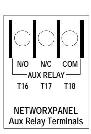
4
Function 67 Features (cont'd)
- 14. Activate Relay on Forced Door. Relay activates when door is forced ("door open") without prior valid credential entry. Note: Enable Door Ajar Monitor On (feature 40) and Forced Door Detection (feature 42) must first be enabled.
- 15. Activate Relay on Emergency. Relay activates for all emergency commands.
- 31. Follow Access Granted--No Time Limit.** When a valid User Code is entered and the secured door unlocks, the Aux Relay energizes for the same amount of time as the programmed Pass Time . (The Pass Time is the length of time the secured door stays "unlocked" after a valid User Code is entered; see Functions 52-54). Use this feature for remote monitoring or other activation as this feature works independently of all other Aux Relay options. Enabling this feature supersedes all other programmed Aux Relay features. Subsequent Aux Relay feature programming will not take effect while this feature is active. Before enabling any other Aux Relay features, press ;68;000: to delete this feature.
System Options
- 24. One Time Access for Group 3 Users***
- 25. Disable Sounder
- 26. Five (5) second Delayed Entry *
- 27. Fifteen (15) second Delayed Entry *
- 28. Forty-five (45) second Delayed Entry *
Remote Input Functions
- 29. Toggle Passage Mode. Remote Input toggles Passage Mode. If "Two-Door Mode" is enabled, see page 24 " Advanced Two-Door Mode Setup ".
- 30. Forced Unlock Follows Remote Input. ** When Remote Input switch is closed, regardless of the current state of the system, the system "unlocks" for the duration of the Remote Input switch closure. If "Two-Door Mode" is enabled or if features 51-55 are enabled, both doors will be triggered.
- 32. Remote Input Disables Unit. ** Regardless of the current state of the system, that state will remain unchanged, and keypad (s) will be disabled (including its proximity reader, if present) for the duration of Remote Input switch closure.
- 34. Forced Lock Follows Remote Input. ** When Remote Input switch is closed, regardless of the state of the system, the system will "lock" for the duration of the Remote Input switch closure. If "Two-Door Mode" is enabled or if features 51-55 are enabled, both doors will be triggered.
Enable Emergency Commands
- 38. Emergency Commands Enable (default = ON)
- 39. User Lockout on Emergency (default = ON)
Door Ajar
- 40. Door Ajar Monitor On (default = OFF). If this feature is set ("ON") and the Door Position Contacts remain open past the time set at Function 68 "Door Ajar Time" (default is 20 seconds), a Door Ajar Event will be logged. The Aux Relay can also be programmed for a Door Ajar event (see above feature 12). See "Door Ajar" in glossary.
- 41. Door Ajar Alert Sounder On (default = OFF). If this feature is set, the sounder will sound when the Function 68 "Door Ajar Time" expires. Feature 40 must be set ("ON") for this Alert Sounder to operate (follows default Door Ajar Time of 20 seconds unless programmed otherwise using function 68).
- 42. Forced Door Detection (Default = OFF). If a Forced Door is detected, i.e. the Door Position Contacts (terminals T24 & T25) detect the door was opened without first a valid credential unlocking the lock, a "Forced Door" log entry event will be logged, the sounder will beep for 3 seconds, and the red LED will turn on. The relay can be programmed for a Forced Door event (see above feature 14). See "Forced Door" in glossary. Function 67, feature 40 (" Door Ajar Monitor On ", see above) must also be set ("ON") to enable Forced Door Detection.
- 43 Enable Sounder on Emergency (Default = OFF) Integral sounder beeps for 30 seconds while in Emergency.
- 44 Enable AUX Relay Pulse While in Emergency. Pulses the AUX relay (terminals T16, T17 and T18). The relay will continue to pulse for the duration of the Emergency event, until a "return to normal" command is entered. Note: Enabling this option deletes all other relay outputs.
- 45 Activate Local Emergency. Keypad initiates Local Emergency Commands. (Default = ON). Initiating an Emergency command directly from the lock's keypad places only that lock into an Emergency state; the Emergency command is not sent to other locks in the system.
- 46 Activate Global Emergency. Keypad initiates Global Emergency Commands. (Default = OFF). Initiating an Emergency command directly from the lock's keypad immediately sends the Emergency command to all other locks in the system, then places the local lock into an Emergency state† †.
- 47 Activate Local Emergency. Keyfob initiates Local Emergency Commands. (Default = ON). Initiating an Emergency command from a Wireless Remote Release (for example model RR-4BKEYFOB Wireless Remote Release) places only the paired lock into an Emergency state; the Emergency command is not sent to other locks in the system. † †.
- 48 Activate Global Emergency. Keyfob initiates Global Emergency. (Default = OFF). Initiating an Emergency command from a Wireless Remote Release (for example model RR-4BKEYFOB Wireless Remote Release) immediately sends the Emergency command to all other locks in the system, then places the paired lock into an Emergency state† †.
* † See the bottom of page 22 for all footnotes.
Function 67 Features (cont'd)
Advanced Two-Door Mode Setup
When "Two-Door Mode" (Function 67 feature 13) is used in a two-door system with two keypads controlling two doors, features 51-55 allow you to control both doors simultaneously or each door independently when certain other Features are programmed. Features 51-53 allow you to enhance Remote Input and Scheduled event Programming Functions (listed in the table below on the left side). Features 54-55 allow you to enhance Functions limited to Administrative Users 2-9 (listed in the table at the bottom of this page, on the left side). Note: Only one of features 51-53 can be enabled at a time (selecting one disables the others), and only one of features 54-55 can be enabled at a time (selecting one disables the other). Features 51-53 can be set together with or independent of features 54-55, and vise-versa. Note: User Codes (Admin and Basic) are not affected by features 51-55; entering a valid credential at keypad 1 will always access Door 1 (identical for keypad 2 / Door 2).
- 51. Door 1 Only. Events listed below will only control the MAIN relay (Door 1).
- 52. Door 2 Only. Events listed below will only control the AUX relay (Door 2).
- 53. Doors 1 + 2 Simultaneously. Events listed below will control BOTH relays (Doors 1 + 2).
|
Features 51-53:
Advanced Two-Door Mode Setup |
||||||||
|---|---|---|---|---|---|---|---|---|
| Events Controlled by Features 51-53 |
Feature 51
Door # |
Feature 52
Door # |
Feature 53
Door # |
|||||
|
Scheduled Passage (Functions 72, 73)
Passage Mode will be enabled / disabled for this door number > |
1 | 2 | 1+2 | |||||
|
Remote Release: Wired momentary switch to NETWORXPANEL input or
wireless 1- and 4-button keyfobs; includes Toggle Passage Mode (Function 67 feature 29) Momentary Setting: Will grant access for this door number > Toggle Passage Setting: Will toggle Passage for this door number > |
1 | 2 | 1+2 | |||||
|
Scheduled Passage Mode Group 1 Activated (Functions 88, 89)
at keypad 1: Group 1 will enable Passage Mode for this door number > |
1 | E* | 1+2 | |||||
| at keypad 2: Group 1 will enable Passage Mode for this door number > | E* | 2 | 1+2 | |||||
|
Scheduled Group 4 Enable Group 1 Activated (Functions 92, 93)
at keypad 1: Group 1 will enable Group 4 from this door number > |
1 | E* | 1+2 | |||||
| at keypad 2: Group 1 will enable Group 4 from this door number > | E* | 2 | 1+2 | |||||
|
Group 2 Enables, Group 3 Disables Passage Mode (Function 51 Mode 3)
at keypad 1: Group 2 will enable and Group 3 will disable Passage Mode for this door number > |
1 | E* | 1+2 | |||||
|
at keypad 2: Group 2 will enable and Group 3 will disable Passage Mode for
this door number > |
E* | 2 | 1+2 | |||||
- 54. Keypad Passage: Independent Doors. Events listed below performed at keypad 1 only control the MAIN relay (Door 1). Events listed below performed at keypad 2 only control the AUX relay (Door 2).
- 55. Keypad Passage: Both Doors. Events listed below performed at either keypad will always control both relays (Doors 1 + 2).
|
Features 54-55:
Advanced Two-Door Mode Setup |
||||||||
|---|---|---|---|---|---|---|---|---|
| Events Controlled by Features 54-55 |
Feature 54
(Independent Doors) |
Feature 55
(Both Doors) |
||||||
|
Group 2 Toggles Passage Mode (Function 51 Mode 2)
at keypad 1: Toggles Passage Mode for this door number > |
1 | 1+2 | ||||||
| at keypad 2: Toggles Passage Mode for this door number > | 2 | 1+2 | ||||||
|
Passage Mode Enable/Disable (Functions 45, 46, 48, 49)
at keypad 1: Programming will enable Passage for this door number > |
1 | 1+2 | ||||||
| at keypad 2: Programming will enable Passage for this door number > | 2 | 1+2 | ||||||
|
Timed Passage Mode (Function 47)
at keypad 1: Programming will enable Passage for this door number > |
1 | 1+2 | ||||||
| at keypad 2: Programming will enable Passage for this door number > | 2 | 1+2 | ||||||
* E = Entry allowed only (no changes made)
|
68. Door Ajar Time
;[ ] : ;68 (Seconds) Function 68 has two functions: Delete all Relay Features added by Function 67: Enter ;68 ;000:. Door Ajar Time: Program the number of seconds the Door Position Contacts may remain open without tripping a Door |
|
|---|---|
| 4 | |
|
Ajar warning. Default time is 20 seconds; allowed values are between 2 and 250 seconds. Door Ajar Monitor (Function 67,
feature 40) must also be set. To enable Door Ajar Sounder, see Function 67, feature 41. |
|
| Enter Key | |
| When this function is enabled, the User must press : after any valid User Code entry. Therefore, this Function allows User | 4 |
| Codes to be subsets of other User Codes. Examples: | |
|
1 2 3 : can be a valid user code;
1 2 3 4 : can be a valid user code within the same system. |
|
| 1 2 3 4 5 6 : (Hold ;) for Master User Code to enter Program Mode. | |
|
69. Enable:as Enter Key
;69: |
|
|
70. Disable:as Enter Key
;70: |
|
| 71. Reserved | |
|
SCHEDULES
Clear All Schedule and Timeout Functions by entering NOTE: |
|
|
Function 12. To set the time, see Function 39.
Scheduled Passage and Group |
|
|
Use the functions below to enable Passage Mode and enable/disable Groups at the time programmed.
For day enter: 1 for Sunday, 2 for Monday, 3 for Tuesday, 4 for Wednesday, 5 for Thursday, 6 for Friday, 7 for Saturday, 8 for |
3 |
|
Monday to Friday, 9 for Saturday and Sunday, and 0 for all days of week.
Enter time of day in 24-hour format (for example, for 2:15 PM, enter 14:15). |
|
| Note: With Functions 45-49, if "Two-Door Mode" is enabled, see page 24 "Advanced Two-Door Mode Setup". | |
|
;[ _ ]
72. Schedule Enable Passage ; [ ] : ; 7 2 Passage (Day) (Time) |
|
| Mode ("Unlock") | |
|
Mode
73. Schedule Disable Passage ;[ _ ] ; [ ] : ; 7 3 Mode ("Lock") (Day) (Time) |
|
|
;[ _ ]
;[ ] : 74. Schedule Enable Group 1 ;74 Groups |
|
|
(Day)
(Time) |
|
|
;[ _ ]
;[ ] : 75. Schedule Enable Group 2 ;75 (Day) (Time) |
|
|
;[ _ ]
;[ ] : 76. Schedule Enable Group 3 ;76 (Day) (Time) |
|
|
;[ _ ]
;[ ] : 77. Schedule Enable Group 4 ;77 (Day) (Time) |
|
|
;[ _ ]
;[ ] : 78. Schedule Enable All Groups ;78 (Day) (Time) |
|
|
;[ _ ]
;[ ] : 79. Schedule Disable Group 1 ;79 |
|
|
(Day)
(Time) ;[ _ ] 80. Schedule Disable Group 2 ;[ ] : ;80 |
|
|
(Day)
(Time) ;[ _ ] 81. Schedule Disable Group 3 ;[ ] : ;81 |
|
|
(Day)
(Time) ;[ _ ] 82. Schedule Disable Group 4 ;[ ] : ;82 (Day) (Time) |
QUICK SCHEDULES
Quick Schedules - Enable Group
For your convenience, your system comes pre-programmed with Quick Schedules, which, when programmed, enable Groups for popular blocks of time. Group members will be enabled during the blocks of time defined below, but will still need to enter their User Codes into the keypad to "unlock" the system.
Group number must be 1-4; enter the number of the Group that is to be enabled for the time specified by the Quick Schedules below.
Note: These Quick Schedules can only be programmed through the keypad (not through DL-Windows), and existing Quick Schedules will be over-written by schedules downloaded from DL-Windows. Therefore, after downloading any DL-Windows schedules, be sure to re-program your Quick Schedules into your lock programming.
84. Business Quick Schedule 7AM-5PM, Monday - Friday
(This Function enabled through keypad only)
85. Day Quick Schedule 7AM-5PM, All days, Sunday - Saturday
(This Function enabled through keypad only)
86. Evening Quick Schedule 3PM-1AM, All days
(This Function enabled through keypad only)
87. Night Quick Schedule 11PM-9AM, All days
(This Function enabled through keypad only)
; 8 4 ; [ _ ]:
(Group)
; 8 5 ; [ _ ]: (Group)
; 8 6 ; [ _ ]: (Group)
; 8 7 ; [ _ ]: (Group)
SCHEDULES GROUP 1 ACTIVATED
Scheduled Passage Mode (Group 1 Activated)
Functions 88 and 89 allow you to set up a window of time where if any Group 1 User Code is entered within this window, Passage Mode will be activated, allowing anyone to enter. Note: This setting can only be programmed using the keypad. For additional information, see "Group 1 Activated Features" on page 29.
- For the day enter: 1 for Sunday, 2 for Monday, 3 for Tuesday, 4 for Wednesday, 5 for Thursday, 6 for Friday, 7 for Saturday, 8 for Monday to Friday, 9 for Saturday and Sunday, and 0 for all days of week.
- Enter time of day in 24-hour format (for example, for 2:15 PM, enter 14:15).
Note: With Functions 88 and 90, if "Two-Door Mode" is enabled, see page 24 " Advanced Two-Door Mode Setup ".
88. Passage Mode (Open Time Window)
; 8 8 ;[ _ ] ;[ _ _ _ _ ] :(Day) (Time)
3
3
(This Function enabled through keypad only)
89. Passage Mode (Close Time Window)
(This Function enabled through keypad only)
; 8 9 ;[ _ ] ;[ _ _ _ _ ] :(Day) (Time)
SCHEDULES GROUP 1 ACTIVATED
Scheduled Relay Activation (Group 1 Activated)
Functions 90 and 91 allow you to set up a window of time where if any Group 1 User Code is entered within this window, the AUX Relay will be activated for 2 seconds. This relay can be used with a Burglary Alarm Control Panel that has a key switch disarm option. For additional information, see "Group 1 Activated Features" on page 29.
- Also program Relay Function 6 using Function 67 (; 6 7 ; 6 :).
- For day enter: 1 for Sunday, 2 for Monday, 3 for Tuesday, 4 for Wednesday, 5 for Thursday, 6 for Friday, 7 for Saturday, 8 for Monday to Friday, 9 for Saturday and Sunday, and 0 for all days of week.
- Enter time of day in 24-hour format (for example, for 2:15 PM, enter 14:15).
- 90. Relay Activation (Open Time Window)
- (Day) (Time)
- ; 9 0 ;[ _ ] ;[ _ _ _ _ ] :
- 91. Relay Activation (Close Time Window)
-
; 9 1 ;[ _ ] ;[ _ _ _ _ ] : (Day) (Time)
To Disarm a Burglary Alarm Control Panel
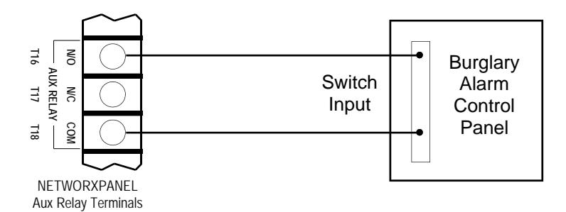
Burglary Alarm Control Panel with Switched Input for Disarming
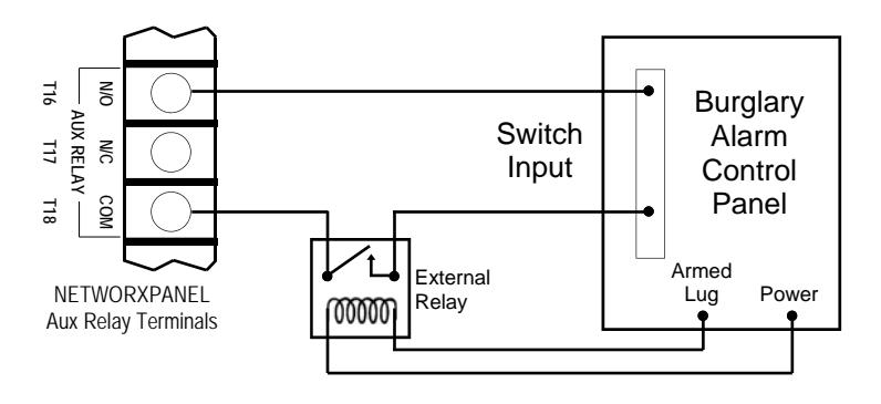
Alarm Panel with Switched Input for Toggled Arm/Disarm
NOTES
3
- 1. Group 1 Disarms a Burglary Alarm Control Panel will always disarm an alarm system. Arming should be performed by other means (such as Alarm Panel Keypad/Schedule).
- 2. Use a qualified electrical/alarm specialist to review your current alarm system and add additional components as needed (such as a relay, wire, resistors, connectors and/or diodes) and re-program the operation of your alarm system as needed.
27
Scheduled Group 4 Enable (Group 1 Activated)
Functions 92 and 93 allow you to set up a window of time where if any Group 1 User Code is entered within this window, Group 4 members will be enabled. (Group 4 members will still need to enter their User Codes to enter). For additional information, see "Group 1 Activated Features" on page 29.
- For day enter: 1 for Sunday, 2 for Monday, 3 for Tuesday, 4 for Wednesday, 5 for Thursday, 6 for Friday, 7 for Saturday, 8 for Monday to Friday, 9 for Saturday and Sunday, and 0 for all days of week.
- Enter time of day in 24-hour format (for example, for 2:15 PM, enter 14:15).
Note: With Functions 92 and 93, if "Two-Door Mode" is enabled, see page 24 " Advanced Two-Door Mode Setup ".
92. Enable Group 4 (Open Time Window)
(This Function enabled through keypad only)
93. Enable Group 4 (Close Time Window)
(This Function enabled through keypad only)
DISABLE RADIO SIGNAL
94. Disable Radio
(This Function enabled through keypad only)
Disables the radio signal (RF) link inside the NETWORXPANEL, rendering all wireless communication with the selected Gateway inoperative.
When using a NETWORXPANEL without the DL-Windows RF link, it is highly recommended to enter this Function to disable all radio access to the NETWORXPANEL. If enrollment in a wireless system should be desired later, simply restart the NETWORX-PANEL either through the use of Function 99 (press ;99;000:), then enroll and reprogram the NET-WORXPANEL through the DL-Windows interface.
95 - 98. Reserved
CLEAR ALL PROGRAMMING
99. Clear All Lock Programming
(This Function enabled through keypad only)
Clears all programming, and returns the NETWORXPANEL to factory default settings. Audit Trail / Log contents are maintained.
; 9 9 ; 0 0 0:
; 9 2 ;[ _ ] ;[ _ _ _ _ ] :
; 9 3 ;[ _ ] ;[ _ _ _ _ ] :
; 9 4 ; 000:
(Day) (Time)
(Day) (Time)
If two NETDK or NETPDK keypads are used in one system, with one keypad designated as the "primary" keypad and the other as "secondary", Function 99 will NOT clear the NETDK / NETPDK keypad memories. To restore the "secondary" keypad to its factory default "primary" state, see WI1856.
3
3
M
Groups and Scheduled Group 1 Examples
The following examples detail the more advanced options within the system. Although all can be programmed using the keypad, when programming becomes more complex you may find it easier to use DL-Windows software to program your NETWORXPANEL. For more information, contact your Alarm Lock security professional.
Assign a User to Two Groups
Create a User 101 (all Users 101-150 are members of Group 2 by default) and include User 101 in Group 3 (as well as the default Group 2).
- 1. Enter Program Mode (if not in already).
- 2. Using Function 2, create User 101 with a User Code of "789":
Press ;2;101;789: .
3. Using Function 35, make User 101 a member of Group 2 and 3: Press ;35;101;23: .
4. Exit Program Mode.
Note: See step 3 above--although User 101 is by default a member of Group 2, you must include Group 2 when using Function 35 or the Group 2 association will be removed.
The example to add Users to Group 2 and Group 3 has been selected due to the fact that Group 1 Activated Functions require that a member of Group 1 enter their User Code to activate the Function, and it may become necessary to assign Users to Groups.
Group 1 Activated Features: Functions 88/89, 90/91 and 92/93
- Function 88 and 89 allow for a window of time to be created where if any Group 1 User Code is entered within the programmed window, Passage Mode will be activated (the system unlocks, allowing passage for all). If a Group 1 User does not enter their User Code during the specified window, Functions 88/89 remain inactive.
- Function 90 and 91 allow for a window of time to be created where if any Group 1 User Code is entered within the programmed window, the AUX Relay will be activated for 2 seconds. This Relay can be used with a Burglary Alarm control panel that has a key switch disarm option. See To Disarm a Burglary Control Panel on page 27. If a Group 1 User does not enter their User Code during the specified window, Functions 90/91 remain inactive.
- Function 92 and 93 allow for a window of time to be created where if any Group 1 User Code is entered within the programmed window, the User Codes in Group 4 will be enabled. If a Group 1 User does not enter their User Code during the specified window, Functions 92/93 remain inactive. Companies typically use this feature to allow Group 1 Managers the ability to enable all Group 4 staff members during a certain window of time.
The following examples illustrate how Functions 88-93 can be programmed via the keypad:
Functions 88/89 : Use Function 88 to set an Open Time Window (during which the Group 1 User must enter their User Code), and then use Function 89 to set the time to close the Window. "Re-lock" the door at night manually (Function 46).
- 1. Enter Program Mode (if not in already).
- 2. Using Function 2, create User 4 with a User Code of "456789":
Press ;2;4;456789: .
- 3. Because User 4 does not have a default Group association, make User 4 a member of Group 1 using Function 35: Press ;35;4;1: .
- 4. Use Function 88 and Function 89 (see page 26) to designate Passage Mode as being between the hours of 8:30 A.M. and 10 A.M. for all days of the week:
Function 88 (Open Window Time) = 8:30 A.M.: Press ;88;0;0830:
Function 89 (Close Window Time) = 10:00 A.M.: Press ;89;0;1000:
5. Exit Program Mode.
The controlled door will now be put in Passage Mode ("unlocked") if User 4 (or any Group 1 member) enters their User Code between 8:30 A.M. and 10 A.M. If a Group 1 User does not enter their User Code during the specified window, Functions 88/89 remain inactive
The controlled door will have to be manually "locked" each night by entering the following command using Function 46:
;46:
- The system can also be programmed to automatically "lock" (disable Passage Mode) each night at 5 P.M. by using Function 73: ; 73 ;0;1700:
- Remember to exit Function Mode when programming is complete.
Groups and Scheduled Group 1 Examples (cont'd.)
Functions 90/91 : Use Function 90 and 91 (see page 27) to create a window of time where if any Group 1 User Code is entered within the programmed window, the AUX Relay will be activated for 2 seconds. The Relay can be configured to disarm a Burglary Alarm control panel (see page 27).
- 1. Enter Program Mode (if not in already).
- 2. Connect AUX Relay to a Burglary Alarm control panel with switch input for disarming.
- 3. Using Function 2, create User 4 with a User Code of "456789": Press ;2;4;456789: .
- 4. Because User 4 does not have a default Group association, make User 4 a member of Group 1 using Function 35:
Press ;35;4;1: .
5. Use Function 90 to set the time to open the window (8:30 A.M. all days of the week) allowing any Group 1 member to close the Relay for 2 seconds. Note: Only 1 Relay closure will occur even if another member of Group 1 enters their User Code. Use Function 91 to set the time to close the window (10 A.M. for all days of the week):
Function 90 (Open Window Time) = 8:30 A.M.: Press ;90;0;0830:
Function 91 (Close Window Time) = 10:00 A.M.: Press ;91;0;1000:
6. Exit Program Mode.
The Relay will close, one time only, when a member of Group 1 enters their User Code between 8:30AM and 10:00AM. If a Group 1 User does not enter their User Code during the specified window, Functions 90/91 remain inactive
The alarm panel will have to be armed at night by the User or by an automatic schedule function of the alarm panel.
Functions 92/93 : Use Function 92 and 93 (see page 28) to create a window of time where if any Group 1 User Code is entered within the programmed window, Group 4 Users will be enabled.
- 1. Enter Program Mode (if not in already).
- 2. Using Function 2, create User 4 with a User Code of "456789":
Press ;2;4;456789: .
3. Because User 4 does not have a default Group association, make User 4 a member of Group 1 using Function 35:
Press ;35;4;1: .
4. Using Function 17, disable Group 4. (Group 4 will need to be "disabled" before it can be "enabled" later).
Press ;17: .
5. Use Function 92 to set the time to open the window (8:30 A.M. all days of the week) allowing any Group 1 member to enable Group 4. Use Function 93 to set the time to close the window (10:00 A.M. all days of the week).
Function 92 (Open Window Time) = 8:30 A.M.: Press ;92;0;0830:
Function 93 (Close Window Time) = 10:00 A.M.: Press ;93;0;1000:
6. Exit Program Mode.
The system will now enable Group 4 User Codes if User 4 (or any Group 1 member) enters their User Code between 8:30 A.M. and 10 A.M. If no Group 1 member arrives to enter their User Code between 8:30 A.M. and 10 A.M., Group 4 User Codes will not be enabled and will remain disabled all day.
The controlled door will have to be manually "locked" each night by entering the following command using Function 82:
; 46 :
The system can also be programmed to automatically disable Group 4 members each night at 5 P.M. by using Function 82:
; 82 ;0;1700:
Test the system by creating User 222 (with User Code 466466) and adding User 222 to Group 4:
;2;222;466466:
;35;222;4:
Remember to exit Function Mode when programming is complete.
Programming Record Sheet
Default Values are shown in parentheses.
|
Function Num-
ber(s) |
Function Name | Programming | |
|---|---|---|---|
| 43/44 | Clock Adjust | +/- 0 0-55 (0) (0) Seconds | |
| 52/53/54 | Pass Time | (3 sec) □ 10 sec □ 15 sec □ | |
| 60 |
Set Keypad Lockout
Attempts |
1-9 Attempts | |
| 61 | Set Keypad Lockout Time | (1) (8) 1-60 seconds | |
| 64/65 | Remote Input Momentary | (Enable) Disable D | |
| 66 | Ambush Code | (9) (9) Ambush Code | |
| 67 | Add Relay/System Features | Check all that apply: 1. Remote Input switch closed and Function 65 Remote Input enabled 2. Remote Input switch closed and Function 64 Remote Input disabled 3. Failed attempted entry 4. Disabled User or Group 5. Follow Access Granted 6. Scheduled Group 1 User Code 7. Scheduled Lock Event 8. Scheduled Unlock Event 9. Keypad Lockout 10. Ambush 11. First Key Press or Proximity Credential 12. Relay on Door Ajar 13. Create Two-Door Mode 24. One Time Access for Group 3 Users 25. Disable Sounder 26. 5 sec. Delayed Entry 27. 15 sec. Delayed Entry 28. 45 sec. Delayed Entry 29. Toggle Passage Mode 30. Forced Unlock Follows Remote Input 31. Follow Access GrantedNo Time Limit 32. Remote Input Disables Unit 34. Forced Lock Follows Remote Input 38. Emergency Commands Enable 39. User Lockout on Emergency 40. Door Ajar Monitor On (default is OFF) | |
| 69/70 | Enter Key | Enable 🗖 (Disable) 🗖 |
|
User Number
(1-5000) |
User Code
(3-6 digits) |
Group
Association |
User Name | ||||||
|---|---|---|---|---|---|---|---|---|---|
| 1 | 2 | 3 | 4 | ||||||
Note:
For a complete list of user codes, obtain a printout from the DL-WINDOWS software.
| Day(s) | Function Name | |||
|---|---|---|---|---|
| Function Number |
Up to 500 scheduled functions can be programmed. For
Day Enter : 1 = Sunday, 2 = Monday, 3 = Tuesday, 4 = Wednesday 5 = Thursday, 6 = Friday, 7 = Saturday, 8 = Monday through Friday, 9 = Saturday and Sunday, 0 = All days of the week Enter time of day in 24-hour format (00:00- 23:59) |
Time | ||
| : | ||||
| : | ||||
| : | ||||
| : | ||||
| : | ||||
| : | ||||
| : | ||||
| : | ||||
| : | ||||
| : | ||||
| : | ||||
| : | ||||
| : | ||||
| : | ||||
| : | ||||
| : | ||||
| : | ||||
| : | ||||
| : | ||||
| : | ||||
| : | ||||
| : | ||||
| : | ||||
| : | ||||
| : | ||||
| : | ||||
| : | ||||
| : | ||||
| : | ||||
| : | ||||
Glossary
ACCESS = Entry into a restricted area.
AMBUSH = A special Code entered at the keypad when the User is forced to unlock a security device. The device unlocks but sends a silent alarm with no indication at the keypad. Can be used to trip a relay, to alert security, or trip a silent alarm on a Burglary Alarm control panel.
AUDIT TRAIL = A date/time stamped log of previous NETWORXPANEL events.
BURGLARY CONTROL PANEL = Provides local alarm and remote communication to request security for burglary/break-in. The integral NETWORX-PANEL relay output used for Ambush can provide a silent alarm and call-for-help.
CLOCK
- REAL TIME CLOCK = An accurate built-in clock that allows date/time stamping of events. The clock can be slowed or speeded up to fine tune long term accuracy to within three minutes per year (see Functions 43 and 44).
- CLOCK SPEED = The clock can be adjusted to allow faster/slower speeds and therefore increasing clock accuracy (see Functions 43 and 44).
CODE = Numeric sequence of numbers (such as: 1234) entered at the keypad. If Star-Enter key is required, must be followed by a : key.
- AMBUSH CODE = See Ambush.
- BASIC USER CODE = User Codes assigned to User Numbers 12+ (except Users 297-300). (Does not allow programming)
- INSTALLER CODE = User Codes assigned to User Numbers 2 and 3. (Allows all programming except Master functions).
- INVALID CODE = A numeric sequence of numbers entered via the keypad buttons that have not been programmed into the lock programming.
- MANAGER CODE = User Codes assigned to User Numbers 4 through 6. (Allows most of the programming functions).
- MASTER CODE = User Code assigned to User Number 1. Default (factory) Master Code is 123456. The User with the Master Code has complete control of the NETWORXPANEL programming.
- QUICK ENABLE USER 300 CODE = Refers to the User Code entered by User 297 which (when entered at the keypad) enables the User Code assigned to User 300 for one time only.
- SERVICE CODE = User 300 User Code. Allows only one entry, then needs to be re-enabled by the User 297 User Code to regain access.
- SUPERVISOR CODE = User Codes assigned to Users 7, 8 and 9. Can only program day-to-day operation.
- USER CODE = Code used by Users. Code is 3 to 6 numeric digits long, allowing controlled entry.
- VALID CODE = A numeric sequence of numbers entered via the keypad buttons that have been programmed in the lock programming and identified by the NETWORXPANEL as a User Code.
DATE = Month, Day and Year entered as MMDDYY.
DAY OF WEEK = Sunday through Saturday (where 1 = Sunday and 7 = Saturday).
DEFAULT = "Default" settings are the original settings that were set at the factory; in other words, it is the original factory condition of the NETWORXPAN-EL, NETPDK or NETDK when it was first taken out of its box.
DISABLE = Turn off.
DOOR AJAR = The controlled door was unlocked and is held open for a certain period of time. If the length of time is longer than the allowed Door Ajar Time (programmed at function 68) the Aux Relay will engage for 2 seconds (function 67 #12) or trigger the Alert Sounder (function 67 #41). Note: The programmed Door Ajar Time begins after the programmed Pass Time ends (Pass Time settings are controlled by Functions 52-54).
DOWNLOAD = Send data to the NETWORXPANEL.
EMERGENCY COMMANDS = For use with all keypads enrolled into the Trilogy Networx™ wireless network only. Wireless commands can be sent to all wireless locking devices in an Account during a crisis or other urgent situation. "Global Lock Down" locks all doors in the Account; "Global Passage" unlocks all doors in the Account; Return all devices in the Account to "normal" discontinues all emergency commands, reverting to "normal" non-emergency operation. Note: DL-Windows does not need to be running to allow these "Emergency" commands to be initiated; any wireless keypad can be used to disseminate these commands throughout the wireless system.
ENABLE = Turn on.
EVENTS = Recorded NETWORXPANEL activity.
Glossary (cont'd)
FUNCTION (also called Programming Functions ) = are the numbers used to program features (enabling/ disabling Users, User Groups, Passage Mode, Schedules, etc.).
GROUP
- USER GROUP = Defining a User to specific Groups, allows User entry when the Group is allowed entry.
- GROUP 1 DISARMS BURGLARY CONTROL PANEL = A Group 1 USER CODE entry can disarm a Burglary Alarm control panel during a predefined schedule. Should the Group 1 try to disarm outside of the scheduled time, the Burglary Alarm control panel will not disarm.
- GROUP 1 ENABLES GROUP 4 USERS = A Group 1 USER CODE entry during a predefined schedule will allow access to Group 4 Users.
- GROUP 1 PUTS UNIT IN PASSAGE = A Group 1 USER CODE entry during a pre-defined schedule will unlock unit.
INSTALLER = See.... CODE, INSTALLER CODE.
-
KEYPAD
= 10-numeric keys,
:
and special
;
key. In addition, since the NETPDK and NETDK models do not possess the internal hardware of a lockset, for the purposes of this manual, the term "keypad" may also be used to describe either the NETPDK or NETDK.
- KEYPAD LOCKOUT = Keypad is programmed to lockout Users, for a specified period of time, when a specified number of invalid User Codes are entered. Note: In Two-Door Mode, "Keypad Lockout" only applies to the individual keypad responsible (Keypad Lockout settings are controlled by Functions 60-61).
- KEYPAD PROGRAMMING = Ability to program the NETWORXPANEL using the keypad.
- KEYPRESS = Pressing a button on the NETPDK or NETDK keypad.
- LEVEL ABILITY = Predefined User types (such as Master, Installer, Manager and Supervisor) have specific abilities to program and/or control the NET-WORXPANEL.
- LOCKOUT ATTEMPTS = (Keypad Lockout) -- A specified number of invalid User Code entries (1-9), that will disable the keypad for a predefined period of time (1-60 seconds).
- LOCKOUT TIME = (Keypad Lockout) -- A predefined time (1-60) seconds that the NETWORXPANEL will
stop accepting User Codes, after a specified number of invalid User Code entries (1-9).
LOG = See... AUDIT TRAIL.
MANAGER = See... CODE, MANAGER CODE.
MASTER = See... CODE, MASTER CODE.
- PASSAGE = Allows anyone to pass through the door without USER CODES (door is unlocked).
- PROGRAM MODE = A mode allowing program / data to be entered through the keypad. Only specific Users can program a NETWORXPANEL manually, by entering their USER CODE, followed by the ; key. To exit program mode, press and hold any keypad key until repeated beeps are heard.
- PROGRAMMABLE RELAY FUNCTIONS = The relay can be programmed for one or more functions.
- RELAY = Switched output allowing remote control of other devices. For an explanation of all relay features, see Function 67 on page 22.
- REMOTE INPUT = Allows entry into the protected area, by the pressing of a normally-open button connected to the NETWORXPANEL REMOTE RE-LEASE INPUT terminals (T26 & T27) by someone on the other side of the door.
- SCHEDULE = A programmed operation (enable/ disable, lock/unlock, etc.) on a specific day (Sunday through Saturday) and time.
- SCHEDULES, QUICK = Any one of four most common types of schedules can be programmed.
- TIME = Hours and Minutes in the HHMM format.
- TIME/DATE STAMP = A recorded date and time that an event occurred.
- TIMEOUT = Immediate operation for a specified number of hours.
- TWO-DOOR MODE = Allows two keypads and/or two Wiegand devices to separately control two doors, with one keypad is designated as the "primary" keypad controlling door number 1, and the other as the "secondary" keypad controlling door number 2.
- UPLOAD = Receive data from the NETWORXPANEL.
- USER = A person who has been provided with a US-ER CODE for access through the door.
- USER LOCKOUT, TOTAL = All Users (except for Master Code) have been locked out and thus are denied access.
ALARM LOCK LIMITED WARRANTY
ALARM LOCK SYSTEMS, INC. (ALARM LOCK) warrants its products to be free from manufacturing defects in materials and workmanship for twenty four months following the date of manufacture. ALARM LOCK will, within said period, at its option, repair or replace any product failing to operate correctly without charge to the original purchaser or user.
This warranty shall not apply to any equipment, or any part thereof, which has been repaired by others, improperly installed, improperly used, abused, altered, damaged, subjected to acts of God, or on which any serial numbers have been altered, defaced or removed. Seller will not be responsible for any dismantling or reinstallation charges, environmental wear and tear, normal maintenance expenses, or shipping and freight expenses required to return products to ALARM LOCK. Additionally, this warranty shall not cover scratches, abrasions or deterioration due to the use of paints, solvents or other chemicals.
THERE ARE NO WARRANTIES, EXPRESS OR IM-PLIED, WHICH EXTEND BEYOND THE DESCRIPTION ON THE FACE HEREOF. THERE IS NO EXPRESS OR IMPLIED WARRANTY OF MERCHANTABILITY OR A WARRANTY OF FITNESS FOR A PARTICULAR PUR-POSE. ADDITIONALLY, THIS WARRANTY IS IN LIEU OF ALL OTHER OBLIGATIONS OR LIABILITIES ON THE PART OF ALARM LOCK.
Any action for breach of warranty, including but not limited to any implied warranty of merchantability, must be brought within the six months following the end of the warranty period.
IN NO CASE SHALL ALARM LOCK BE LIABLE TO ANY-ONE FOR ANY CONSEQUENTIAL OR INCIDENTAL DAMAGES FOR BREACH OF THIS OR ANY OTHER WARRANTY, EXPRESS OR IMPLIED, EVEN IF THE LOSS OR DAMAGE IS CAUSED BY THE SELLER'S OWN NEGLIGENCE OR FAULT.
In case of defect, contact the security professional who installed and maintains your security system. In order to exercise the warranty, the product must be returned by the security professional, shipping costs prepaid and insured to ALARM LOCK. After repair or replacement, ALARM LOCK assumes the cost of returning products under warranty. ALARM LOCK shall have no obligation under this warranty, or otherwise, if the product has been repaired by others, improperly installed, improperly used, abused, altered, damaged, subjected to accident, nuisance, flood, fire or acts of God, or on which any serial numbers have been altered, defaced or removed. ALARM LOCK will not be responsible for any dismantling, reassembly or reinstallation charges, environmental wear and tear, normal maintenance expenses, or shipping and freight expenses required to return products to ALARM LOCK. Additionally, this warranty shall not cover scratches, abrasions or deterioration due to the use of paints, solvents or other chemicals.
This warranty contains the entire warranty. It is the sole warranty and any prior agreements or representations, whether oral or written, are either merged herein or are expressly cancelled. ALARM LOCK neither assumes, nor authorizes any other person purporting to act on its behalf to modify, to change, or to assume for it, any other warranty or liability concerning its products.
In no event shall ALARM LOCK be liable for an amount in excess of ALARM LOCK's original selling price of the product, for any loss or damage, whether direct, indirect, incidental, consequential, or otherwise arising out of any failure of the product. Seller's warranty, as hereinabove set forth, shall not be enlarged, diminished or affected by and no obligation or liability shall arise or grow out of Seller's rendering of technical advice or service in connection with Buyer's order of the goods furnished hereunder.
ALARM LOCK RECOMMENDS THAT THE ENTIRE SYS-TEM BE COMPLETELY TESTED WEEKLY.
Warning: Despite frequent testing, and due to, but not limited to, any or all of the following; criminal tampering, electrical or communications disruption, it is possible for the system to fail to perform as expected. ALARM LOCK does not represent that the product/system may not be compromised or circumvented; or that the product or system will prevent any personal injury or property loss by burglary, robbery, fire or otherwise; nor that the product or system will in all cases provide adequate warning or protection. A properly installed and maintained alarm may only reduce risk of burglary, robbery, fire or otherwise but it is not insurance or a guarantee that these events will not occur. CONSEQUENTLY, SELLER SHALL HAVE NO LIA-BILITY FOR ANY PERSONAL INJURY, PROPERTY DAMAGE, OR OTHER LOSS BASED ON A CLAIM THE PRODUCT FAILED TO GIVE WARNING. Therefore, the installer should in turn advise the consumer to take any and all precautions for his or her safety including, but not limited to, fleeing the premises and calling police or fire department, in order to mitigate the possibilities of harm and/or damage.
ALARM LOCK is not an insurer of either the property or safety of the user's family or employees, and limits its liability for any loss or damage including incidental or consequential damages to ALARM LOCK's original selling price of the product regardless of the cause of such loss or damage.
Some states do not allow limitations on how long an implied warranty lasts or do not allow the exclusion or limitation of incidental or consequential damages, or differentiate in their treatment of limitations of liability for ordinary or gross negligence, so the above limitations or exclusions may not apply to you. This Warranty gives you specific legal rights and you may also have other rights which vary from state to state.