Alarm Lock DL3500DB, DL3500CR, Installation Instructions
Open the original PDF document
View PDF
ALARM LOCK SYSTEMS, INC. A division of the NAPCO Security Group 345 Bayview Avenue, Amityville, NY 11701 (631) 789-4871 1-800-252-5625 Fax: (631) 789-3383
© 2000, Alarm Lock TRILOGY is a registered trademark of Alarm Lock.
TECH SUPPORT: 1-800-ALA-LOCK
Part No. WI 1004 1/00
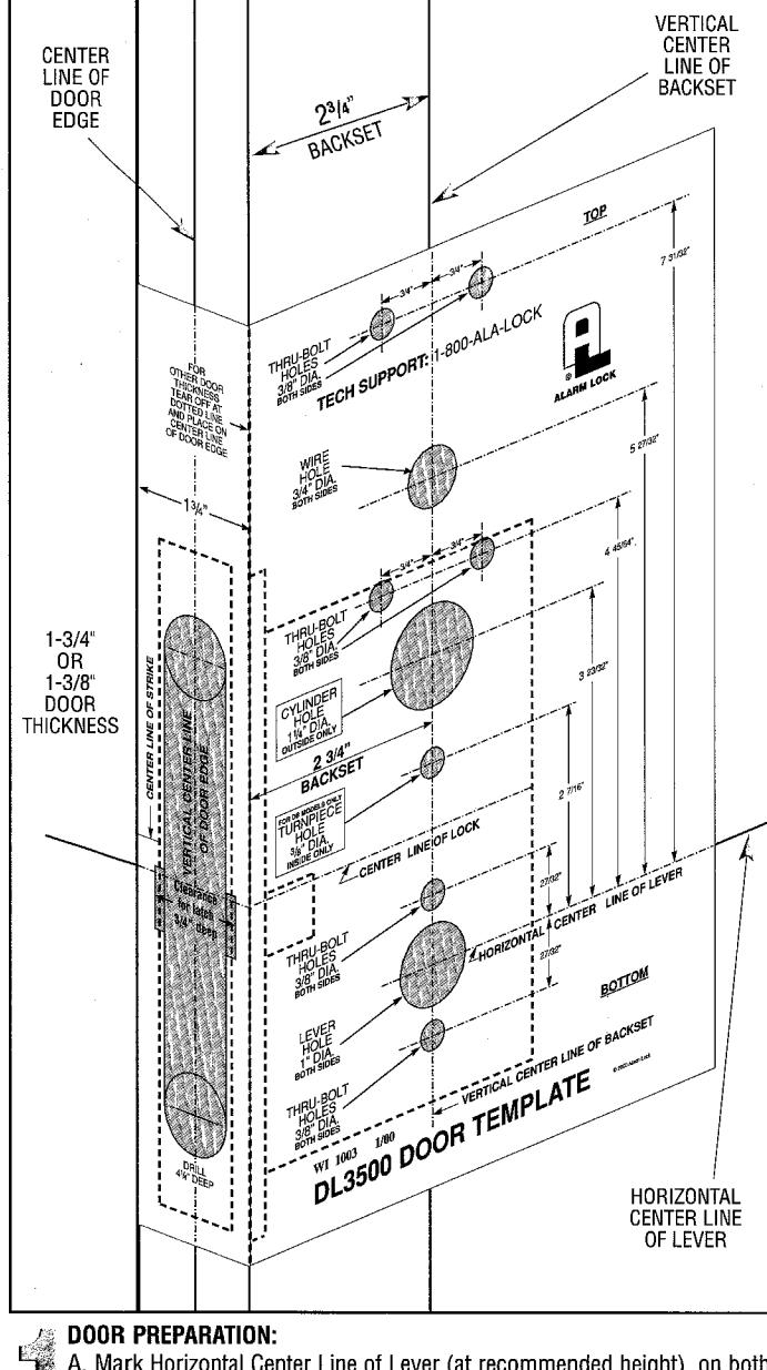
- A. Mark Horizontal Center Line of Lever (at recommended height) on both sides of door. Mark Vertical Center Line of Door edge. Mark Vertical Center Line of Backset (2-3/4") on both sides of door.
- B. Tape template in position on door, lining up with horizontal and vertical lines.
- C. Mark all hole centers on each side of door as per template.
- D. Mortise for lock and lock front in center of door edge as per template.
- E. Drill all holes as required. It is recommended that all through holes be drilled from each side to avoid splintering
METAL DOORS require horizontal and vertical lock case support provided by door manufacturer.

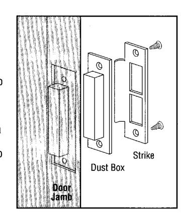
A. Position strike on door jamb and trace. Strike center line should be 3/8" above lock's center line.
- B. Mortise into door jamb deep enough for dust box.
- C. If dust box is not used, mortise deep enough to allow latchbolt and dead bolt to fully extend.
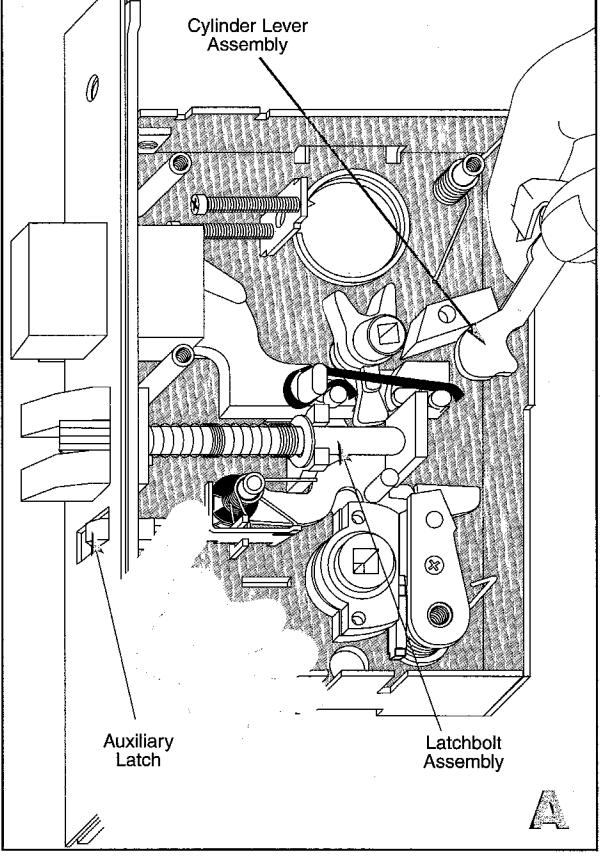
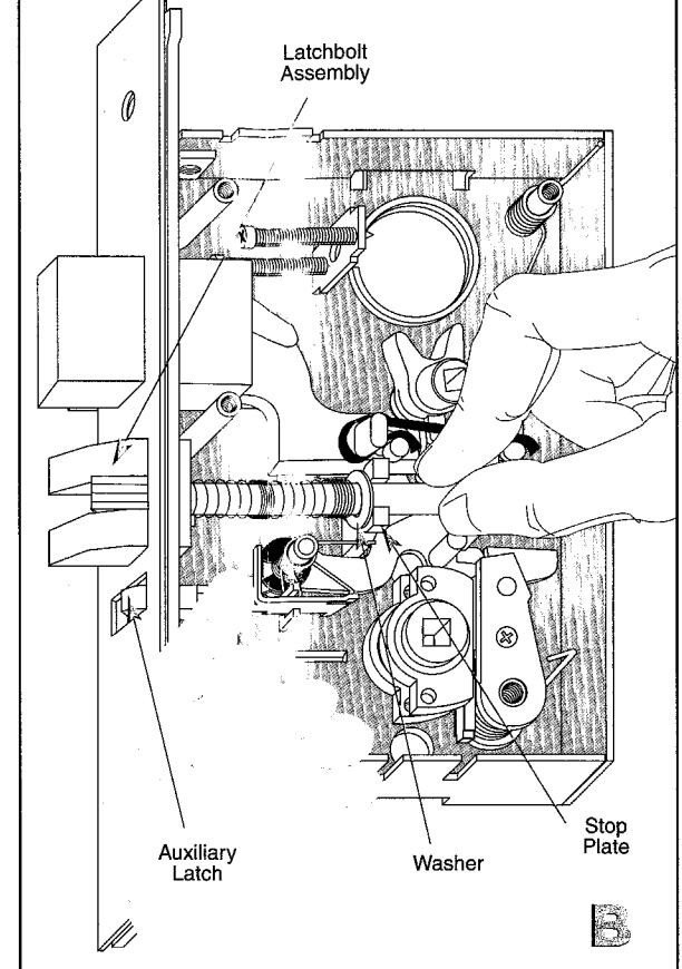
IF REVERSE HANDING IS REQUIRED: Remove lock cover. A. Lift out Cylinder Lever Assembly. Pull back Auxiliary latch and hold. B. Lift up Latchbolt and remove, rotate and replace (Compress latchbolt spring with washer which should
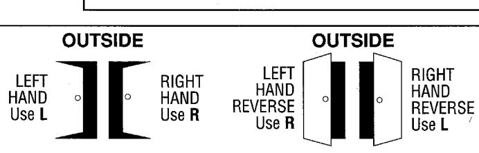
WHEN CHANGING HANDING PROPER STRIKE IS REQUIRED
be in front of Stop Plate). Replace Cylinder Lever
Assembly. Replace cover and fasten with 5 screws.
PREPARTOR FOR STORY OF THE PROPERTY OF THE PROPERTY OF THE PROPERTY OF THE PROPERTY OF THE PROPERTY OF THE PROPERTY OF THE PROPERTY OF THE PROPERTY OF THE PROPERTY OF THE PROPERTY OF THE PROPERTY OF THE PROPERTY OF THE PROPERTY OF THE PROPERTY OF THE PROPERTY OF THE PROPERTY OF THE PROPERTY OF THE PROPERTY OF THE PROPERTY OF THE PROPERTY OF THE PROPERTY OF THE PROPERTY OF THE PROPERTY OF THE PROPERTY OF THE PROPERTY OF THE PROPERTY OF THE PROPERTY OF THE PROPERTY OF THE PROPERTY OF THE PROPERTY OF THE PROPERTY OF THE PROPERTY OF THE PROPERTY OF THE PROPERTY OF THE PROPERTY OF THE PROPERTY OF THE PROPERTY OF THE PROPERTY OF THE PROPERTY OF THE PROPERTY OF THE PROPERTY OF THE PROPERTY OF THE PROPERTY OF THE PROPERTY OF THE PROPERTY OF THE PROPERTY OF THE PROPERTY OF THE PROPERTY OF THE PROPERTY OF THE PROPERTY OF THE PROPERTY OF THE PROPERTY OF THE PROPERTY OF THE PROPERTY OF THE PROPERTY OF THE PROPERTY OF THE PROPERTY OF THE PROPERTY OF THE PROPERTY OF THE PROPERTY OF THE PROPERTY OF THE PROPERTY OF THE PROPERTY OF THE PROPERTY OF THE PROPERTY OF THE PROPERTY OF THE PROPERTY OF THE PROPERTY OF THE PROPERTY OF THE PROPERTY OF THE PROPERTY OF THE PROPERTY OF THE PROPERTY OF THE PROPERTY OF THE PROPERTY OF THE PROPERTY OF THE PROPERTY OF THE PROPERTY OF THE PROPERTY OF THE PROPERTY OF THE PROPERTY OF THE PROPERTY OF THE PROPERTY OF THE PROPERTY OF THE PROPERTY OF THE PROPERTY OF THE PROPERTY OF THE PROPERTY OF THE PROPERTY OF THE PROPERTY OF THE PROPERTY OF THE PROPERTY OF THE PROPERTY OF THE PROPERTY OF THE PROPERTY OF THE PROPERTY OF THE PROPERTY OF THE PROPERTY OF THE PROPERTY OF THE PROPERTY OF THE PROPERTY OF THE PROPERTY OF THE PROPERTY OF THE PROPERTY OF THE PROPERTY OF THE PROPERTY OF THE PROPERTY OF THE PROPERTY OF THE PROPERTY OF THE PROPERTY OF THE PROPERTY OF THE PROPERTY OF THE PROPERTY OF THE PROPERTY OF THE PROPERTY OF THE PROPERTY OF THE PROPERTY OF THE PROPERTY OF THE PROPERTY OF THE PROPERTY OF THE PROPERTY OF THE PROPERTY OF THE PROPERTY OF THE PROPERTY OF THE PROPERTY OF THE PROPERTY OF THE PRO
INSTALLING LOCK AND OUTSIDE TRIM ASSEMBLY
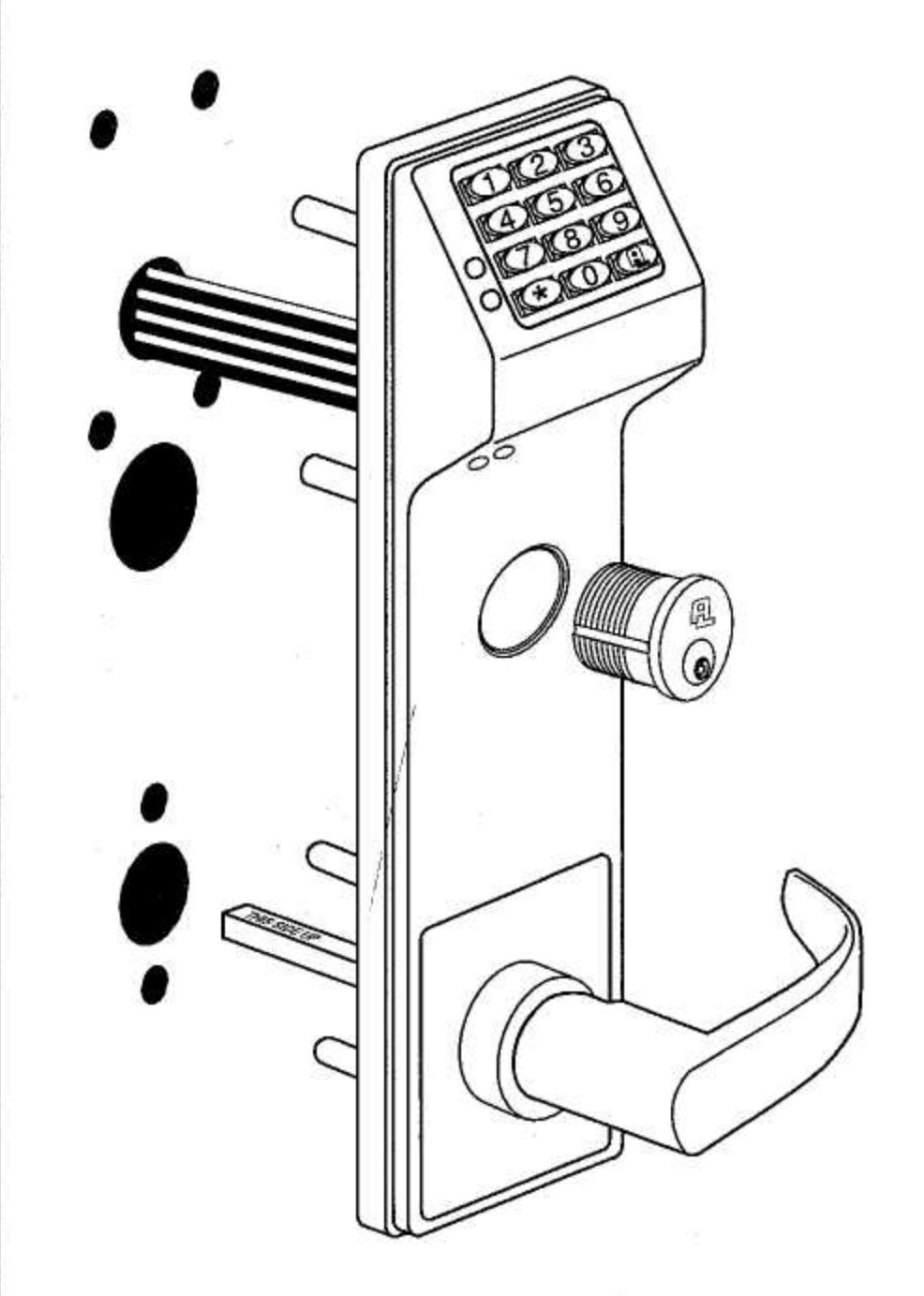
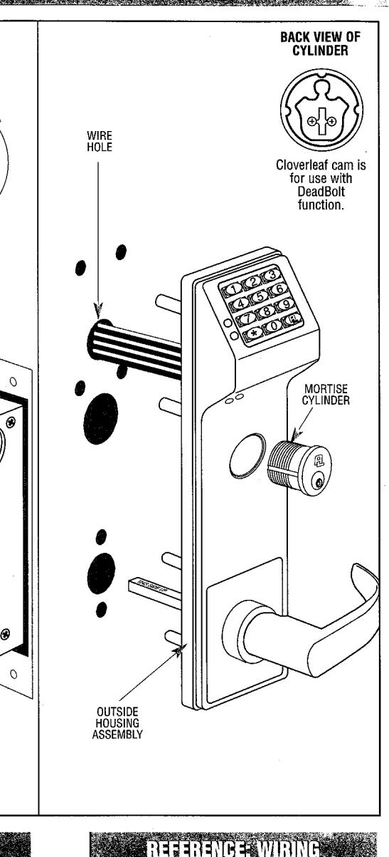
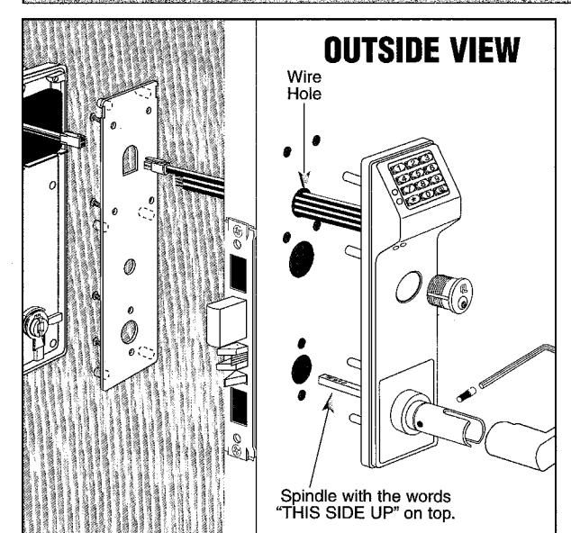
- A. Insert lock into cavity and fasten with 2 screws. B. Push all wires through Wire Hole in door and place Outside
- Housing Assembly on door and through lock.
- C. Spindle position must be with words "THIS SIDE UP" on top.
INSTALLING CYLINDER AND LEVER
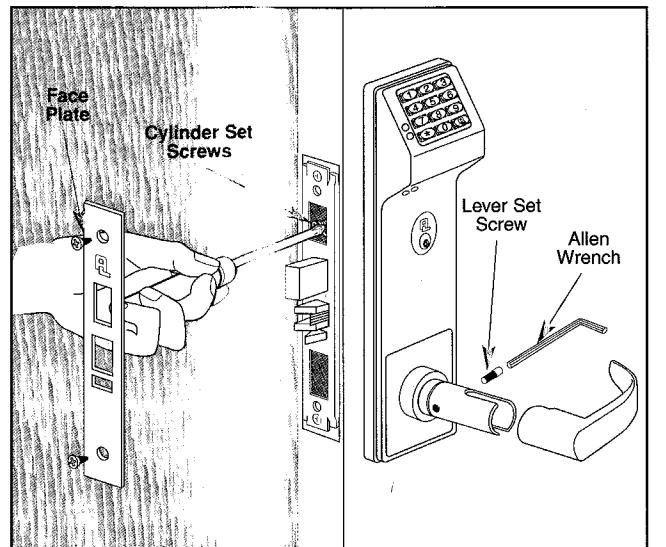
- A. Thread Cylinder through Outside Assembly and tighten up as far as possible. Make sure keyway is at bottom of cylinder.
- C. Tighten the Cylinder Set Screw nearest the cylinder. D. Position and fasten faceplate with 2 screws.
- E. Slide lever on spindle and fasten with Lever Set Screw.
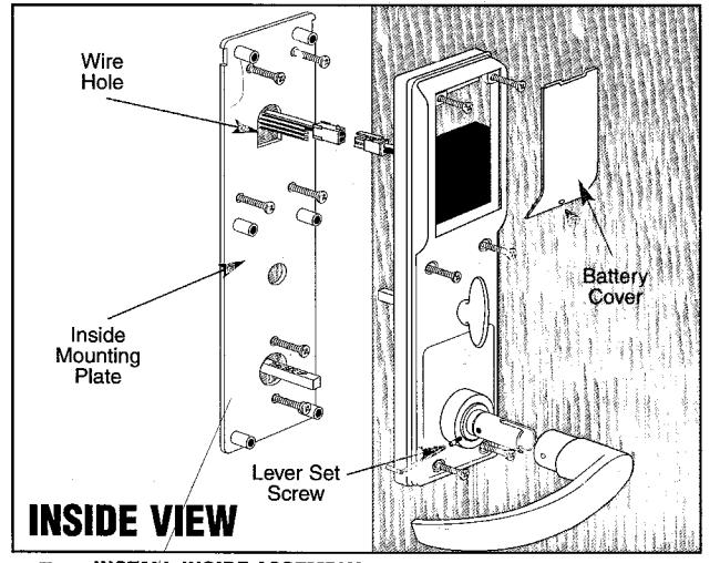
INSTALL INSIDE ASSEMBLY
A. Pull all wires through wire hole and Inside Mounting Plate. B. Position and fasten Inside Mounting Plate with 6 screws.
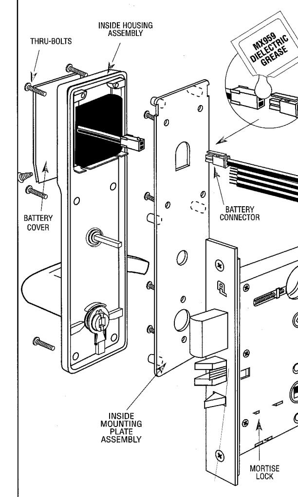
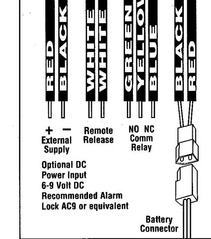
Do not pinch or cut wires. C. Position Inside Housing Assembly on door and fasten with 6 screws. D. Align and plug together Battery Connector. Seal with Dielectric Grease BEFORE CLOSING
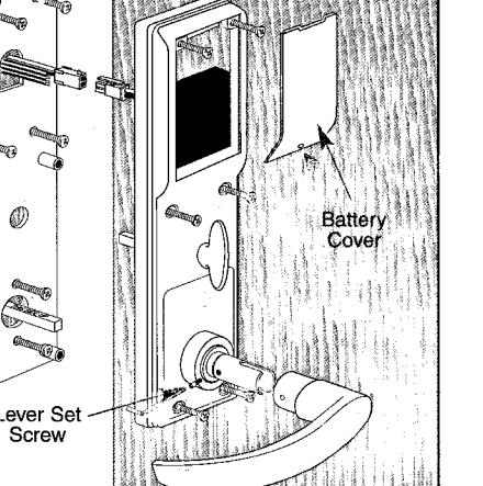
included. Fold wires and slide battery case into Inside Housing assembly. DOOR TEST LOCK E. Position and fasten Battery Cover with 1 screw.
F. Slide lever on spindle and fasten with Lever Set Screw.
FOR PROPER OPERATION

DL3500CR (ClassRoom)
The Keyless, Electronic Mortise Lockset INSTALLATION INSTRUCTIONS
ALARM LOCK SYSTEMS, INC.
A division of the NAPCO Security Group 345 Bayview Avenue, Amityville, NY 11701 (631) 789-4871 1-800-252-5625
Fax: (631) 789-3383
© 2000, Alarm Lock TRILOGY is a registered trademark of Alarm Lock.
TECH SUPPORT: 1-800-ALA-LOCK
Part No. WI 1004 1/00
PREPARING DOOR FOR INSTALLATION
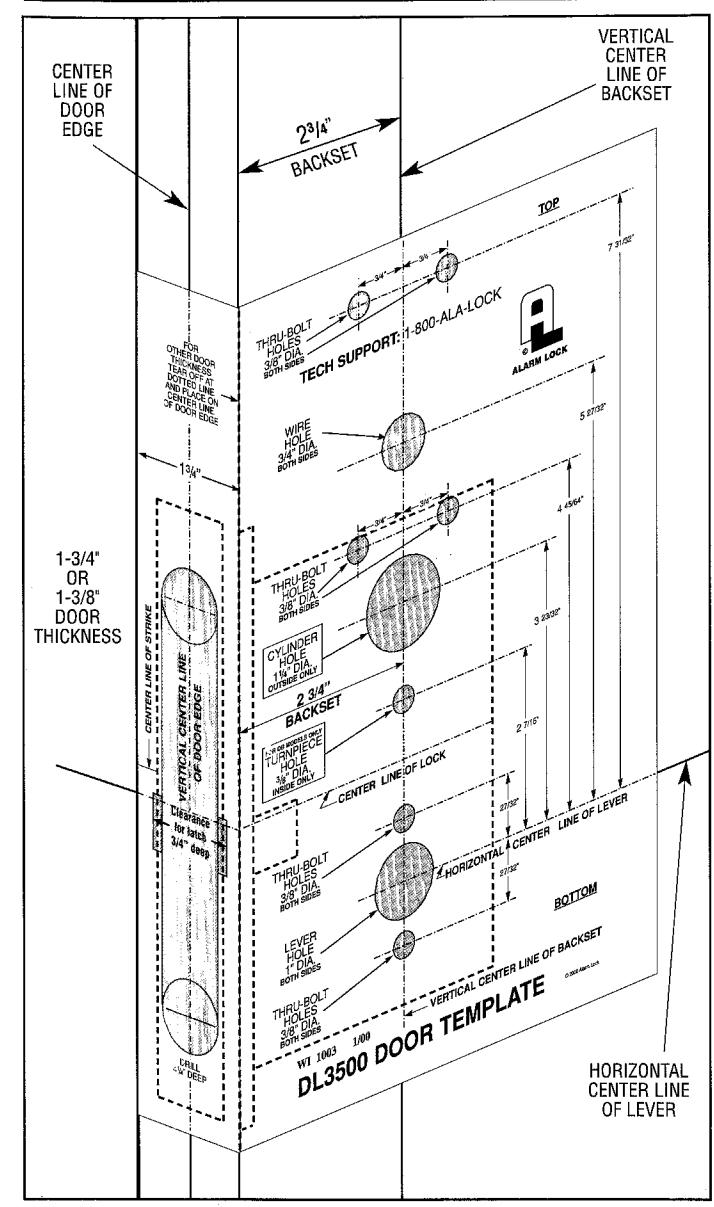
DOOR PREPARATION:
- A. Mark Horizontal Center Line of Lever (at recommended height) on both sides of door. Mark Vertical Center Line of Door edge. Mark Vertical Center Line of Backset (2-3/4") on both sides of door.
- B. Tape template in position on door, lining up with horizontal and vertical lines. C. Mark all hole centers on each side of door as per template.
- D. Mortise for lock and lock front in center of door edge as per template.
- E. Drill all holes as required. It is recommended that all through holes be drilled from each side to avoid splintering
METAL DOORS require horizontal and vertical lock case support provided by door manufacturer.

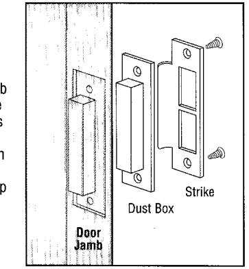
- Position strike on door jamb and trace. Strike center line should be 3/8" above lock's center line.
- B. Mortise into door jamb deep enough for dust box.
- C. If dust box is not used, mortise deep enough to allow latchbolt and dead bolt to fully extend.
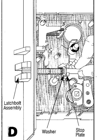
IF REVERSE HANDING IS REQUIRED:
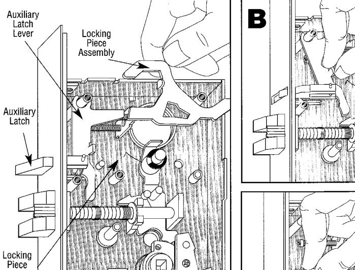
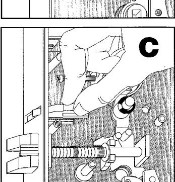
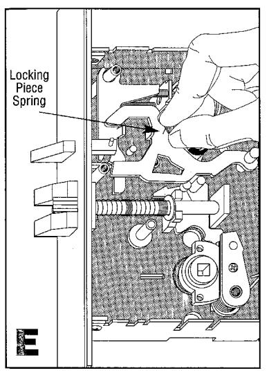
Spring Remove lock cover.
- A. Remove spring from Locking Piece Assembly and lift Assembly out.
- B. Pull back Auxiliary Latch Lever.
IF REVERSE HANDING IS
- C. Disengage, rotate and re-engage Auxiliary Latch.
- D. Lift up Latchbolt and remove, rotate and replace (Compress latchbolt spring with washer which should be in front of Stop Plate.
- E. Replace Locking Piece assembly and spring REQUIRED: Replace cover and fasten with 5 screws.
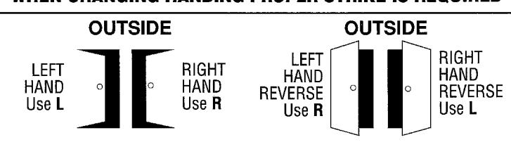
WHEN CHANGING HANDING PROPER STRIKE IS REQUIRED
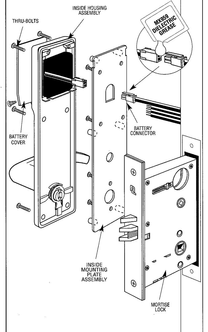
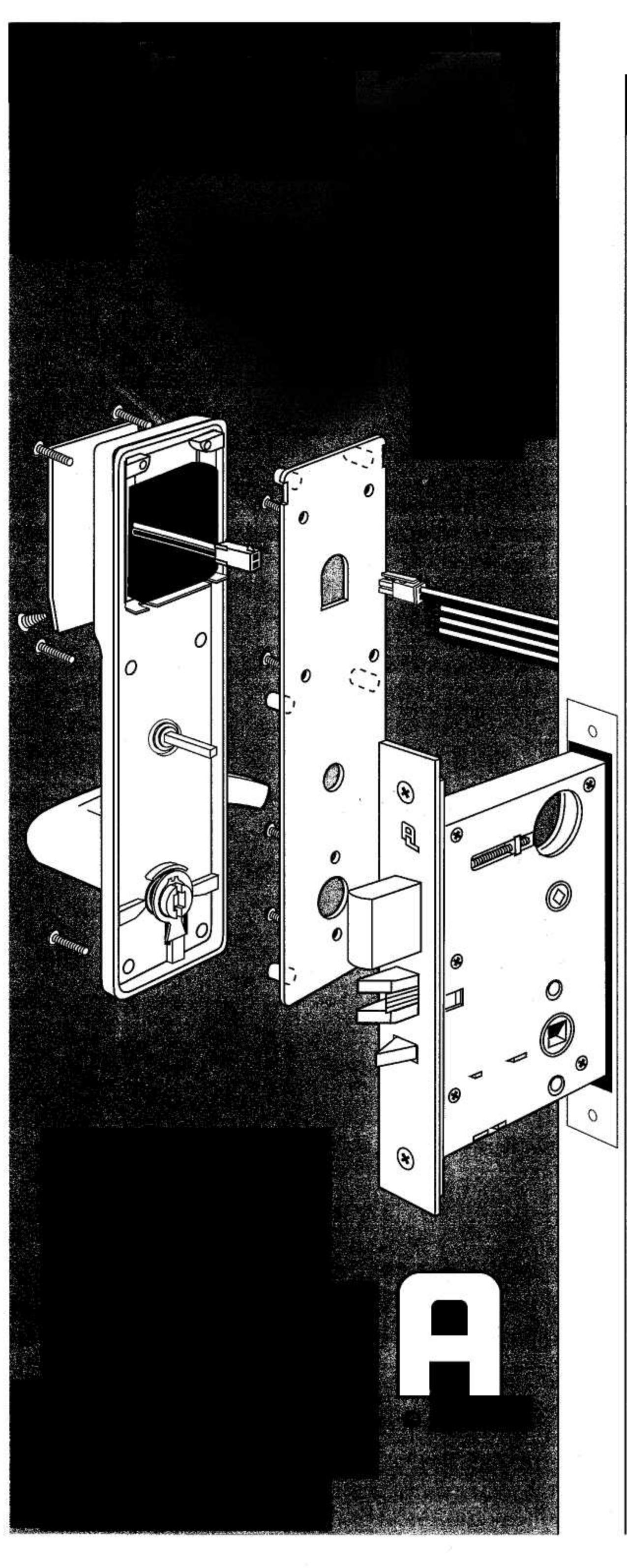
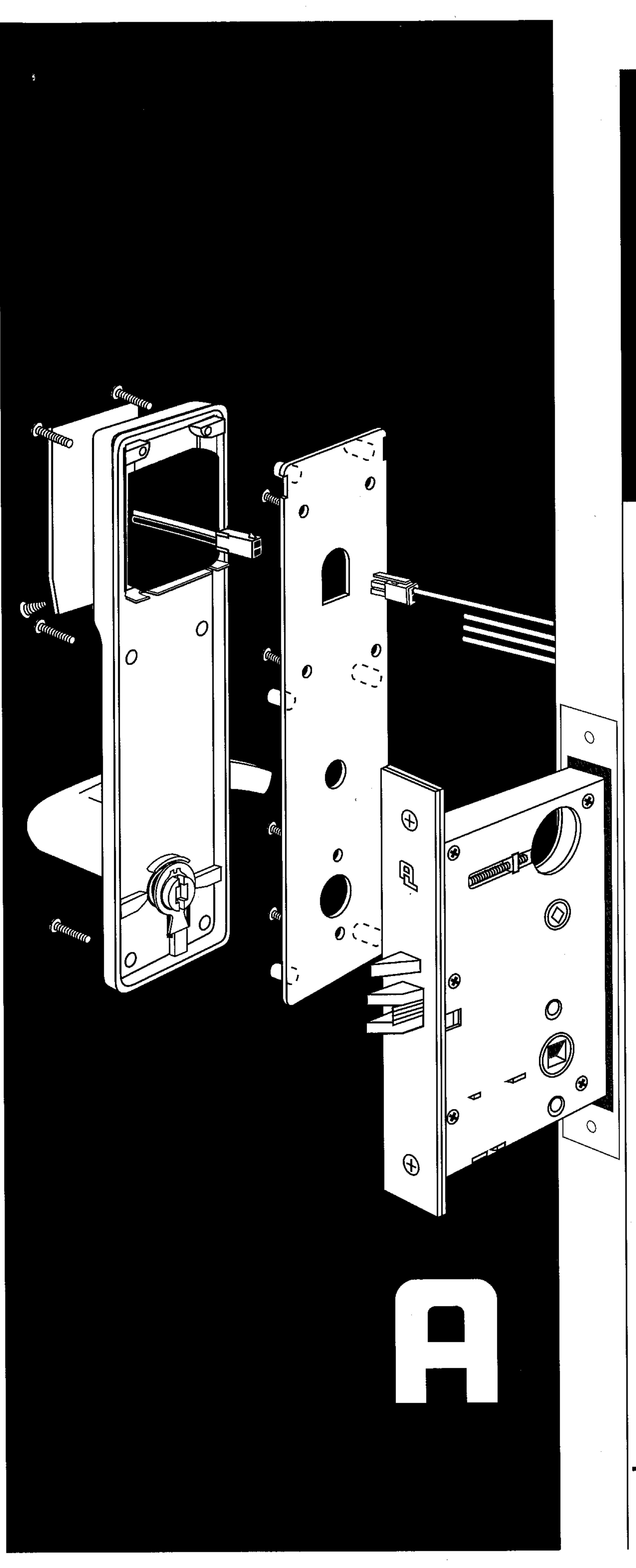
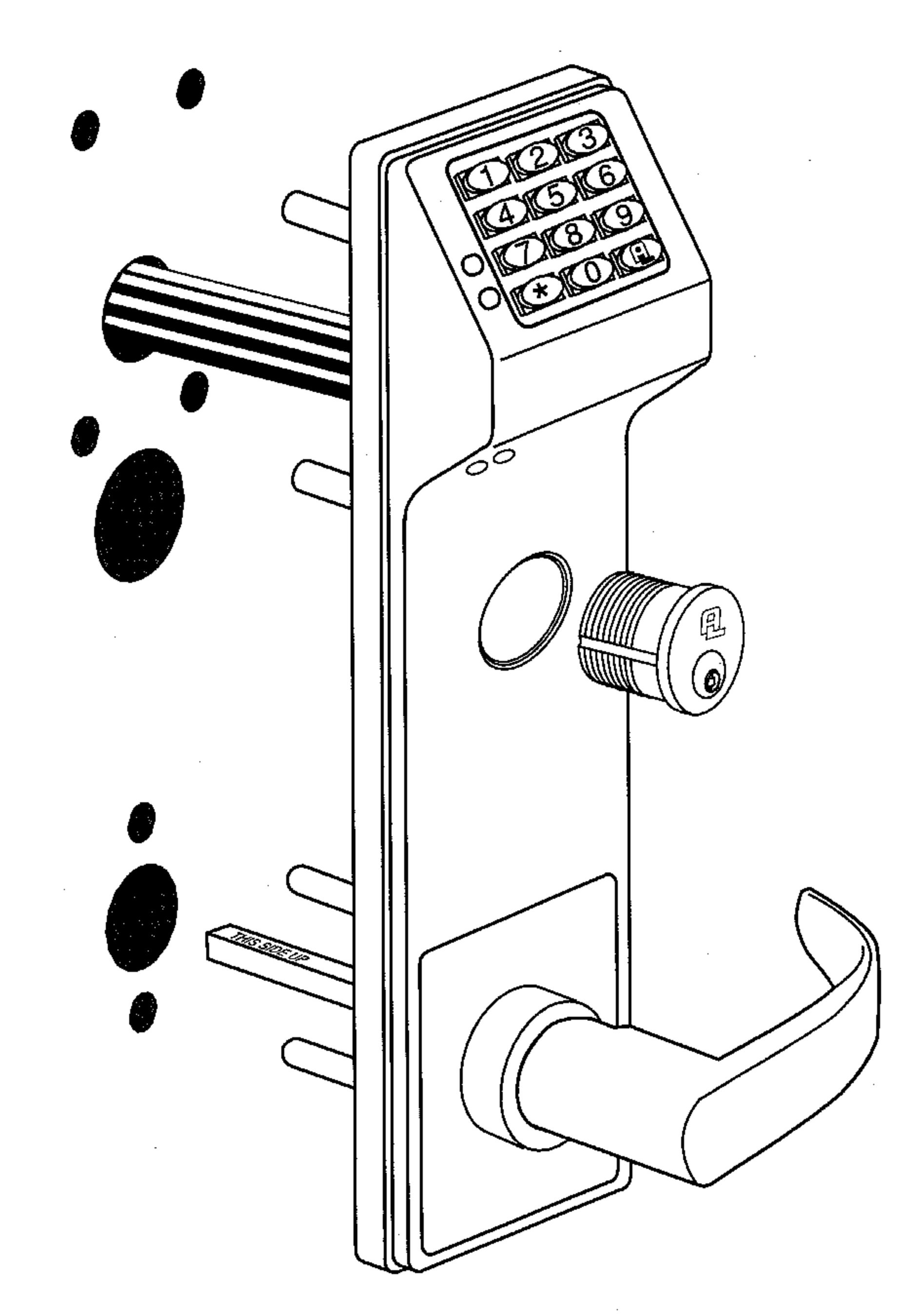
REFERENCE: EXPLODED VIEW
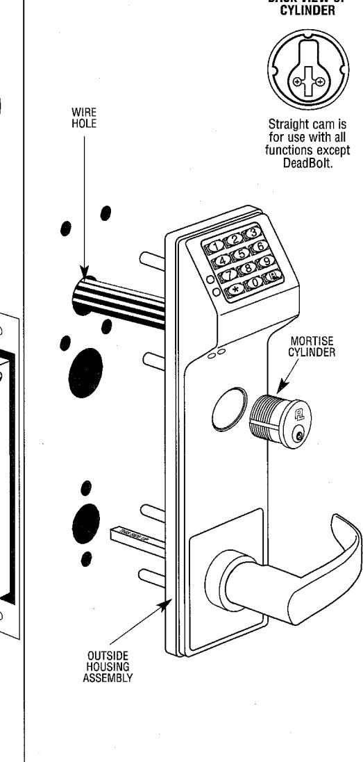
PREPARING LOCK FOR INSTALLATION:
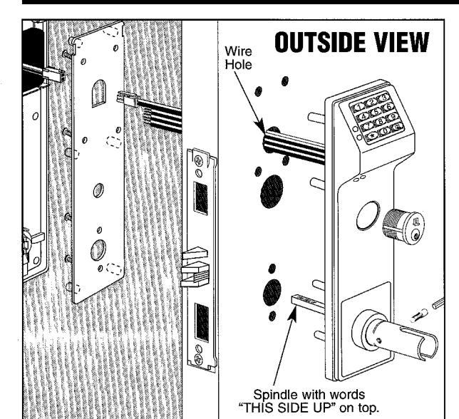
INSTALLING LOCK AND OUTSIDE TRIM ASSEMBLY Insert lock into cavity and fasten with 2 screws.
- Push all wires through Wire Hole in door and place Outside Housing Assembly on door and through lock.
- C. Spindle position must be with words "THIS SIDE UP" on top.
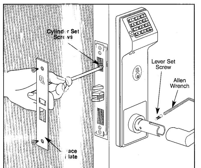
INSTALLING CYLINDER AND LEVER A. Thread Cylinder through Outside Assembly and tighten up as far as possible. Make sure keyway is at the bottom of cylinder.
- C. Tighten the Cylinder Set Screw nearest the cylinder. D. Position and fasten faceplate with 2 screws.
- E. Slide lever on spindle and fasten with the Lever Set Screw.
INSTALL INSIDE ASSEMBLY
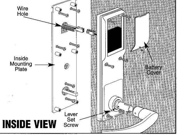
- A. Pull all wires through wire hole and Inside Mounting Plate. B. Position and fasten Inside Mounting Plate with 6 screws. Do not pinch or cut wires.
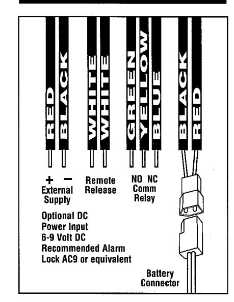
- C. Position Inside Housing Assembly on door and fasten with 6 screws. D. Align and plug together Battery Connector. Seal with Dielectric Grease included. Fold wires and slide battery case into Inside Housing assembly.
- E. Position and fasten Battery Cover with 1 screw. F. Slide lever on spindle and fasten with the Lever Set Screw.
REFERENCE: WIRING
BEFORE CLOSING DOOR TEST LOCK FOR PROPER OPERATION