Alarm Lock DL1300NW & PDL1300NW Narrow Stile Mounting and Installation Instructions
Open the original PDF document
View PDF

DL1300NW & PDL1300NW
NARROW STILE ACCESS LOCKS
MOUNTING AND INSTALLATION INSTRUCTIONS
345 Bayview Avenue, Amityville, New York 11701 For Sales and Repairs 1-800-ALA-LOCK For Technical Service 1-800-645-9440 or visit us at <a href="http://lech.napcosecurity.com/">http://lech.napcosecurity.com/</a>\ne Technical Service is for security professionals onl Publicly traded on NASDAQ Symbol: NSSC
© ALARM LOCK 2017
GENERAL DESCRIPTION
The DL1300NW and PDL1300NW are keypad programmable or wirelessly programmable (through DL-Windows software) narrow stile entry trim for Adams Rite ® 4510, 4530, 4710, 4730 and 4900 deadlatch locks, and 1850, 1950, 4070, MS1850S and MS1950S series deadbolts for narrow stile aluminum doors*. Models DL1325NW, DL1350NW, PDL1325NW and PDL1350NW are for use with Adams Rite MS1850S, MS1950, MS1850S-050 and MS1950-050.
The DL1300NW and PDL1300NW will retract the existing Adams Rite® latch when an access code is entered (or a credential is presented) and the lever is pressed down (or the tumpiece turned). The trim is designed to operate with any Adams Rite® interior device such as a "pushpaddle" or lever. Because Adams Rite® trim exists on the inside, the "hold-back feature remains operational for a continuous unlatched function (see Adams Rite® instructions). Entering a passage mode function code activates latched passage mode (device is unlocked but the lever or tumpiece is engaged continuously) until another passage mode function code is entered, re-locking the trim. All locks are equipped with a mechanical metal key override. For programming information, visit our Technical Library at <a href="http://tech.napcosecurity.com/">http://tech.napcosecurity.com/</a> and download programming instructions for the PDL1300NW (WI2258) and DL1300NW (WI2264).
MECHANICAL FEATURES
The overall enclosure housing is 15-5/16" inches high, 1-5/8" inches deep and " inches wide. The trim is through-bolted to the stile of the door (using four #10 screws) and are secured on the interior side of the door. Supported stile thickness is ".
- DL1300NW and PDL1300NW models support 5000 users and includes 36,000-event audit trail and 500 event schedule. Keypad or PC programmable
- Aluminum door retrofit outside trim for Adams Rite<sup>®</sup> 1850, 1950, 4710, 4070, 4730, 4900, MS1850S and MS1950S Series locks
- All-metal, vandal-resistant 12-button keypad supports 3-6 digit PIN codes, and multilevel user hierarchy (master, manager, supervisor and basic users)
- Keypad or PC programmable (see model information). Quickly and easily add or delete users and enter "passage mode", service codes, group lock-out & group-enable
- PDL1300NW supports proximity ID cards, keyfobs and proximity tags with its integral proximity reader (high securi-
ty applications can require use of both PIN code plus proximity credential for access)
WI2257LF 10/17
- Real time clock and PC programmable automatic lock/ unlock scheduling for 500 events
- Wide weatherproof operating range from -31°F to 151°F (-35°C to 66°C)
- Provides 50,000 operations using 4AA batteries; includes audible and visual low battery alert
- Non-handed; fully field-reversible
- Mechanical key override; interchangeable cores supported (Corbin/Russwin, Yale, Schlage, Medeco)
- Mortise Cylinder, 1-½" supplied (supports 1-1/8", 1-½", 1-3/8" and 1-½"
- Backsets 31/32",1-1/8" and 1-½"; stile thickness 1-¾"
TABLE OF CONTENTS
| ., | |
|---|---|
| GENERAL DESCRIPTION1 | |
| MECHANICAL FEATURES1 | |
| MOUNTING AND INSTALLATION 2 | |
| INSTALL CYLINDER3 | } |
| SET DOOR "HAND"3 | } |
| INSTALL LEVER4 | ļ |
| INSERT INTERFACE CYLINDER4 | - |
| INSTALL LOCK6 | ò |
| CONNECT BATTERIES6 | ò |
| TEST OPERATION7 | , |
| ALARM LOCK LIMITED WARRANTY 8 | ₹ |
MOUNTING AND INSTALLATION
For factory prepped doors , use dimensions shown. Dimensions are referenced from center of 1-¼" cylinder hole. The Adams Rite lock determines the backset.
When mounting the new Adams Rite locks:
- Do not install the outside cylinder -- this trim replaces it;
- Do not install the faceplate (access to the cylinder set screw in the lock is required during mounting and installation).
Mechanical Override Cylinder Cams
The DL1300NW and PDL1300NW trim requires the use of an oval Alarm Lock cam (supplied with cylinder). For other manufacturers, please see the charts below.
| Cams for Standard Mortise Cylinders | ||
|---|---|---|
| Corbin-Russwin | HW1344 | |
| Marks | HW1346 | |
| Arrow | HW1348 | |
| Sargent | HW1348 | |
| Schlage | HW1349 | |
| Cams for IC Mortise Cylinders | ||
|---|---|---|
|
S6169-10B*
S6169-26D* |
||
| HW1343 | ||
| HW1345 | ||
| HW1347 | ||
| HW1350 | ||
| HW1351 | ||
* All other IC cylinder preps must provide their own IC housing, but order the appropriate cam from Alarm Lock.
| Cylinder Length | Collar P/N |
|---|---|
| 1-⅜ | HW1331 |
| 1-½ | HW1342 |
Cylinder Collars:
The DL1300NW and PDL1300NW can use a 1-⅛" & 1-¼" mortise cylinder without the use of a collar (1-¼" requires two plastic spacers, supplied). For cylinders longer than 1-¼" a collar is required.
Order collars from an Alarm Lock distributor.
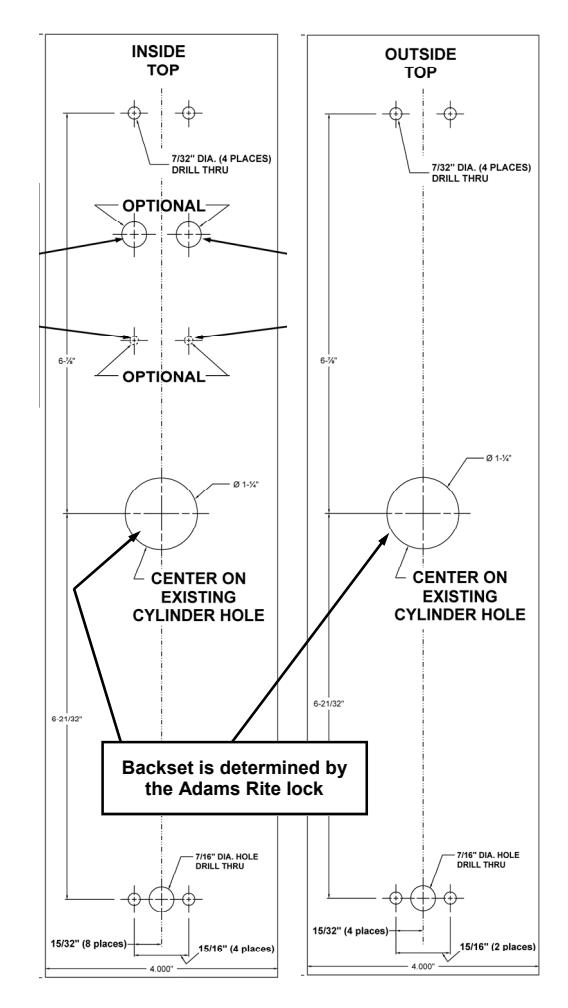
Template (use WI1459)
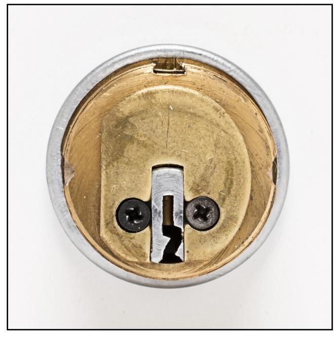
Cam for Mechanical Override Cylinder
Install Cylinder
1. Install Cylinder if not already installed at the factory. Screws A & B (see Fig. 1) are correctly set at factory. If it is difficult to screw in the cylinder, loosen the two screws near the actuator (A) one turn. If you find the cylinder is still difficult to screw in, then loosen the other screws (B) one turn. Do not loosen the screws all the way or it may be difficult to replace them properly!
Note: The trim is manufactured to use a 1-1/8" or 1-¼" Alarm Lock mortise cylinder with a HW-1302 cam. If the cylinder that will be used is longer than 1-¼", a collar must be utilized. Please see the collar information on the previous page.
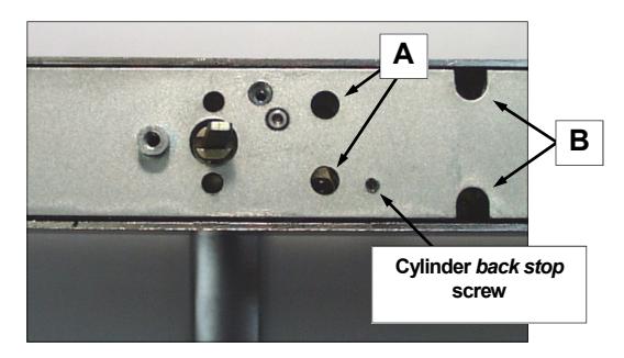
Fig. 1: Install Cylinder if not already installed at the factory
1a. Insert key half-way into the cylinder, then screw it in.
See Fig. 1a. If cylinder will not seat flush, the cylinder back stop screw may require loosening. Cylinders that are longer than 1-¼" will require a collar, which will stick out from the surface when correctly installed. Please
see the cylinder information on the previous page.
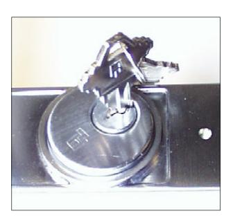
Fig. 1a: Insert key 1/2 way into cylinder and screw in
1b. After the cylinder is screwed in all the way, center the keyway toward the bottom (see Fig. 1b). If an interchangeable core cylinder is utilized, then center the interface toward the bottom. Tighten the screws that were loosened in step 1.
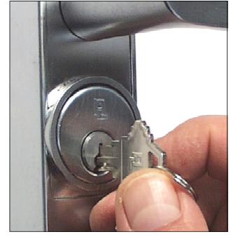
Fig. 1b: Center keyway toward bottom
1c. Remove the key. Use a 1/16" hex wrench to screw the cylinder back stop screw in fully. (See Fig. 1c) The key should now only rotate counterclockwise .
NOTE: To remove cylinder, reverse steps 1a-1c.
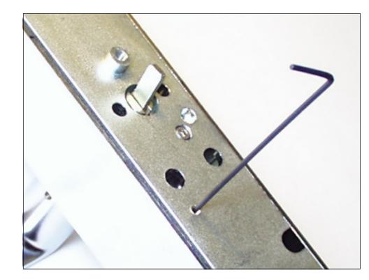
Fig. 1c: Use 1/16" hex wrench to screw in the cylinder back stop screw
Setting the Door "Hand"
2. With the key always on the outside, the door hand is generally determined by the location of the hinges- hinges are either inside or outside. See Fig. 2.
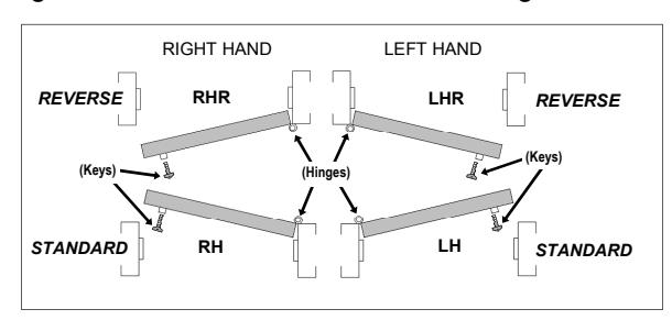
Fig. 2: Cross Section Top View -- Door Hand
2a. Select the Interface Cylinder/Adapter
After setting the door "hand", select the left or right Interface adapter to match the door "handing". Fig. 2a shows the left and right hand interface cylinders.
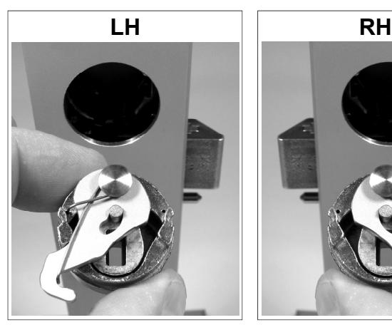
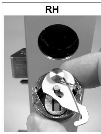
Fig. 2a: LH and RH orientation for Interface cylinder.
Install the Lever
3. Install the lever with proper orientation for the lock/door hand used. Tighten the set screw using a 1/8" hex wrench (see Fig. 3).
IMPORTANT! The top of the set screw must be at (or below) lever surface. If not, check to ensure the lever is fully pushed toward the trim.
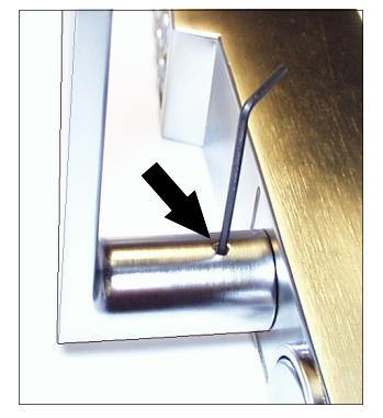
Fig. 3: Tighten lever set screw with 1/8" hex wrench
-
3a. Install the Adams Rite
®
product
as indicated by the Adams Rite® door prep guidelines and instructions.
- If a new installation, the face place must NOT be installed at this time.
- If a retrofit installation, remove the face plate.
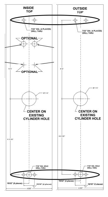
Fig. 4: Template (WI1459) through-bolt holes (circled)
Prepare the Door For "Through-Bolting"
- 4. Place template (WI1459) as shown. Important : Place the template on top of existing cylinder hole and parallel to the door edge.
-
4a. Drill
completely
through the door for through-bolting the four mounting holes and battery cover access bolt hole.
- IMPORTANT!--Drill the holes STRAIGHT THROUGH the door, or the through-bolts will not fit in the lock! THIS IS ESSENTIAL! Drill slowly and STRAIGHT through the door.
- Reposition the template as often as needed until it is placed correctly.
Insert the Interface Cylinder
5. Loosen the set screw, then remove the outside cylinder (if present--See Fig. 5).
Remove the Adams Right set screw, and replace with supplied "pointed" set screw. Re-tighten with supplied 7/64" Allen wrench.
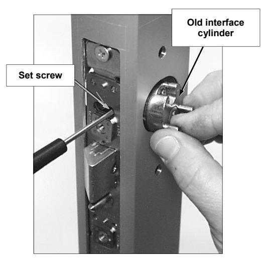
Fig. 5: Loosen set screw before removing the old interface cylinder (if present)
5a. Push in latch and hold latch in all the way.
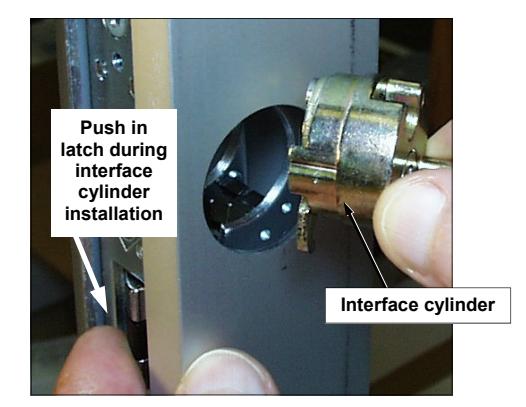
Fig. 5a: Push latch in and hold
5b. While holding in the latch , carefully insert the interface cylinder assembly into the cylinder hole. The hook must be in front of the latch retractor and pass through the notch in the lock case (see Fig. 5b).
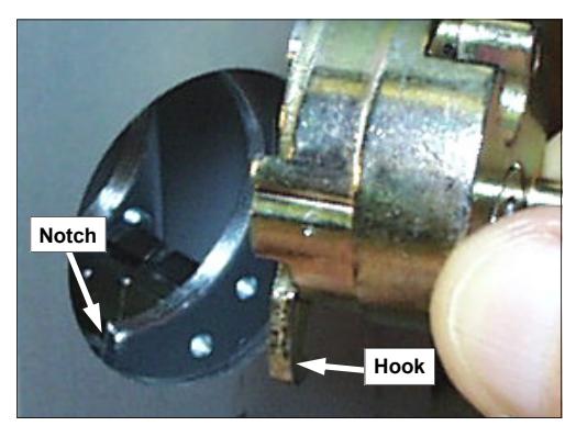
Fig. 5b: While holding latch in, place hook in front of the latch retractor and through the notch
5c. The interface cylinder must be centered and positioned flush with (or slightly below) the surface of the door (see Fig. 5c).
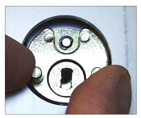
Fig. 5c: Position the interface cylinder
5d. With the interface cylinder HELD SECURELY in its correct position, tighten the set screw, securing the interface cylinder to the lock (see Fig. 5d).
Important! If the interface cylinder is not parallel to the door after tightening the set screw, then you must verify that the original Adams Rite<sup>®</sup> lock body was originally installed correctly (installed square to the door). Failure to ensure the interface cylinder is installed correctly could cause lock binding or improper operation of the lock mechanism.
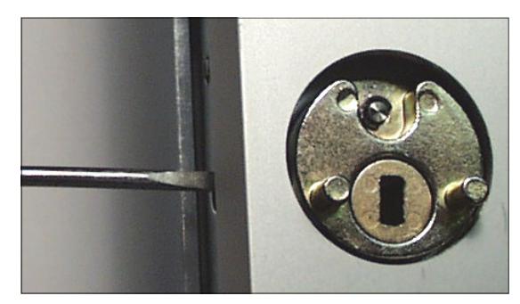
Fig. 5d: Tighten the interface cylinder set screw
5e. Install the latch face plate.
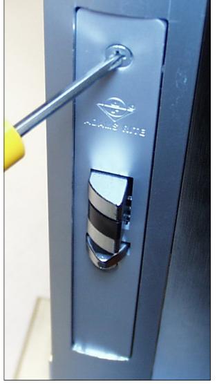
Fig. 5e: Install the latch face plate
5f. Verify the face of the interface cylinder ("HW1824") is positioned parallel to the surface of the door.
With a straight edge flush against the surface of the door as shown in the image below, place a small ruler on the right face of the interface cylinder to measure the distance between the face of the interface cylinder and the surface of the door (the right "gap"). See Fig. 5f below.
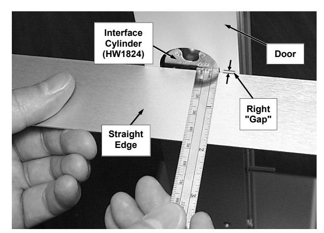
Fig. 5f: Measure right "gap": Place a small ruler against the <u>right</u> side of the interface cylinder.
5g. Measure the left "gap" with the ruler on the left face of the interface cylinder, as shown in Fig 5g, below:
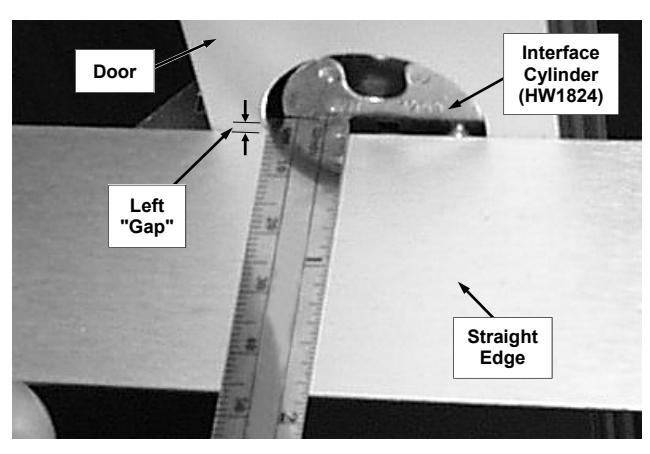
Fig. 5g: Measure left "gap": Place a small ruler against the <u>left</u> side of the interface cylinder.
The difference between the right and the left "gap" distances must not exceed 1/32" .
If face of the lock body is not parallel to the surface of the door and the difference between the left and right "gap" measurements exceeds 1/32", adjust the position of the Adams Rite <sup>®</sup> lock body until the face of the interface cylinder is parallel with the face of the door.
Install Lock
6. Install the DL lock onto the door by aligning the two posts on the front of the interface cylinder with the two corresponding holes in the back of the DL lock. Lift the tailpiece slightly to ensure the tailpiece enters the slot of the interface cylinder.
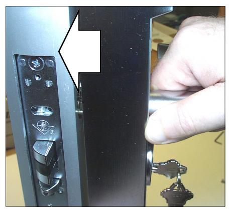
Fig. 6: Install lock onto the door
6a. Secure the DL lock to the door with four through-door mounting screws and two door plates. Place a door plate on top of a pair of mounting holes and loosely secure lock from the inside of the door. Snug all four mounting screws before final tightening. Do not over-tighten.
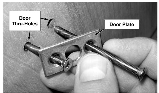
Fig. 6a: Secure lock to door -- loosely at first
Connect Batteries
7. Loosen the #8-32 Phillips pan head screw located on the rear side of the base plate at the bottom of the lock (see Fig. 7). Turn counter-clockwise until the battery cover slides off the housing. Do NOT remove the screw.
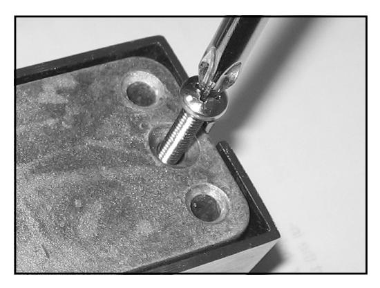
Fig. 7: The Phillips screw on the rear side locks or unlocks the battery cover. Do not remove screw .
7a. Plug in the battery connector and insert the battery pack into the battery compartment. Neatly push all wiring inside the compartment and on the side of the battery pack. Holding battery in place , slide cover back on. Secure the battery cover by tightening the #8-32 Phillips pan head screw located on the rear side of the base plate (access this screw from the 7/16" thru-hole drilled in the door). Do not over tighten the screw .
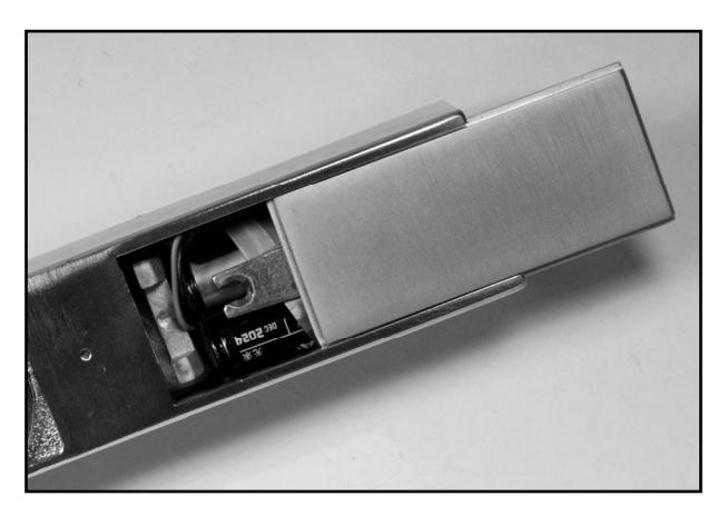
Fig. 7a: Install the battery pack: Push all wires inside the battery compartment and slide plate back on.
7b. Cover door plates with decorative plate covers by sliding them from top to bottom on door plates.
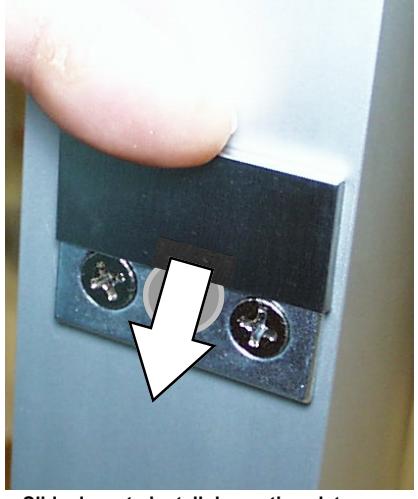
Fig. 7b: Slide down to install decorative plate covers
FOR NEW INSTALLATIONS: Refer to the programming manual (WI2258 or WI2264) for specific instructions for "First Time Startup" and "Change Factory Master Code" before connecting the battery.
The lock must be powered up as instructed (and have its factory Master Code changed) or erratic lock behavior can result.
Test operation : See next page.
TEST LOCK OPERATION
Before testing, be sure the lock has been powered-up using the specific instructions in the programming manual (for the PDL1300NW, use WI2258; for the DL1300NW, use WI2264).
1. With key removed, ensure that the lever can be pushed down and up. In addition, verify these lever motions DO NOT retract the latch.
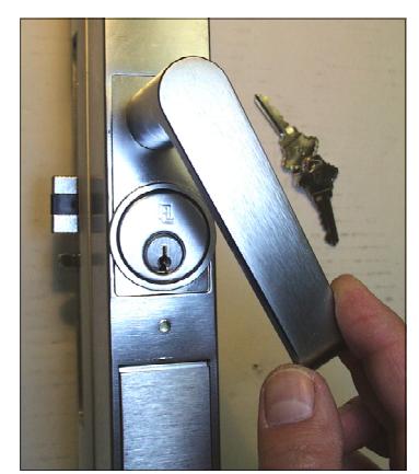
Test Step 1
2. Release lever. Insert key and turn key fully counterclockwise .
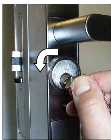
Test Step 2
3. Push the lever down and the latch should retract.
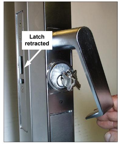
Test Step 3
4. Release lever. Turn key clockwise and remove key. The lever must not retract the latch when pressed down.
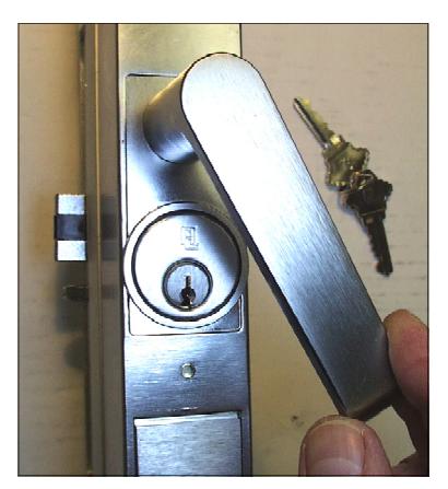
Test Step 4
-
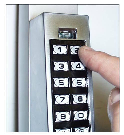
5. While pressing the default access code on the lock keypad (press "123456" on the DL/PDL1300NW), note the following:
- For each number key pressed, the red LED lights.
-
When the "6" button is pressed:
- 1. The green LED flashes for approximately 1 second.
- 2. The latch retracts when the lever is pushed down.
Test Step 5
6. Test the exit device mounted inside (paddle / egress bar, etc.) and confirm it is operating correctly.
For programming information, visit our Technical Library at http://tech.napcosecurity.com/ and download programming instructions for the PDL1300NW (WI2258) and DL1300NW (WI2264).
ALARM LOCK LIMITED WARRANTY
ALARM LOCK SYSTEMS, INC. (ALARM LOCK) warrants its products to be free from manufacturing defects in materials and workmanship for twenty four months following the date of manufacture. ALARM LOCK will, within said period, at its option, repair or replace any product failing to operate correctly without charge to the original purchaser or user.
This warranty shall not apply to any equipment, or any part thereof, which has been repaired by others, improperly installed, improperly used, abused, altered, damaged, subjected to acts of God, or on which any serial numbers have been altered, defaced or removed. Seller will not be responsible for any dismantling or reinstallation charges, environmental wear and tear, normal maintenance expenses, or shipping and freight expenses required to return products to ALARM LOCK. Additionally, this warranty shall not cover scratches, abrasions or deterioration due to the use of paints, solvents or other chemicals.
THERE ARE NO WARRANTIES, EXPRESS OR IM-PLIED, WHICH EXTEND BEYOND THE DESCRIPTION ON THE FACE HEREOF. THERE IS NO EXPRESS OR IMPLIED WARRANTY OF MERCHANTABILITY OR A WARRANTY OF FITNESS FOR A PARTICULAR PUR-POSE. ADDITIONALLY, THIS WARRANTY IS IN LIEU OF ALL OTHER OBLIGATIONS OR LIABILITIES ON THE PART OF ALARM LOCK.
Any action for breach of warranty, including but not limited to any implied warranty of merchantability, must be brought within the six months following the end of the warranty period.
IN NO CASE SHALL ALARM LOCK BE LIABLE TO ANY-ONE FOR ANY CONSEQUENTIAL OR INCIDENTAL DAMAGES FOR BREACH OF THIS OR ANY OTHER WARRANTY, EXPRESS OR IMPLIED, EVEN IF THE LOSS OR DAMAGE IS CAUSED BY THE SELLER'S OWN NEGLIGENCE OR FAULT.
In case of defect, contact the security professional who installed and maintains your security system. In order to exercise the warranty, the product must be returned by the security professional, shipping costs prepaid and insured to ALARM LOCK. After repair or replacement, ALARM LOCK assumes the cost of returning products under warranty. ALARM LOCK shall have no obligation under this warranty, or otherwise, if the product has been repaired by others, improperly installed, improperly used, abused, altered, damaged, subjected to accident, nuisance, flood, fire or acts of God, or on which any serial numbers have been altered, defaced or removed. ALARM LOCK will not be responsible for any dismantling, reassembly or reinstallation charges, environmental wear and tear, normal maintenance expenses, or shipping and freight expenses required to return products to ALARM LOCK. Additionally, this warranty shall not cover scratches, abrasions or deterioration due to the use of paints, solvents or other chemicals.
This warranty contains the entire warranty. It is the sole warranty and any prior agreements or representations, whether oral or written, are either merged herein or are expressly cancelled. ALARM LOCK neither assumes, nor authorizes any other person purporting to act on its behalf to modify, to change, or to assume for it, any other warranty or liability concerning its products.
In no event shall ALARM LOCK be liable for an amount in excess of ALARM LOCK's original selling price of the product, for any loss or damage, whether direct, indirect, incidental, consequential, or otherwise arising out of any failure of the product. Seller's warranty, as hereinabove set forth, shall not be enlarged, diminished or affected by and no obligation or liability shall arise or grow out of Seller's rendering of technical advice or service in connection with Buyer's order of the goods furnished hereunder.
ALARM LOCK RECOMMENDS THAT THE ENTIRE SYS-TEM BE COMPLETELY TESTED WEEKLY.
Warning: Despite frequent testing, and due to, but not limited to, any or all of the following; criminal tampering, electrical or communications disruption, it is possible for the system to fail to perform as expected. ALARM LOCK does not represent that the product/system may not be compromised or circumvented; or that the product or system will prevent any personal injury or property loss by burglary, robbery, fire or otherwise; nor that the product or system will in all cases provide adequate warning or protection. A properly installed and maintained alarm may only reduce risk of burglary, robbery, fire or otherwise but it is not insurance or a guarantee that these events will not occur. CONSEQUENTLY, SELLER SHALL HAVE NO LIA-BILITY FOR ANY PERSONAL INJURY, PROPERTY DAMAGE, OR OTHER LOSS BASED ON A CLAIM THE PRODUCT FAILED TO GIVE WARNING. Therefore, the installer should in turn advise the consumer to take any and all precautions for his or her safety including, but not limited to, fleeing the premises and calling police or fire department, in order to mitigate the possibilities of harm and/or damage.
ALARM LOCK is not an insurer of either the property or safety of the user's family or employees, and limits its liability for any loss or damage including incidental or consequential damages to ALARM LOCK's original selling price of the product regardless of the cause of such loss or damage.
Some states do not allow limitations on how long an implied warranty lasts or do not allow the exclusion or limitation of incidental or consequential damages, or differentiate in their treatment of limitations of liability for ordinary or gross negligence, so the above limitations or exclusions may not apply to you. This Warranty gives you specific legal rights and you may also have other rights which vary from state to state.