Alarm Lock 265 265L and 715 Installation and Operation Instructions
Open the original PDF document
View PDF
ELECTRONIC EXIT DOOR ALARMS PADDLE ARM MODEL 265/265L PUSH BAR MODEL 715 INSTALLATION AND OPERATION INSTRUCTIONS
P5708A 11/93
GENERAL DESCRIPTION
Models 265, 265L (long arm) and 715 are non-handed, delayed egress, electronic exit door locking systems. Arming is accomplished by actuating the deadbolt using a " rim cylinder (not included). When armed, depressing the paddle (Model 265) or push bar (Model 715) will release the deadbolt and sound an immediate alarm, however the deadlatch will prevent the door from opening until the 15-second exit delay has expired. Provisions are made for instant alarmed exit in the event of actual emergencies, such as smoke, fire, power failure, etc., using auxiliary detection equipment.
A standard 9V alkaline battery is provided. This battery must be installed at all times for proper operation of the unit. An LED on the Control Box indicates that the unit is armed.
SPECIFICATIONS
Power: 12Vac, 20VA Transformer; 9Vdc Alkaline Battery (Alarm Standby)
Current: 775mA max.; Alarm Circuit, Battery Only (Ac Failure): Standby, 20µA typ.; Alarm, 75mA typ.
Standby: 1 year typ.
Battery Life: 200 alarm sequences typ. or constant alarm for 7 hours typ.
Latch Release Time: 13-15 seconds
Auto Alarm Shutdown: 2 minutes typ. Sound Pressure Level: 95dB measured at 10 ft.
Operating Temperature: 20 to 135°F (-7 to 57°C) Finish: US28 Aluminum or US312 Duronodic Powder Coat Dimensions (hxwxd): Lock: Model 265, 8½"x18"x3½"; Model 715, 8½"x32"x3½"; Control Box: Model 265 or
Model 715, 8½"x33"x3¼"; Control Box: Model 265 or Model 715. 5"x3½"x2"
Shipping Weight: Model 265, 11½ lbs; Model 715, 13½ lbs.
FEATURES
- 15-second delayed egress
- Meets NFPA101 Life Safety Code
- Local smoke-detector input (easy key reset)
- Selectable alarm: continuous or two-minute shutdown
- Exterior key control (requires additional rim cylinder)
- · Audible low-battery indication
- Visual armed indicator LED (on Control Box)
- Piercing electronic siren (95dB at 10 feet)
- Full 1" throw deadbolt with rotating steel inserts.
EQUIPMENT SUPPLIED
- The following items are supplied with the product:
- Lock Assembly, with 9V alkaline backup battery
- Single-Door Keeper Assembly
- Paddle-Arm Assembly (Model 265); or Push Bar Assembly (Model 715)
- · Control Box Assembly
- Model 271 Flexible Conduit, with covers (2)
- Power Transformer
- 5-Conductor Cable (10 feet)
- Self-Adhesive Warning Labels (Model 265, 1; Model 715, 2) required to comply with NFPA 101 Hardware
OPTIONAL EQUIPMENT
- Available on special order: Option 88 Version Remote Interface and Alarm Indicator Relay
- Rim Cylinder, Model CER or equivalent (required)
- Surface Wiring Kit, Model SWK715
- Smoke Detector, 2-Wire. (Recommended: System Sensor 1400, 2400, 2400TH; or 1451, 2451, 2451TH with B401B Base)
INSTALLATION
Preliminary Considerations
Important! To comply with National Fire Protection Association Standard NFPA101, this lock must be connected to an approved supervised automatic fire-detection system or sprinkler system that will automatically unlatch the lock instantly in the event of an emergency. See Connection to Remote Life-Safety Equipment.
Models 265 and 715 are designed for use on doors equipped with door checks to ensure that the door closes completely and automatically. The Lock Assembly is mounted on a single left- or right-handed reverse steel door. (These instructions include information for mounting Model 715 onto a narrow-stile glass door). Mounting onto a solid door
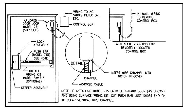
Fig. 1 Typical Installation, left-handed reverse door, inside view. If snaking wires within door, see Note above.
requires an optional Surface Wiring Kit, Model SWK715, for routing of wires from the Lock Assembly to the Control Box. Note: If mounting onto a hollow door, wiring may be routed inside the door. A <sup>3</sup>/<sub>8</sub>x36" straight drill will be required to drill through the door frame from the top and hinged-side edges and through internal reinforcements to allow snaking of wires. In this case, drill wire exit and entry holes and snake wires before mounting the Lock Assembly.
Sufficient cable (10 feet) is supplied to permit mounting of the Control Box on the hinged side of the door, on the wall adjacent to the door frame. If mounting further away (above a dropped ceiling, for example), a longer cable will be required.
Lock Assembly & Keeper Assembly (See Note, Page 1)
The printed mounting template supplied is for a left-handed reverse door. (For installation onto a right-handed reverse door, turn template upside down.) Fold the template up 90° on the dashed line as indicated. With the door closed, tape the template to the inside surface of the door and jamb so that the hole for the rim cylinder is about 38" above the floor, and proceed as follows. (Note special instructions for mounting Model 715 onto a narrow-stile glass door.)
Precautions:
- Do not connect the 9-volt battery or ac power until the installation is complete.
- The round ferrite magnet and the glass-encapsulated reed switch on the Lock Assembly circuit board are fragile. Exercise care while the Lock Cover is removed.
- Avoid getting grease on Solenoid Plunger or the inner surface of the Solenoid Backplate.
- When making electrical connections to the Lock Assembly, be sure that the wires do not interfere with the operation of the Solenoid Backplate.
If the sounder cable is removed from the Lock Assembly circuit board, observe polarity shown on the label when installing.
1. Mark and drill the following holes:
-
a. six mounting holes, four* for the Lock Assembly and two (of the three shown) for the Keeper Assembly;
- *Note: For mounting Model 715 onto a narrow-stile glass door, drill only two holes for the Lock Assembly, along the jamb edge.
-
b. one <sup>3</sup>/<sub>8</sub>" cable entry hole* (aligns with hole in baseplate, near terminal strip);
- Note: Not for glass doors.
- c. (only if an exterior cylinder is used), one 11/4" diameter hole.
- 2. Remove the Lock Cover. With the door ajar, operate the Cam Latch to its latched position. Remove the four #6 screws that secure the cover to the base, two on each side. Pull the cover up about an inch, then fold it over toward the Cam Latch to remove. (Reverse the foregoing procedure to replace the Lock Cover.) Note: Exercise caution whenever the Lock Cover is removed.
- 3. Install the interior rim cylinder. Detach two Springs and the four screws holding the Rim Cylinder Housing to the
Bolt Cover. Cut the rim cylinder tailpiece so that it extends " beyond the Rim Cylinder Housing. Facing the front of the lock, install the rim cylinder with the keyway horizontal. Secure the cylinder to the Rim Cylinder Housing using the screws supplied with the cylinder. Guiding the cylinder's tailpiece into the interior crosshole, replace the Rim Cylinder Housing onto the Bolt Cover using the four screws. Reattach the two Springs.
- 4. Test the deadbolt. Check for proper operation using the key. The key should be removable from the lock in either the fully locked or the fully unlocked position. If it is not, the cylinder and the crosshole are misaligned. Remove the Rim Cylinder Housing, rotate the crosshole turn clockwise, then reinstall the Rim Cylinder Housing. (Note: The deadbolt can be projected into the Keeper Assembly by turning the key counterclockwise one full turn.)
- 5. (For exterior cylinder only.) Install the Rim Cylinder from the outside with the keyway horizontal. Mount with the supplied screws. Cut the tailpiece so that it extends <sup>3</sup>/<sub>8</sub>" beyond the inside surface of the door. Guide the tailpiece into the exterior crosshole. Test the deadbolt as described in Step 4 above.
- 6. Mount the lock*. Install the lock onto the door using four #10 screws (supplied). For maximum holding strength, the Lock Assembly should be through-bolted using at least #10 carriage bolts. If installing Model 715, do not tighten at this time.
*Note: If installing Model 715 onto a narrow-stile glass door, attach the Channel and Push Bar (see Step 7b) before mounting onto the door and secure the Channel to the Channel Retainer Bracket using two #10-24 screws from the rear.
-
7a. (For Model 265 only.) The Paddle Arm is factory mounted for use on a left-handed reverse door. If the lock is installed on a right-handed reverse door, remove the two screws that secure the paddle to the arm and remount the paddle upside down.
- b. (For Model 715 only.) Insert the Push Bar and Channel Assembly under the Channel Retainer Bracket, which is mounted on the Lock Baseplate. Hold the Push Bar and Channel Assembly horizontally against the door using a level. Slide the End Cap Retaining Bracket into the end of the Channel. After checking that the bar is level, use the Channel as a template to mark and drill two #22 or " mounting holes into the door. If the Channel is too long, cut the Channel and the Channel Insert to the proper length, keeping them as long as possible, and deburr the edges. Note: If installing onto a left-hand door and using a Surface Wiring Kit, cut the Channel and Channel Insert just enough to clear the vertical wire channel. See Fig. 1.
Mount the End Cap Retaining Bracket to the door with two #10 screws provided, then tighten the lock securely to the door. Remove the #10-32x½" Phillips screw and lock
washer from the Paddle Arm Hinge Bracket. Depress the Paddle Arm Hinge Bracket slightly and attach the Push Bar to the bracket using the #10-32 Phillips screw and lock washer just removed. Attach the End Cap to the Retaining Bracket using the #10-24x½" oval-head Phillips screw supplied.
- 8. Install the Keeper Assembly. Orient the Keeper Assembly against the door jamb so that the Cam Latch and the deadbolt on the lock are aligned with the respective holes in the Keeper Cover. Remove the Keeper Cover and install the Keeper Base onto the door jamb with two flat-head screws (supplied) until screws are snug, but not tight. Insert the Keeper Roller Pin into the ¼ hole at the latch end of the Keeper. Pass the Keeper Roller Pin through the Keeper Roller and into the second hole. Install the #6-32 x ½ Phillips-head (or optional tamper-proof) retaining screw into the small hole at the latch end to secure the Keeper Roller Pin. (Note: If the fit is tight, it may be necessary to tap the pin into the holes using a mallet.)
- 9. Adjust the Keeper Assembly. Close the door, project the deadbolt and adjust the Keeper Assembly so that the door is tightly latched. Retract the deadbolt then, holding the Keeper Assembly in place, release the latch and open the door. Remove the Keeper Roller Pin and Roller (a tightly-fitting pin may be driven out through the <sup>1</sup>/<sub>8</sub>" access hole accessible at the deadbolt hole), then fully tighten the two flat-head screws securing the Keeper Base. Replace the Keeper Roller Pin and Roller. Replace the Keeper Cover and and the Lock Cover (Cam Latch must be in "thrown" position) and check operation of the lock. If necessary, repeat this step until proper operation is achieved. Remove the Lock Cover once again.
- 10. Lock the Keeper Assembly. When proper operation is confirmed, mark and drill the hole for the third Keeper Base Screw and install the remaining flat-head screw to lock the Keeper Assembly in place.
Control Box
The Control Box is mounted on the hinged side of the door, generally on the wall adjacent to the door frame, but it may be extended to a hidden remote location if its visual LED indication is not required.
- 1. Remove the Control Box cover.
- Select a location for the Control Box on the hinged side of the door so that the LED is clearly visible. Mount the Control Box onto the door frame or adjacent wall using the three #10x<sup>3</sup>/<sub>4</sub>" self-tapping screws provided.
WIRING
Wiring from the Lock Assembly to the Control Box is concealed within the door, exiting at the hinged side. A protective Flexible Conduit loop (Model 271) transfers the 5-conductor cable from the door to the Control Box. Note: All holes drilled into the door for the passage of wires should be deburred to prevent sharp edges from cutting into the insulation.
- 1. Insert the loose end of the Flexible Conduit into the <sup>a</sup> hole in the Control Box and secure it with the retaining clip.
- Mount the box end of the Flexible Conduit to the door using the two #10x¾" screws provided. Be sure to leave enough of a loop in the conduit for the door to open fully. Drill a hole through the conduit bracket and into the door.
- 3. Referring to the Wiring Diagram, connect one end of the 5-conductor cable to the Control-Box Terminal Strip TS2.
- 4. Run the cable through the Flexible Conduit, through the door, and out through the <sup>3</sup>/<sub>8</sub>" wire-entry hole under the baseplate of the lock.
- Connect one end of a UL-listed two-conductor #18AWG cable (not supplied) to the Control-Box Terminal Strip TS1, Terminals 1 and 2. Connect the other end to the 12Vac Power Transformer supplied.
- 6. Install the Control-Box cover.
Connection to Remote Life-Safety Equipment
National Fire Protection Association Standard NFPA101 requires that this lock be connected to an approved supervised automatic fire-detection system or sprinkler system that will automatically unlatch the lock instantly in the event of an emergency.
1. To utilize a smoke detector to unlatch the lock instantly in the event of a fire emergency, remove the factory-installed 1200W end-of-line resistor (5%, ½-watt; color code, brown/red/red/gold) from the Control-Box Terminal Strip TS1, Terminals 3 and 4; do not discard the resistor. Connect one end of a UL-listed two-conductor cable, #22AWG minimum, to the terminal strip (Terminals 3 and 4). Observing polarity indicated on the Wiring Diagram, connect the other end of the cable to a 2-wire smoke detector (see OPTIONAL EQUIPMENT: Recommended Smoke Detectors) and install the end-of-line resistor
| Wire Size (AWG) | Maximum Cable Length |
|---|---|
| #18 | 500 feet |
| #20 | 350 feet |
| #22 | 250 feet |
directly across the smoke-detector's terminals. (The endof-line resistor is not polarized.) Refer to the following table for maximum cable length allowed between control box and smoke detector.
2. To utilize a UL-listed supervised automatic fire detection system, a normally-closed remote keyswitch or other normally-closed device to unlatch the lock instantly in the event of a fire (or other) emergency, connect one end of a UL-listed two-conductor #22AWG cable to the Control-Box Terminal Strip TS1, Terminals 5 and 6 and remove the factory-installed jumper. Connect the other end of the cable to a normally-closed fire-detection system, keyswitch, or other normally-closed device. (If Terminals 5 and 6 are not used, the jumper must remain in place.) Important! If connecting multiple locks to a normally-closed device, do not intermix Terminals 5 and 6 between units; that is, Terminal 5 of all units must be connected
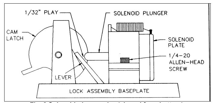
Fig. 2 Solenoid-plunger play (viewed from bottom).
together and Terminal 6 of all units must be connected together. Be sure to check that all doors unlock when the fire-panel relay opens.
COMPLETING THE INSTALLATION
- The Lock Assembly is factory wired to provide a continuous alarm when tripped until reset by disarming. For an automatic alarm shutdown after two minutes, remove the Shutdown Jumper (see Wiring Diagram).
- 2. Connect the battery clip to the 9-volt battery.
- 3. Replace the Lock Cover, being sure that the Cam Latch is first set to its "thrown" (latched) position.
- Connect the Power Transformer to a continuous source of 110-120Vac power. Do not connect to a switched outlet.
- 5. Reset the unit by arming and disarming (projecting and withdrawing the deadbolt). Note: A loud beep will sound
momentarily when disarming. The LED on the control box will light when armed.
Solenoid Position Adjustment
A fine adjustment of the Solenoid may be required if its factory position has been disturbed. To check the position of the solenoid, apply power to the lock. With the Solenoid energized, check for approximately " play as shown in Fig. 2. If adjustment is indicated, loosen the 0 Allenhead screw. Pull open the Cam Latch slightly and slide the Solenoid toward the latch until there is " clearance be tween the Lever and the Cam Latch, then tighten the Allen-head screw.
FUNCTIONAL TEST
Be sure that the 9-volt backup battery is connected and the Power Transformer is plugged in. Final testing should be made with all covers in place.
1. Close the door and arm the lock by projecting the deadbolt. Test the exit delay by pressing the bar (Model 715) or paddle (Model 265). The alarm will sound instantly and the deadbolt will retract, however the Cam Latch will be energized for the duration of the selected exit delay, preventing the door from being opened. Confirm that the door may be opened after the exit delay has elapsed and that the lock relatches after 5 seconds. Reset the lock by disarming (withdrawing the deadbolt).
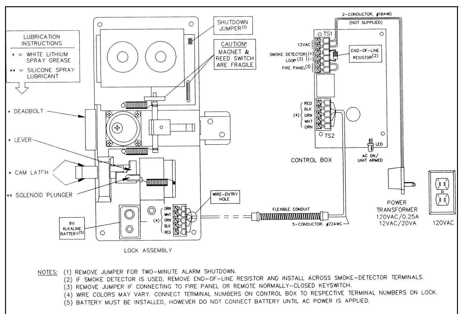
Fig. 3 Wiring Diagram, Models 265 & 715.
EXPLODED VIEW AND PARTS LIST, MODEL 265
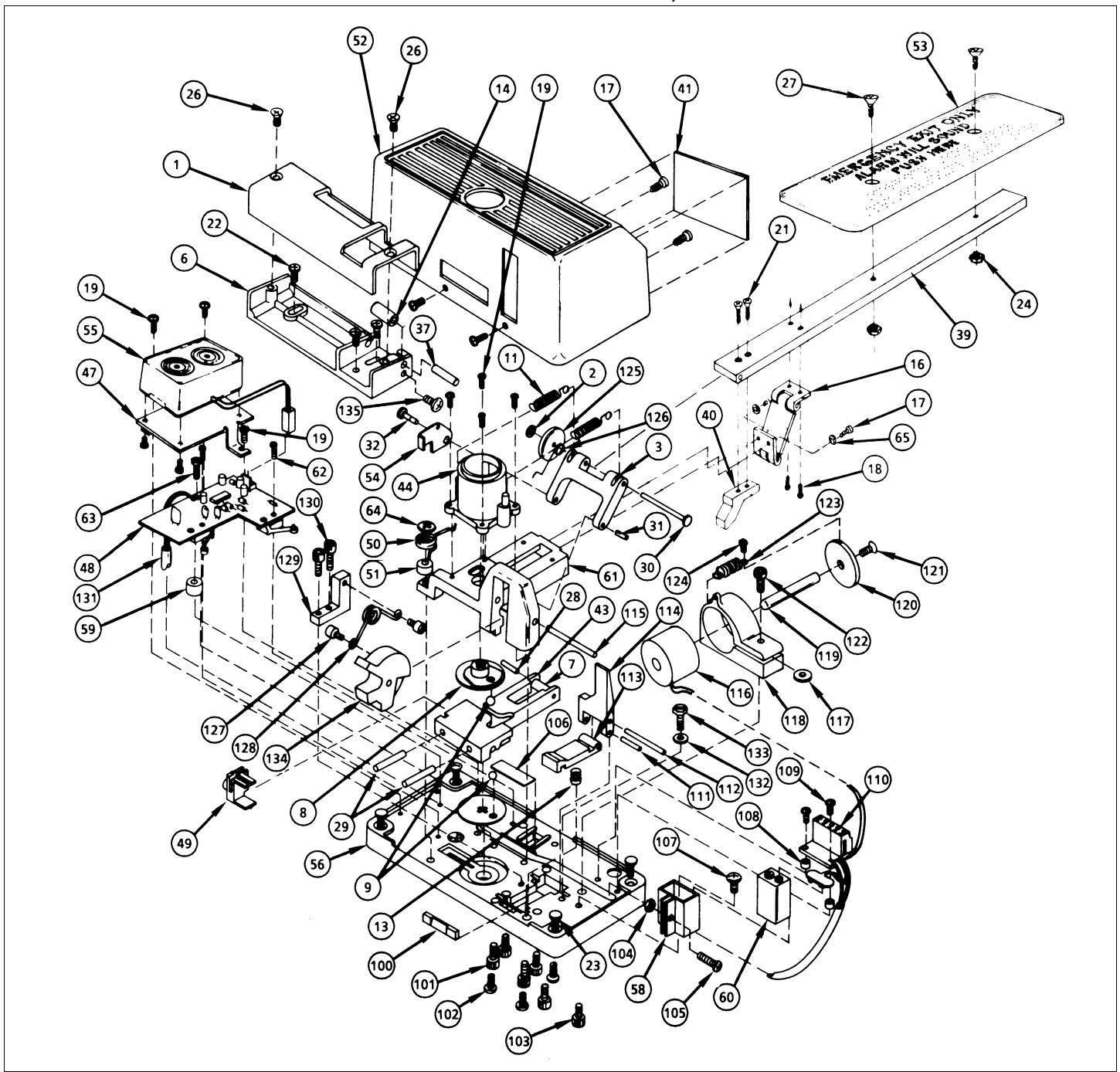
- 2. When the lock is disarmed, pressing the bar or paddle will open the door instantly without sounding the alarm. Check that the lock relatches after 5 seconds.
- 3. Trip the fire-detection or other emergency device with the lock armed. Press the bar or paddle and check that the latch is released instantly and that the alarm sounds. The smoke detector is reset by disarming the lock.
- 4. The unit is electrically failsafe. Should any wire open for any reason, the exit delay will be eliminated and the door may be exited by pressing the bar or paddle.
Low-Battery Indication
A low-battery condition will be indicated by a "chirp" from the sounder about once each minute. Be sure to replace
the battery promptly. An alkaline replacement is strongly recommended for optimum reliability and length of service.
Lubrication
These models are designed to provide many years of reliable service when lubricated periodically. Inspect the lock on a routine basis in accordance with anticipated use. Replenish the factory-applied lubricants at least every five years or 25,000 operations, whichever occurs first, using the specified lubricants at the points shown in the Wiring Diagram.
| Ref. No. | Description | Part No. |
| 1 | Keeper Cover | P0248 |
| 2 | Retaining Ring, Truarc | P1140 |
| 3 | Pivot Arm | P5093 |
| 6 | Keeper Base | P5642 |
| 7 | Roller, Deadbolt | P1158 |
| 8 | Cam, Plastic | P1159 |
| 9 | Ball Bearing | P1160 |
| 11 | Spring, Return | P1168 |
| 13 | Spring, Dropout Lever | P5635 |
| 14 | Keeper Roller | P5643 |
| 16 | Hinge | P1260 |
| 17 | Screw, 6-32x Phillips Truss | P1508 |
| 18 | Screw, 6-32x FH Phillips | P5555 |
| 19 | Screw, 6-32x PH Phillips | P1520 |
| 21 | Screw, 8-32x FH Phillips | P4198 |
| 22 | Screw, #10x1 FH Phillips | P1676 |
| 23 | Screw, #10x1 PH Phillips | P1675 |
| 24 | Nut, 10-32x | P1684 |
| 26 | Screw, 10-32x FH Phillips | P1740 |
| 27 | Screw, #10x1 OH Phillips | P1748 |
| 28 | Pin, x1.085 | P1927 |
| 29 | Pin, x1 Hardened | P1928 |
| 30 | Hinge Pin | P5679 |
| 31 | Pin, x | P1930 |
| 32 | Pin, x | P1931 |
| 37 | Pin, Keeper Roller | P5644 |
| 39 | Paddle Arm | P4493 |
| 40 | Trigger Cam | P4495 |
| 41 | Label, UL | P5323 |
| 43 | Deadlock Bolt | P1143 |
| 44 | Cylinder Housing | P1145 |
| 47 | Mounting Plate, Sounder | P5012 |
| 48 | Lock Assembly PCB | S5909 |
| 49 | Cam Follower | P5019 |
| 50 | Tension Spring | P5029 |
| 51 | Tension Spring Spacer | P5030 |
| 52 | Lock Cover | P5014 |
| 53 | Paddle Plate | P5050 |
| 54 | Deadlock | P5054 |
| 55 | Sounder Subassembly | S5228 |
| 56 | Baseplate | P5631 |
| 58 | Battery Bracket | P5098 |
| 59 | Spacer | P5089 |
| 60 | Battery, 9-Volt | P5103 |
| 61 | Bolt Cover | P5633 |
| 62 | Screw, 2-56x PH Phillips | P5195 |
| 63 | Screw, 4-40x PH Phillips | P5194 |
| 64 | Screw, 10-24x Hex Slot | P5197 |
| 65 | Lock Washer, #6 | P5244 |
| 100 | Bar, Dropout | P5650 |
| 101 | Screw, 10-24x1 Allen Flat | P5712 |
| 102 | Screw, 10-24x PH Phillips ST | P4155 |
| Ref. No. | Description | Part No. |
|---|---|---|
| 103 | Screw, 10-32x Allen | P5191 |
| 104 | Nut, 4-40x | P1416 |
| 105 | Screw, 4-40x PH Phillips | P5194 |
| 106 | Insulator, Fish Paper | P5651 |
| 107 | Screw, 8-32x0.375 PH Phillips | P5714 |
| 108 | Spacer | P5089 |
| 109 | Screw, 4-40x PH Phillips | P5194 |
| 110 | Terminal Board | S5909 |
| 111 | Shaft, Dropout Lever | P5639 |
| 112 | Shaft, Lever | P5649 |
| 113 | Lever, Dropout | P5636 |
| 114 | Lever | P5637 |
| 115 | Shaft, Latch | P5634 |
| 116 | Electromagnet | P5680 |
| 117 | Washer, xx0.060 | P5396 |
| 118 | Clamp | P5079 |
| 119 | Plunger, Solenoid | P5647 |
| 120 | Backstop, Solenoid | P5646 |
| 121 | Screw, Backstop | P5670 |
| 122 | Screw, -20x0.625 Allen Cap | P5716 |
| 123 | Spring, Solenoid Return | P5645 |
| 124 | Screw, 4-40x PH Phillips | P5194 |
| 125 | Magnet, Disc | P5707 |
| 126 | Spring, Deadlock | P5628 |
| 127 | Screw, Latch Spring | P5669 |
| 128 | Spring, Latch | P5638 |
| 129 | Spring Holder | P5640 |
| 130 | Screw, 6-32x0.625 Allen Cap | P5710 |
| 131 | Wire, 6-Conductor | P5748 |
| 132 | Washer, #6x0.437 OD | P5715 |
| 133 | Screw, 6-32x0.375 Hex Slot | P5713 |
| 134 | Latch | P5632 |
| 135 | Screw, 6-32x, Phillips Truss | P1508 |
SUBASSEMBLIES
The following subassemblies are supplied complete and assembled only, comprising the reference numbers shown.
| Control Box PCB (not shown) S5912 | |
|---|---|
| Lever Subassembly (Ref. Nos. 111, 112, 113, 114) S5910 | |
| Deadbolt Subassembly (Ref. Nos. 7, 28, 29, 43) S5907 |
| Bolt Cover/Paddle Arm Subassembly (Ref. Nos. 2, 3, 11, 18, 19, 21, |
|---|
| 24, 27, 30, 31, 32, 39, 40, 44, 53, 54, 65, 115, 125, 126, 134, |
| 135) S5911 |
EXPLODED VIEW AND PARTS LIST, MODEL 715
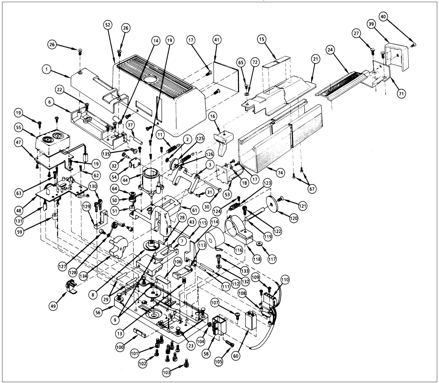
| Ref. No. | Description | Part No. |
|---|---|---|
| 1 | Keeper Cover | P0248 |
| 2 | Retaining Ring, Truarc | P1140 |
| 3 | Pivot Arm | P5093 |
| 6 | Keeper Base | P5642 |
| 7 | Roller, Deadbolt | P1158 |
| 8 | Cam, Plastic | P1159 |
| 9 | Ball Bearing | P1160 |
| 11 | Spring, Return | P1168 |
| 13 | Spring, Dropout Lever | P5635 |
| 14 | Keeper Roller | P5643 |
| 15 | Label, Push Bar | P5023 |
| 16 | Hinge Bracket | P5022 |
| 17 | Screw, 6-32x, Phillips Truss | P1508 |
| 18 | Lock Washer, #6 | P5244 |
| 19 | Screw, 6-32x PH Phillips | P1520 |
| Ref. No. | Description | Part No. |
|---|---|---|
| 21 | Push Bar | P5010 |
| 22 | Screw, #10x1 FH Phillips | P1676 |
| 23 | Screw, #10x1 PH Phillips | P1675 |
| 24 | Channel Insert | P5046 |
| 26 | Screw, 10-32x FH Phillips | P1740 |
| 27 | Screw, #10x1 PH Phillips | P1675 |
| 28 | Pin, x1.085 | P1927 |
| 29 | Pin, x1 Hardened | P1928 |
| 30 | Hinge Pin | P5679 |
| 31 | Pin, x | P1930 |
| 32 | Pin, x | P1931 |
| 37 | Pin, Keeper Roller | P5644 |
| 39 | End Cap | P5034 |
| 40 | Screw, 10-24x Oval Phillips | P5202 |
| 41 | Label, UL | P5234 |
| Ref. No. | Description | Part No. |
|---|---|---|
| 43 | Deadlock Bolt | P1143 |
| 44 | Cylinder Housing | P1145 |
| 47 | Mounting Plate, Sounder | P5012 |
| 48 | Lock Assembly PCB | S5909 |
| 49 | Cam Follower | P5019 |
| 50 | Tension Spring | P5029 |
| 51 | Tension Spring Spacer | P5030 |
| 52 | Lock Cover | P5014 |
| 53 | Retaining Bracket | P5017 |
| 54 | Deadlock | P5054 |
| 55 | Sounder Subassembly | S5228 |
| 56 | Baseplate | P5631 |
| 58 | Battery Bracket | P5098 |
| 59 | Spacer | P5089 |
| 60 | Battery, 9-Volt | P5103 |
| 61 | Bolt Cover | P5633 |
| 62 | Screw, 2-56x PH Phillips | P5195 |
| 63 | Screw, 4-40x PH Phillips | P5194 |
| 64 | Screw, 10-24x Hex Slot | P5197 |
| 65 | Screw, 10-32x PH Phillips | P5200 |
| 67 | Screw, 10-32x FH Phillips | P1735 |
| 71 | Retaining Bracket | P5045 |
| 72 | Lock Washer, #10 | P5201 |
| 74 | Base Channel | P5011 |
| 100 | Bar, Dropout | P5650 |
| 101 | Screw, 10-24x1 Allen Flat | P5712 |
| 102 | Screw, 10-24x PH Phillips ST | P4155 |
| 103 | Screw, 10-32x Allen | P5191 |
| 104 | Nut, 4-40x | P1416 |
| 105 | Screw, 4-40x PH Phillips | P5194 |
| Ref. No. | Description | Part No. |
|---|---|---|
| 106 | Insulator, Fish Paper | P5651 |
| 107 | Screw, 8-32x0.375 PH Phillips | P5714 |
| 108 | Spacer | P5089 |
| 109 | Screw, 4-40x PH Phillips | P5194 |
| 110 | Terminal Board | S5909 |
| 111 | Shaft, Dropout Lever | P5639 |
| 112 | Shaft, Lever | P5649 |
| 113 | Lever, Dropout | P5636 |
| 114 | Lever | P5637 |
| 115 | Shaft, Latch | P5634 |
| 116 | Electromagnet | P5680 |
| 117 | Washer, xx0.060 | P5396 |
| 118 | Clamp | P5079 |
| 119 | Plunger, Solenoid | P5647 |
| 120 | Backstop, Solenoid | P5646 |
| 121 | Screw, Backstop | P5670 |
| 122 | Screw, -20x0.625 Allen Cap | P5716 |
| 123 | Spring, Solenoid Return | P5645 |
| 124 | Screw, 4-40x PH Phillips | P5194 |
| 125 | Magnet, Disc | P5707 |
| 126 | Spring, Deadlock | P5628 |
| 127 | Screw, Latch Spring | P5669 |
| 128 | Spring, Latch | P5638 |
| 129 | Spring Holder | P5640 |
| 130 | Screw, 6-32x0.625 Allen Cap | P5710 |
| 131 | Wire, 6-Conductor | P5748 |
| 132 | Washer, #6x0.437 OD | P5715 |
| 133 | Screw, 6-32x0.375 Hex Slot | P5713 |
| 134 | Latch | P5632 |
| 135 | Screw, 6-32x, Phillips Truss | P1508 |
SUBASSEMBLIES
The following subassemblies are supplied complete and assembled only, comprising the reference numbers shown.
| Control Box PCB (not shown)S5912 | |
|---|---|
| Lever Subassembly (Ref. Nos. 111, 112, 113, 114)S5910 | |
| Deadbolt Subassembly (Ref. Nos. 7, 28, 29, 43)S5907 |
Bolt Cover Subassembly (Ref. Nos. 2, 3, 11, 16, 17, 18, 19, 30, 31, 32, 44, 53, 54, 115, 125, 126, 134) ...................... S5908
Alarm Lock Systems, Inc. 345 Bayview Avenue, Amityville, New York 11701 Call Toll Free: 800-ALA-LOCK (800-252-5625)