Alarm Controls Flush Mount Vandal Resistant Weatherproof Digital Keypad Model KP-200 Insrtuctions
Open the original PDF document
View PDFMODEL KP-200 FLUSH MOUNT VANDAL RESISTANT WEATHERPROOF DIGITAL KEYPAD
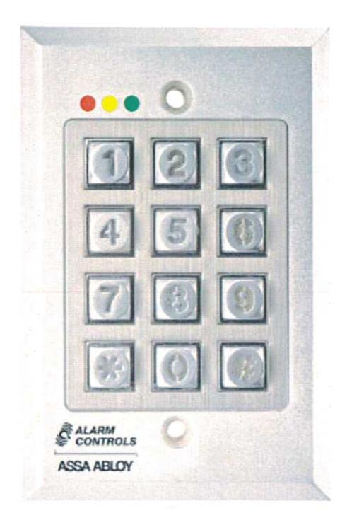
Model KP-200 is a self-contained vandal resistant digital keypad. This dual-relay output keypad is suitable for residential, industrial, and commercial installations. It is compatible with all electric locking devices. Durable backlit metal keys and a rugged metal housing protect the keypad from harsh environments.

Alarm Controls 10027 S. 51st Street Suite 102 Phoenix, AZ 85044 (800) 645-5538
ASSA ABLOY, the global leader in door opening solutions
INSTALLATION
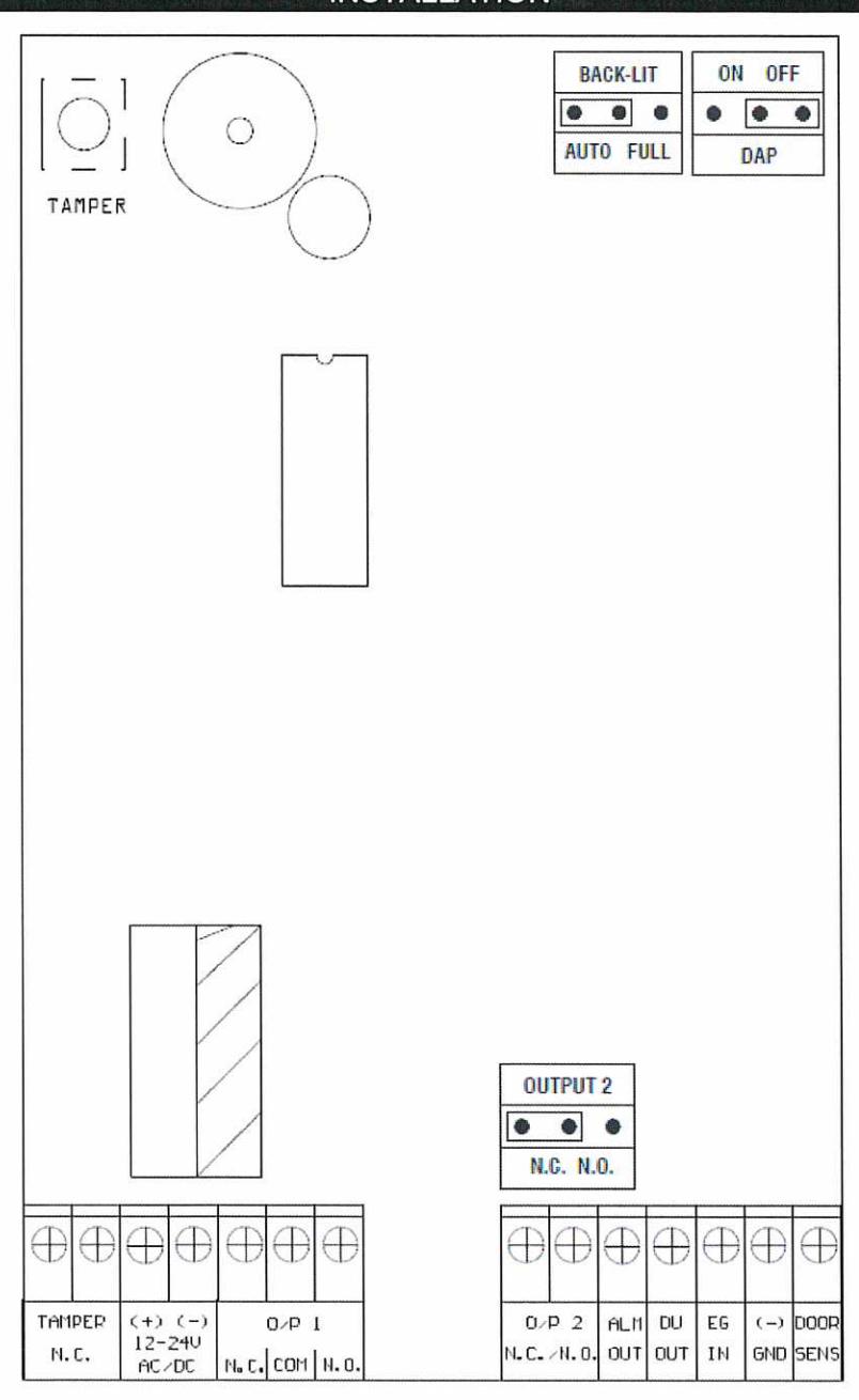
- 1. Remove tamper proof screws from the front of the keypad with the provided tool.
- 2. Make all required wiring connections to the terminal blocks.
- 3. Place the keypad faceplate on the back box and secure with the tamper proof screws.
| WIRING | ||
|---|---|---|
|
Power Input
(12-24V AC/DC) |
12 or 24 AC or DC. AC power can be connected without observing polarity requirement. Connect DC power with polarity as indicated. | |
| Output 1 | SPDT dry 1 Amp contact. Output can be programmed for latching or momentary operation. | |
| Output 2 | Form C relay with 1 Amp rating. Jumper selectable N.C. (Normally Closed) or N.O. (Normally Open) contacts. | |
|
Egress Input
(EG IN) |
A normally-open request to exit station can be connected to this terminal and ground (-). Connecting the terminal to ground will operate output 1 in the same manner as a valid user code. | |
|
Duress Output
(DU OUT) |
NPN transistor open collector output that switches to ground (-) after the duress code has been entered. Output rating Ic max: 100mA sink, Vc max: 24VDC. | |
|
Ground (-)
(GND) |
System ground (-). | |
|
Door Position Sensor
Input (DOOR SENS) |
A normally-closed contact connected to this terminal and ground (-) will provide a door position monitor. This terminal must be connected to ground (-) if not used. The factory installed jumper must be removed if using this input. | |
|
Alarm Output
(ALM OUT) |
NPN transistor open collector output that switches to ground (-) when door position sensor shows an open door, but a valid code was not entered. Used to trigger an external alarm or notify an access control system. | |
|
Normally-closed
Tamper (Tamper N/C) |
Normally-closed output pair activated by the tamper switch if the keypad faceplate is removed from the back box. | |
KEYPAD INITIATION
Keypad initiation must be done at the initial turn-on of the keypad.
- 1. Connect power to the keypad.
- 2. Put the keypad in Program Mode by entering " 0 0 0 0 * ". The keypad will beep twice and the yellow LED will be on and not blinking. Proceed to Entering a new installer code.
- 3. The keypad will beep twice and the keypad initiation is complete.
- 4. Enter "*" to exit Program Mode. The yellow LED will begin blinking.
ENTERING A NEW INSTALLER CODE
It is strongly recommended that the Installer Code be changed from the default " 0 0 0 0 ". If the Installer Code is not known, please refer to the section on Direct Access to Programming .
- 1. Put the keypad in Program Mode by entering " 0 0 0 0 * " or the current installer code. The keypad will beep twice and the yellow LED will be on and not blinking.
- 2. Enter "0 (4 to 8 digit new installer code) #". For example, to change the Installer Code to 1 2 3 4 you would enter "0 1 2 3 4 #".
- 3. The keypad will beep twice indicating that the new Installer Code has been accepted.
- 4. Enter "*" to exit Program Mode. The yellow LED will begin blinking.
PROGRAMMING MODE
It is necessary to put the keypad in Programming Mode in order to access all keypad configuration settings.
- Put the keypad in Program Mode by entering the Installer Code followed by the "*". The keypad will beep twice and the yellow LED will be on and not blinking.
- 2. Enter "*" to exit Program Mode. The yellow LED will begin blinking.
PROGRAMMING USER CODES
User Codes are 4 to 8 digits long and must not be the same as the Installer Code. A User Code can be assigned to operate either Output 1 or Output 2. The keypad can store up to 100 User Codes for Output 1 and up to 10 User Codes for Output 2.
Each User Code has a Code Number . Output 1 Code Numbers are two digits ranging from " 00 " to " 99 ". Output 2 Code Numbers are one digit ranging from " 0 " to " 9 ".
- Put the keypad in Program Mode by entering the Installer Code followed by the "*". The keypad will beep twice and the yellow LED will be on and not blinking.
-
2. Enter "(Output) (Code Number) (User Code) #".
- For example, if you wish to assign a User Code of "6 7 8 9" to Code Number "00" to operate Output 1 you would enter "1 0 0 6 7 8 9 #".
- If you wish to assign a User Code of "3 4 3 3" to Code Number "1" to operate Output 2 you would enter "2 1 3 4 3 3 #".
- 3. Enter "*" to exit Program Mode. The yellow LED will begin blinking.
OPERATION
Enter a valid User Code to activate the associated Output. The keypad must be in standby mode (yellow LED blinking).
1. Enter "(User Code) #".
For example, if the User Code is "1234" you would enter "1 2 3 4 #".
DELETING USER CODES
- Put the keypad in Program Mode by entering the Installer Code followed by the "*". The keypad will beep twice and the yellow LED will be on and not blinking.
- 2. Enter "(Output) (Code Number) #".
For example, if you wish to delete the User Code in Code Number "02" for Output 1 you would enter "1 0 2 #".
If you wish to delete the User Code in Code Number "3" for Output 2 you would enter "2 3 #".
To delete all User Codes enter "8 9 0 1 #".
3. Enter "*" to exit Program Mode. The yellow LED will begin blinking.
FALSE CODE LOCKOUT
The keypad can be programmed to be disabled for 15 minutes after 5 successive false code entries.
- Put the keypad in Program Mode by entering the Installer Code followed by the "*". The keypad will beep twice and the yellow LED will be on and not blinking.
- 2. Enter "7 0 0 #".
- 3. Enter "*" to exit Program Mode. The yellow LED will begin blinking.
To disable the False Code Lockout feature -
- Put the keypad in Program Mode by entering the Installer Code followed by the "*". The keypad will beep twice and the yellow LED will be on and not blinking.
- 2. Enter "7 0 0 0 #".
- 3. Enter "*" to exit Program Mode. The yellow LED will begin blinking.
DOOR FORCED OPEN ALARM
The keypad will generate an alarm instantly if the door is opened without a valid User Code or Egress Input. The keypad will beep for 60 seconds. A Normally Closed (N.C.) door position switch is monitored via the Door Position Sensor Input . The alarm will be turned off immediately with any valid Output 1 User Code entry.
- Put the keypad in Program Mode by entering the Installer Code followed by the "*". The keypad will beep twice and the yellow LED will be on and not blinking.
- 2. Enter "8 0 1 #".
- 3. Enter "*" to exit Program Mode. The yellow LED will begin blinking.
DOOR FORCED OPEN ALARM (CONTINUED)
To disable the Door Forced Open Alarm feature -
- Put the keypad in Program Mode by entering the Installer Code followed by the "*". The keypad will beep twice and the yellow LED will be on and not blinking.
- 2. Enter "8 0 0 #".
- 3. Enter "*" to exit Program Mode. The yellow LED will begin blinking.
DOOR PROPPED OPEN ALARM
If the door is left open for longer than a preset time, the keypad will generate an alarm until the door is closed. The door open time can be programmed from 1 to 999 seconds. A Normally Closed (N.C.) door position switch is monitored via the Door Position Sensor Input .
- Put the keypad in Program Mode by entering the Installer Code followed by the "*". The keypad will beep twice and the yellow LED will be on and not blinking.
- 2. Enter "9 (door open time 1-999) #".
- 3. Enter "*" to exit Program Mode. The yellow LED will begin blinking.
To disable the Door Propped Open Alarm feature -
- Put the keypad in Program Mode by entering the Installer Code followed by the "*". The keypad will beep twice and the yellow LED will be on and not blinking.
- 2. Enter "9 0 #".
- 3. Enter "*" to exit Program Mode. The yellow LED will begin blinking.
MOMENTARY OR LATCHING OUTPUT MODES
Outputs 1 and 2 can be programmed for either momentary or latching operation. Momentary operation time can be set for between 1 and 999 seconds. The factory default momentary operation time is 2 seconds.
- Put the keypad in Program Mode by entering the Installer Code followed by the "*". The keypad will beep twice and the yellow LED will be on and not blinking.
- 2. Output 1 Momentary Mode -
Enter "4 0 (output active time 1-999) #"
Output 2 Momentary Mode -
Enter "5 0 (output active time 1-999) #"
Output 1 Latching Mode -
Enter "4 1 #"
Output 2 Latching Mode -
Enter "5 1 #"
3. Enter "*" to exit Program Mode. The yellow LED will begin blinking.
KEYPAD SILENT MODE
The keypad beeper can be silenced.
- Put the keypad in Program Mode by entering the Installer Code followed by the "*". The keypad will beep twice and the yellow LED will be on and not blinking.
- 2. Enter "8 3 0 #".
- 3. Enter "*" to exit Program Mode. The yellow LED will begin blinking.
To return the keypad to audible mode -
- Put the keypad in Program Mode by entering the Installer Code followed by the "*". The keypad will beep twice and the yellow LED will be on and not blinking.
- 2. Enter "8 3 1 #".
- 3. Enter "*" to exit Program Mode. The yellow LED will begin blinking.
AUTO OR MANUAL CODE ENTRY MODE
When the keypad is programmed for Auto Entry Mode it is not necessary to terminate User Codes with the "#" during operation. However, in Auto Entry Mode the User Code must be the same length (4 to 8 digits) as the Installer Code .
To put the keypad in Auto Entry Mode -
- Put the keypad in Program Mode by entering the Installer Code followed by the "*". The keypad will beep twice and the yellow LED will be on and not blinking.
- 2. Enter "8 2 1 #".
- 3. Enter "*" to exit Program Mode. The yellow LED will begin blinking.
To return the keypad to Manual Entry Mode -
- Put the keypad in Program Mode by entering the Installer Code followed by the "*". The keypad will beep twice and the yellow LED will be on and not blinking.
- 2. Enter "8 2 0 #".
DURESS CODE
There may be up to ten (10) user programmable Duress Codes. Their User ID's are single digit (between 0 & 9). A Duress Code will operate Relay 1 just like a User Code, but it will also activate the Duress Output. The Duress Output can be wired for remote monitoring of the event if desired. To reset the Duress Output you can enter any valid User Code.
- 1. To program a Duress Code put the keypad into the Program Mode by entering the Installer Code followed by the "*". The keypad will beep twice and the yellow LED will stop flashing and go solid.
- 2. Enter(46) (User ID) (Duress Code) #. For example, if you wish to enter Duress Code 1818 into the first User ID slot (0), you will enter 4601818 #.
- 3. Enter "*" to exit Program Mode. The yellow LED will begin blinking.
DIRECT ACCESS TO PROGRAMMING (DAP)
If the Installer Code is forgotten, the Direct Access to Programming (DAP) utility can be used to put the keypad in Programming Mode .
- 1. Disconnect the power supply from the keypad.
- 2. Move the DAP jumper from the OFF to the ON position.
- 3. Reconnect the power supply to the keypad (keypad will start beeping).
- 4. Move the DAP jumper from the ON to the OFF position (keypad will stop beeping and the yellow LED will be on and not blinking. The keypad is now in Programming Mode .
- 5. A new Installer Code must now be entered.
- 6. Enter "0 (4 to 8 digit new installer code) #". For example, if you wish to change the Installer Code to 1 2 3 4 you would enter "0 1 2 3 4 #".
- 7. The keypad will beep twice indicating that the new Installer Code has been accepted.
- 8. Enter "*" to exit Program Mode. The yellow LED will begin blinking.
LED AND TONE INDICATORS
The Green LED is on while Output 1 is activated.
The Red LED is on while Output 2 is activated.
The Yellow LED is described in the table below -
| Yellow LED | Keypad Status | Tone Indicator |
|---|---|---|
| On | Programming Mode | None |
| 1 Blink | Successful Key Press | 1 Beep |
| 2 Blinks | Successful Code Entry | 2 Beeps |
| 5 Blinks | Error in Code Entry | 5 Beeps |
| Continuous Blinking | Standby Mode | None |
| Continuous Blinking | DAP Jumper not replaced | Continuous Tone |
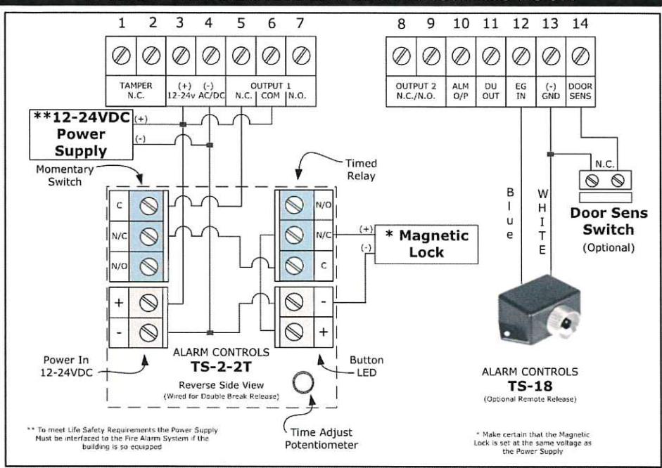
BASIC WIRING DIAGRAM FOR A MAGNETIC LOCK
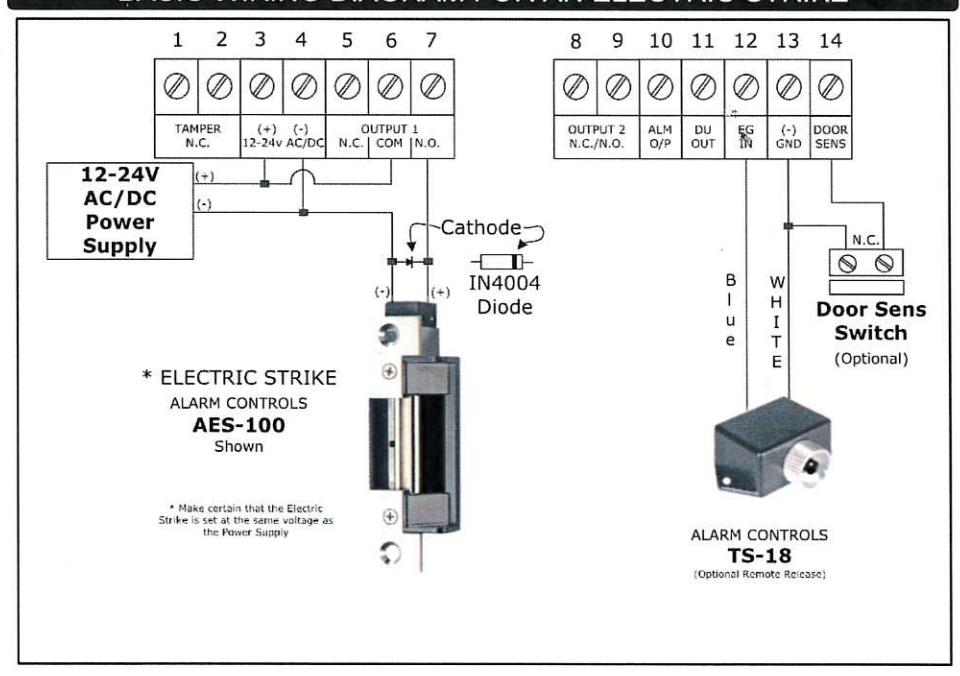
BASIC WIRING DIAGRAM FOR AN ELECTRIC STRIKE
ADDITIONAL WIRING DIAGRAMS
Call tech support 800.624.5625—Follow "2" prompt to Technical Support.
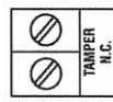
TAMPER SWITCH
The Tamper Switch is Normally-closed when the keypad face plate is securely attached to the back box. Connect these terminals to an alarm panel if desired.
AUTO FULL
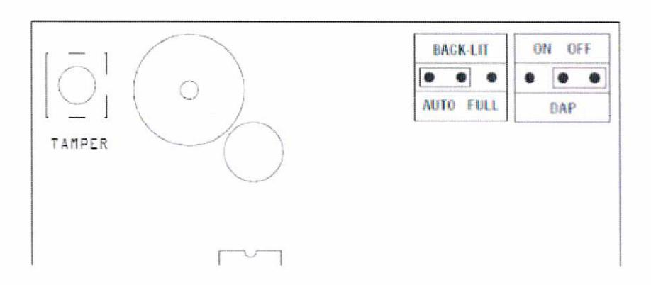
BACKLIGHT ADJUSTMENT
BACK LIGHTING (BACK-LIT JUMPER SELECTION
- FULL BACKLIT The keypad gives dim backlit in standby. It turns to full backlit when a key button is pressed, then back to dim backlit 10 seconds after the last key button is pressed.
- 2. AUTO BACKLIT The Keypad gives no backlit in standby. It turns to full backlit automatically when a key button is pressed, then back to OFP 10 seconds after the last key button is pressed.
| SPECIFICATIONS | ||
|---|---|---|
| Operating Voltage | 12 or 24 Volts AC or DC Auto-sensing | |
| Maximum Current Draw |
78mA
Relays operating |
|
| Quiescent Current Draw | 16mA | |
| Output 1 Contact Rating | 1A@24VDC, Single Pole Double Throw | |
| Output 2 | 1A/24VDC. Jumper Selectable. Normally Open or Normally closed Dry Contacts | |
| Operating Temperature | -4°F to 158°F (-20°C to +70°C) | |
| Ambient Humidity | 5% to 95% Relative Humidity (Non-condensing) | |
| Environmental Rating | Conforms to IP65 | |
| Dimensions | 3.187"W x 4.75"L x 0.6"D | |
CODES
It is recommended that the Installer Code and User Codes be noted here for reference.
| Installer Code | |
| User Code | |
| User Code | |
| User Code | |
| User Code | |
| User Code | |
| User Code | |
| User Code | |
| User Code | |
| User Code | |
| User Code | |
| User Code | |
| User Code | |
| User Code | |
| User Code | |
| User Code | |
| User Code | |
| User Code | |
| User Code | |
| User Code | |
| User Code |