Alarm Controls Backlit Digital Keypad Model KP-100 Installation Instructions
Open the original PDF document
View PDFKP-100A BACKLIT DIGITAL KEYPAD
FOR ELECTRIC LOCK AND SECURITY SYSTEM INSTALLATIONS
Alarm Controls
10027 S. 51st Street, Ste. 102 Phoenix, AZ 85044 800.0645.5538 alarmcontrols.com
ASSA ABLOY, the global leader in door opening solutions
TABLE OF CONTENTS
| INTRODUCTION | |
|---|---|
| SPECIFICATIONS | |
| INSTALLATION | |
| Precautions ···· | |
| CONNECTION TERMINALS | |
| LED INDICATORS & KEYSTROKE ECHO TONES | |
| On-Board LED Indicators | |
| Keystroke Echo Tone & The LED Signals | |
| PREPARATION FOR PROGRAMMING | |
| A) Criteria for Codes | |
| B) List of User Information | |
| PROGRAMMING AND OPERATION9- | |
| Power-Up The Keypad ····· | |
| Set Keypad in Programming Mode with One Time Master Code | - 9 |
| Direct Access to Programming Mode with The "DAP" Code – 2 8 2 8 | |
| System Refreshing with "Refreshing Code" 9 9 9 9 | |
| The Default Values of The Keypad | |
| Master Code ····· | |
| Supervisor Code | |
| Operation and Functions of The Supervisor Code | |
| User Codes - How to Add or Delete | |
| Visitor Codes | |
| Output Modes & Timing ····· | |
| Personal Safety And System Lock-Out ····· | 20 |
| User Code Entry Mode - Auto or Manual | 21 |
| Keystroke Echo Tones On-Off Selection | 21 |
| Relay Output Operation Announcer | |
| Status LED Flashing On-Off during Standby ····· | |
| Intelligent Egress Button – An Unique Feature of A Contemporary Keypad23- | 24 |
| Where And Why "Going Out" Needs Attention23- | |
| Egress Delay , Warning And Alarm25- | |
| Close Programming Mode | |
| PROGRAMMING SUMMARY CHART28- | |
| APPLICATION EXAMPLE ····· | |
| BASIC WIRING | |
| Magnetic Lock | |
| Flectric Strike | 32 |
INTRODUCTION
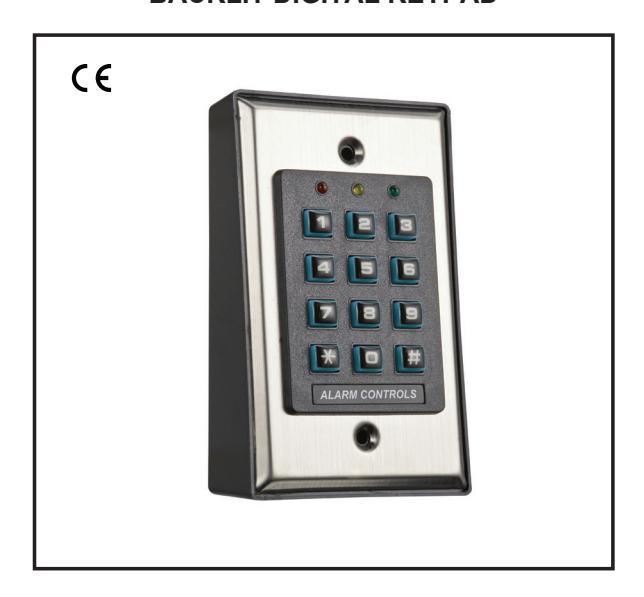
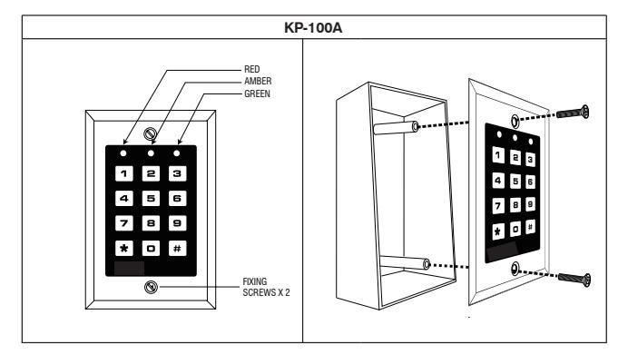
KP-100A is a self-contained digital access control keypad mainly designed for controlling an electric door lock. It can be either flush mounted on a single gang box or surface mounted on its plastic mounting box.
The keypad is ideal for access control and alarm system arm-disarm control. It is also a programmable industrial timer (from 1 second to over 24 hours) for automatic door operator system.
FEATURES
- Loaded with the 2nd generation KP-100A operation software
- Controls "Entry" with User Codes and "Exit" with programmable egress button feature
- Total 1,000 User Codes for door lock control and 50 visitor codes
- Indoor installation
- Stainless steel faceplate combines with plastic mounting box
- Blue backlit keys
SPECIFICATIONS
Operating Voltage:
12-24V AC/DC 10%
Operating Current:
40mA (quiescent) to 70mA
Operation Temperature:
-20 C to +70 C
Environmental Humidity:
5-95% relative humidity non-condensing
Working Environment:
Indoor use only
Number of Users:
Output 1 – 1,000
Number of Visitor Codes:
50, programmable for one time or with the time limit
Timing for Code Entry:
10 seconds waiting for next digit entry
The Timer:
1-99,999 Seconds (Over 24 Hours possible) Programmable Timer
Egress Button:
Programmable for Instant, Delay with Warning Momentary or Holding Contact for the Exit Delay
Output Contact Ratings:
Output Relay 1 – Form C dry contacts, 5A/30 VDC Max. Tamper Switch – N.C. dry contact, 50mA/24VDC Max.
Dimensions: (Includes ABS Plastic box)
4.60(H) x 2.91(W) x 1.89(D) inch
117(H) X 74(W) X 48(D) mm
Weight:
200g net 7.05 oz
Housing:
ABS Plastic Box
Specifications are subject to change for modification without notice
INSTALLATION
ASSEMBLY
PRECAUTIONS
Prevent Accidental Short Circuit:
In the previous experience, most of the damages caused in the installation are accidental touching of the components on circuit board with the wires carrying power. Please be patient to study the manual to become familiar with the specifications of the system before starting the installations.
- Do not apply power to the system while it is being installed.
- Check carefully all the wiring is correct before applying power to the system for testing.
CONNECTION TERMINALS
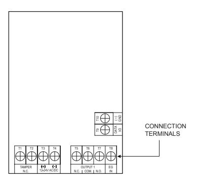
1 - 2 : TAMPER N.C. (Tamper Switch Normally Closed Contact)
A normally closed dry contact while the keypad is secured on its box. It is open while keypad is separated from the box. Connect this N.C. terminal to the 24 hour protection zone of an external alarm system if necessary.
3 - 4 : 12-24V AC/DC (Power Input)
Connect to 12-24V AC or DC power supply. The (-) supply is the common grounding point of the keypad system. No selection jumper is required for the full input voltage range.
Connect DC power with the (+) and (-) polarity indicated; there is no polarity discrimination for AC power input.
5 - 6 - 7 OUTPUT 1 (RELAY OUTPUT)
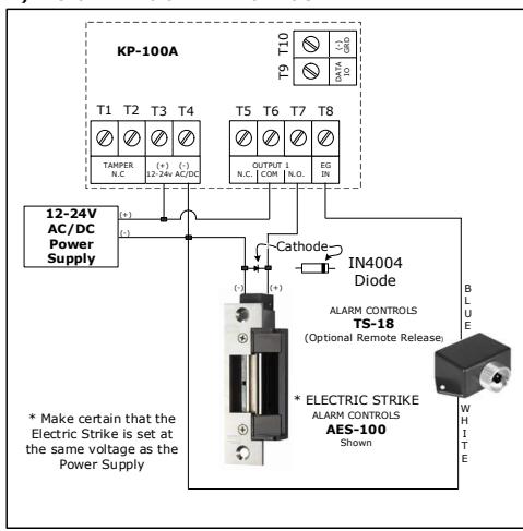
5 Amp relay dry contacts, recommended for door strike controls. A Form-C relay with Common, Normally Open, and Normally Closed contacts. Use N.O. output for Fail-secure locking device and N.C. output for Fail-safe locking device. The relay can be programmed in Start/Stop (toggle) mode or time release mode.
See programming Function 51 (Page 19) for the details.
8 : EG IN ( Egress Input)
A Normally Open (N.O.) input terminal referenced to (-) ground. With the help of connecting a normally open button to activate Output 1 for opening the door.
Egress button is usually put inside near the door. More than one egress button can be connected in parallel to this terminal. Leave this terminal open if not used.
See Programming Function 90 (Page 25) for more information about the Egress Button with programmable features.
9 : Data I/O Port
A bi-directional data communication port prepared for the connection of future features.
10 : (−)GND
(−) Common ground.
LED INDICATORS & KEYSTROKE ECHO TONES
ON-BOARD LED INDICATORS
GREEN (Right) --- It lights up in Green for Output relay activation
AMBER (Center) --- It flashes in Standby. It shows the system status in synchronization with the echo tones. The standby flashing can be turned OFF with programming. See Function 73 (Page 22) for the details.
RED (Left) --- It lights up in Red while output relay is inhibited. It is flashing during inhibition paused.
KEYSTROKE ECHO TONES & THE LED SIGNALS
The buzzer and the amber LED indicator give following echo tones and signals respectively for system status:
| STATUS | ECHO TONES * | AMBER LED |
|---|---|---|
| 1) In Programming Mode | ON | |
| 2) Successful Key Entry | 1 Tone | 1 Flash |
| 3) Successful Code Entry | 2 Tones | 2 Flashes |
| 4) Unsuccessful Code Entry | 5 Tones | 5 Flashes |
| 5) Power Up Delay | Continuous Tones | Continuous Flashes |
|
6) Output Relay
Activation ** |
1 Second Long Tone | |
| 7) In Standby *** | 1 Flash in 1 Second Interval | |
| 8) System Refreshing |
Fast Flashes for
2.5 Minutes |
|
| 9) Code Already Stored in System | 1 Long Tone |
NOTE:
- * All keystrokes Echo Tones can be ON or OFF through the programming option see Function 71 (page 21)
- * * The Output Relay Activation Tone can be selected through the programming option at Function 72 (page 22)
- * * * The Standby flashing can be turned ON or OFF through the programming option at Function 73 (page 22)
PREPARATION FOR PROGRAMMING
A) CRITERIA FOR CODES
Prime Codes
- a) User Codes
- b) Master Code
- c) Supervisor Code
- d) Visitor Codes
All these codes MUST be unique. It is not allowed to repeat a prime code for second function.
All the codes in this system can be 4-8 digits for Manual Entry Mode. The codes must be in the same digit length as the Master Code for Auto Entry Mode. See Function 70 (Page 21) for the details.
NOTE:
The keypad will reject repeated use of prime code in programming and give one long Echo Tone indication.
B) LIST OF USER INFORMATION
The keypad can accommodate up to 1,000 users. To avoid confusion and for programming convenience, it is suggested to make a list of the user information. It helps the owner to program the user codes smoothly and to trace them in the future. Here is a suggested format of the list.
List of Users (See page 15-16 for reference)
Example:
| User | Name | Function | User ID | Code | Remark |
|---|---|---|---|---|---|
| 1 | John | 10 | 001 | 3456 | Output 1 |
| 2 | May | 10 | 002 | 1234 | Output 1 |
| 3 | Tom | 10 | 003 | 24680 | Output 1 |
| 4 | Tracy | 10 | 004 | 13579 | Output 1 |
| 5 | |||||
| 6 | |||||
| 7 | |||||
| 8 | |||||
| 9 | |||||
| 10 | |||||
| 11 | |||||
| 12 | |||||
| 13 | |||||
| 14 | |||||
| 15 | |||||
| 16 | |||||
| 1,000 |
PROGRAMMING & OPERATION
POWER-UP THE KEYPAD
The keypad gives power-up delay of 1 minute after power has been applied. It is the time frame designed for setting the keypad to programming mode with DAP code. See the details of "DAP CODE – 2 8 2 8" below.
- 1) The keypad gives continuous Echo Tones for 1 minute after power-up.
- 2) The power-up delay can be stopped instantly with if the delay Echo Tone is found unpleasent and setting the keypad to programming mode with DAP code is not required. 12#
| POWER-UP DELAY STOP | VALIDATION |
|---|---|
|
1
2 |
# |
| NOTE: Use this code only after a power outage |
3) The keypad will set itself to Normal Operation Mode automatically after the 1 minute power-up delay expired or it is stopped with . 12#
SET KEYPAD IN PROGRAMMING MODE WITH ONE TIME MASTER CODE
- INITIAL SET UP ONLY
It is always necessary to set the keypad in programming mode for feature programming
The keypad is in normal operation after power-up delay. Set it in programming mode with Master Code and validate it with .

NOTE:
- a) For the owner's convenience in programming at the first time, a one time Master Code 0 0 0 0 has been put into the keypad beforeleaving the factory. It is NOT a default code. For security reasons, owner must program a personal Master Code to replace it when the keypad is installed.
- b) The Main LED (amber) is ON after the keypad confirms it in programming mode with 2 Echo Tones. Now go to "Function 01" (page 12) and program in your new Master Code.
- c) DO NOT turn off power while the keypad is in programming mode. Otherwise, it may cause an error to the data in memory.
DIRECT ACCESS TO PROGRAMMING MODE WITH "DAP" CODE -- 2 8 2 8
In case the Master Code is forgotten, apply the following procedures precisely to set keypad into programming mode with DAP code:
- Switch OFF all the power for 1 minute to ensure that the keypad is fully discharged.
- Switch ON power again. The keypad will be in Power-up Mode for 1 minute. The keypad will give a continuous Echo Tone and the Status LED will be flashing. This is the only time frame to accept the DAP code.
- 3) Press the Egress Button (the button connecting across EG IN, (Terminal 8) and (-) GND, (Terminal 2) once to enable the keypad to accept a DAP code. The power-up Echo Tone stops after the Egress Button is pressed. If not using the Egress Button Function, simply apply a momentary jumper between EG IN and (-), such as a piece of wire.
- 4) Key in the DAP code and validate it with . The yellow Status LED is ON steady the and keypad is in programming mode like using Master Code. It is ready to accept new programming data as long as you like until exiting program mode.
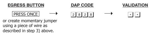
5) To program a new Master Code to replace the old one. See " Record A Master Code " stated at "Function 01" (Page 12) for the details.
NOTE:
The keypad will set itself to normal operation mode, 1 minute after power-up, if the Egress Button is not pressed and the DAP code is not keyed in. To set keypad back to power-up mode, repeat procedures 1-4.
SYSTEM REFRESHING WITH "REFRESH CODE" --- 9 9 9 9
The keypad can be refreshed by cleaning all the programmed old data and set it back to default values except the Master Code .

NOTE:
- a) Make sure that system refresh is really required before entering the refresh code.
- b) Refreshing takes several minutes. The status LED (amber) keeps flashing during refresh.
- The keypad is back to its default value after the refresh. Re-programing of the desired values will be necessary.
THE DEFAULT VALUES AFTER REFRESHING
| FUNCTION | PARAMETERS | DEFAULT FUNCTIONS & VALUES |
|---|---|---|
| 0 1 | Master Code | 0 0 0 0 Factory Set, Not a default value * |
| 0 2 | Supervisor Code | Nil User Program Required |
| 1 0 | User Codes for O/P 1 | Nil User Program Required |
| 4 0 | Visitor Codes | Nil User Program Required |
| 5 1 | O/P Mode of The O/P 1 | Time = 5 Sec, Momentary |
| 6 0 | Wrong Code & Keypad Lock-out | Code = 1, 10 False Code Lock-out 60 Sec |
| 7 0 | User Code Entry Mode | Code = 2, Manual Entry Mode |
| 7 1 | Keystroke Echo Tones ON-OFF Selection | Code = 1, Pacifier Tone ON |
| 7 2 | O/P Operation Announcer | Code = 1 Sec, Notification Beep ON |
| 7 3 |
Status Amber LED Standby
Flashing ON-OFF |
Code = 1, Flashing Enabled |
| 9 0 | Egress Delay & Warning | Code 1 = 0, Instant, No Delay |
| Code 2 = 1, Momentary Contact without Warning |
NOTE:
The DAP Code 2 8 2 8 and the Refreshing Code 9 9 9 9 are fixed in the operating system program. It can not be changed.
MASTER CODE (Function 01)

(1) FUNCTION
Key in Location 01
(2) MASTER CODE
- Master Code is the authorization code for setting the system to programming mode. It will not operate the output relay like an User Code.
- The Master Code can be 4 to 8 digits.
- When a new master code is entered in and confirmed, the old master code is overwritten and replaced.
(3) VALIDATION
Press key once. Two-Echo Tones confirms the entry.
Example:
Set a Master Code "2 2 3 3" ----
Press * * to exit Programming mode unless you wish to continue to next desired programming function. Two Echo Tones and flashing yellow LED indicates that you have exited programming mode.
SUPERVISOR CODE (Function 02)
The Supervisor Code can operate the output relay like an user code, it can toggle the output relay and it can lockout (inhibit) all users codes.

(1) FUNCTION
Key in Function 02
(2) SUPERVISOR CODE
- The Supervisor Code can be 4 to 8 digits.
- When a new Supervisor Code is keyed in and confirmed, it will overwrite and replace the previous Supervisor code.
(3) VALIDATION
Press key to confirm code entry. #
Example:
- a) Set a Supervisor Code "2 5 8 0" ----
- b) Deleted a Supervisor Code from memory: Key in the Location number and #. ----
OPERATION AND FUNCTIONS OF THE SUPERVISOR CODE
1) Operate Relay Output Supervisor
The operation of the Supervisor Code is just like a normal User Code. Simply key-in the Code with number 1 for the relay output. The Supervisor Code can also be used to reset an operating output timer instantly.
| SUPERVISOR CODE | Output 1 Activates for preset unlock time |
|---|---|
| (like a normal User code) |
Optional Functions Controlled by Supervisor Code
Apart from controlling of the output relay; the Supervisor Code can also be used to enable the optional functions controlling the Output relay for user convenience or security enhancement.
Supervisor Code and Egress Button are excluded from any system inhibition and lockup functions; they are valid for door open at anytime for safety.
2) Override The Door Lock Controlled by Output Relay (Keep Door Un-locked) Toggle Mode
The Output Relay is usually for door lock control. In some situations, the door may require un-locked for a period of time to allow door opening without User Code for entry / exit convenience. This function Starts / Stops the toggle mode with the following code entry.
| SUPERVISOR CODE | The Door is Un-locked, or Toggled |
|---|---|
|
Until
SUPERVISOR CODE |
Is used to re-lock the door |
NOTE :
- ‧ The door is un-locked while the function is enabled. The "Output" LED (Green) turns ON.
- ‧ Do not forget to stop this function after use because the door is un-locked. Also, the system refuses the optional functions (3) & (4) while Override function comes into effect.
- ‧ This feature is good for all DC locks rated for continous duty.
- ‧ Do not use this feature on any AC powered locking devices.
4) Lockout All The User Codes for Output Relay (Disable Access Control Manually)
To enhance the security of the access control keypad, the owner can disable the keypad after office hours, etc. The Output (for door lock control) is inhibited, all the User Codes for it become invalid and those people holding a User Code are refused. This function Starts / Stops with the following code entry.
| SUPERVISOR CODE | User Code Operation Inhibited, Start / Stop |
NOTE :
- ‧ The door is locked during Output Relay inhibited and the "INHIBIT" LED (Red) is ON. Attempting to input an User Code will cause the yellow LED to flash five times and the Echo Tones will sound five times rapidly.
- ‧ Lockout applies to all User Codes for Output relay.
USER CODES FOR OUTPUT RELAY (Function 10)
Total 1,000 User Codes are available for controlling the output relay.
Enter programming Mode by entering Master Code and * *
FUNCTION MEDIA USER ADDRESS USER CODE VALIDATION (1) (2) (3) (4) (5)
(1) FUNCTION
10 – Group 1 – 1,000 User Codes for controlling Output 1
(2) MEDIA (Operation Media)
- 2 Add User Codes 4-8 Digits **You may want to review Function 70 (page 21) at this time**
- 5 Delete User Codes from the selected User ID Delete an User Code by keying-in its address number.
- 0999 Group Clearing. Clear all the User Codes of the selected User Group Location. Clearing takes few seconds to a minute.
(3) USER ID (The IDs of The User Codes)
000 – 999 – 1,000 User addresses for the User Codes in User Group 1 (Output Relay).
(4) USER CODE
Key in User Code into each assigned User ID.
(5) VALIDATION
Press the key once. Two-Echo Tones confirms the entry.
When finished press * * to exit programming mode.
1) Example 1 -- Enroll An User Code:
i) Programming :
(a) (b) (c) (d) (e)
- (a) The User Code is programmed for operating Output 1
- (b) The operation medium is Private User Code only
- (c) Take ID number 001 in Group 1 to store the User Code, which is one of the IDs in 000-999. Total 1,000 user codes be enrolled.
- (d) Put Private User Code "1 2 3 4" into the storage location
- (e) Press # to store the "Private User Code", two-Echo Tones confirms a valid entry
ii) Operation : (while the system is back to operation mode)
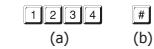
- (a) Key in the Private User Code "1 2 3 4"
- (b) Confirm it with the # key. Output 1 activates
2) Example 2 -- Delete An User Code:
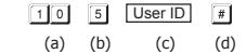
- (a) Key in the User Group that the User ID belongs to. "10" for Group 1
- (b) Key in "5" that is the Command Code for making a deletion
- (c) Key in the User ID that stored the User Code
- (d) Press the # key. Two-Echo Tones confirms a valid entry and the User Code in that User ID is cleared
3) Example 3 – Clear The Whole Group of Users :
Whole group of User Codes can be cleared with the following command.
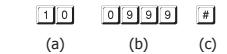
- (a) The User Group 1 "10" is selected to be cleared
- (b) Key in the Group Deletion Command, 0 9 9 9
- (c) Confirm the deletion with #. All the User Codes in Group 1 are cleared. It takes few seconds to several minutes to complete depending on the data stored
VISITOR CODES FOR OUTPUT 1
(Function 40)
The Visitor Codes are temporary user codes for Output 1 (mainly for door strike in access control). They can be programmed as "One Time Codes" or "Codes with Time Limit". The Visitor Codes will be cleared automatically after use if they are one time codes, or, when the allowed time expires. Read this entire section prior to programming a Vistor Code.
Enter Programming Mode by entering Program Code and * *.

(1) FUNCTION
Key in Function 40
(2) VISITOR ID
01 - 50 --- 50 Visitor IDs for the 50 visitor codes. They are Two-digit numbers
0 9 9 9 = Clear all the Visitor Codes in Function 40. Please see the Programming example below for the details.
(3) VALID PERIOD
The codes in this box MUST be two digits and they represent the time of operation.
0 0 --- One Time Code
One Time Code has no time limit but it can only be used for ONCE. It is cleared by the system automatically after use.
0 1 - 99 --- Time Limit in Hour(s)
The Visitor Code can be set with the valid time limit of 1 Hour to 99 Hours with a two-digit number of 01 to 99. The visitor code is cleared by the system when the time limit is reached.
(4) VISITOR CODES
- The Visitor Codes can be 4-8 digits for Manual Mode code entry.
- The Visitor Codes MUST be in the same digit length with the Master Code for Auto Mode code entry.
- The Visitor Codes can not reset Duress Output.
- When a new Visitor Code is put in the same Code box, the old code is replaced.
NOTE: All Visitor Codes will be cleared after power down to prevent extension/confusion of their valid time limit.
(5) VALIDATION
Press # key once. Two-Echo Tones confirms the entry.
EXAMPLES:
Example 1: Set a "One Time Visitor Code" with the number of "1 2 6 8" for the Output 1 (a) (b) (c) (d) (e) (a) Visitor Code Programming, (b) The Visitor ID, (c) An One Time Code, (d) The Visitor Code, (e) Example 2: Set a "Visitor Code" with the number of "1 3 7 8" that is valid for three hours Entry Confirmation
(a) (b) (c) (d) (e)
(a) Visitor Code Programming, (b) The Visitor ID, (c) Valid for 3 Hours, (d) The Visitor Code, (e) Entry Confirmation
Example 3: Delete a "Visitor Code" from Vistor ID 02 in the memory
(a) (b) (c)
(a) Visitor Code Programming, (b) The Visitor ID, (c) Delete Confirmation
Example 4: Clear all "Visitor Codes" in Location 40
(a) (b) (c)
(a) Visitor Code Function, (b) The Deletion Command Code, (c) Confirmation, all Visitor Codes are cleared
When finished press * * to exit Programming Mode
Enter Programming Mode by entering Program Code and * *
The keypad output is programmable for Start/Stop or Timing modes. Apart from door access control, alarm arm-disarm control, there is also an universal timers for automatic operators with up to 99,999 seconds (over 24 hours) of programmable unlock time.

(1) FUNCTION
-- Function for Output 1
(2) OUTPUT MODE & TIMING
Toggle Mode
The number 0 sets the output to Toggle mode . The output Starts when an User Code is entered; the output Stops when an User Code is entered again. Note: This is similar to the function of the Supervisor code, but now "ALL" User Codes will toggle the output relay.
-- Seconds Momentary --- (Default -- Momentary 5 Seconds)
The output can be set in Momentary Mode with the time of 1 second to 99,999 seconds. The output will reset automatically when the time expires.
(3) VALIDATION
Press key once. Two-Echo Tones confirms the entry.
When finished Press * * to exit Programming Mode.
RESET OUTPUT TIMER WITH SUPERVISOR CODE
If you have a extremely long time set on the Output Timer it can be RESET manually at anytime with the Supervisor Code that operates the output before the end of the time. This procedure can take the keypad out of Toggle Mode.
Example:
Reset Output Relay Timer -- SUPERVISOR CODE ---------- Output Relay stops
Enter Programming Mode by Entering Program Code and * *

(1)FUNCTION
Key in Funtion 60
(2) LOCK-UP OPTIONS
The Options are represented by the following Numbers. They are described below:
- 1 --- After 10 successive false User Code trials, the keypad locks for 60 seconds. -- (Default)
- 5 10 --- Selection of after 5 to 10 successive false User Code trials, the keypad locks for 15 minutes. The keypad can be reset to release the lock-up with the "Supervisor Code" in the following way.
Example: Release the lock-up -- SUPERVISOR CODE
00 --- Remove all the above lock-up securities.
(3) VALIDATION
Press key once . Two-Echo Tones confirms the entry
When finished press * * to exit Programming Mode
USER CODE ENTRY MODE – Auto or Manual (Function 70)
Enter Programming Mode by entering Program Code and * *
| (1) FUNCTION | FUNCTION | ENTRY MODES | VALIDATION |
|---|---|---|---|
|
70
Key in Function |
70 | 1 or 2 | # |
| (1) | (2) | (3) |
(2) USER CODE ENTRY MODES
Two modes 1 and 2 are available for User Code entry options.
1 --- Auto Entry Mode
Auto Entry Mode requires no pressing of the # key after code entry for code checking.
In the Auto Entry Mode, the User Codes MUST be set in the same digit length of the Master Code (For example, if the Master Code is 5 digits, then all User Codes must be in 5 digits as well. All other User Codes not in 5 digits become invalid). When the number of digits reaches, the system will check the User Code automatically. Good for high traffic access control.
2 --- Manual Entry Mode – (Default)
Manual Entry Mode always requires the # key following the User Code for code checking. The User Codes can be 4-8 digits arbitrary and they are NOT required to be in the same digit length of the Master Code. Manual Entry increases the level of security in code trial by the unauthorized people.
(3) VALIDATION
Press key once . Two-Echo Tones confirms the entry
When finished press * * to exit Programming Mode
KEYSTROKE ECHO TONES ON-OFF SELECTION (Function 71)
Enter Programming Mode by entering Program Code and * *
(1) FUNCTION Key in Function VALIDATION 71 1 or 0(2) (3) FUNCTION FUNCTION MODES # 71
(2) FUNCTION MODES FOR KEYSTROKE ECHO TONES
Keystroke Echo Tone is the Echo Tones from the keypad, which include the tones of Successful Key entry (1 Echo Tone) and the Unsuccessful User Code entry (5 Echo Tones).
NOTE:
The Echo Tones for the Warning and the Power-up Delay do not belong to Keystroke Echo Tones and can not be OFF.
1 --- Keystroke Echo Tone ON – (Default)
All the Keystroke Echo Tones available from the keypad are enabled. They are the response tones indicating the operation status of the keypad after a User Code is entered.
0 --- Keystroke Echo Tone OFF
Turning the Keystroke Echo Tones are OFF maybe requested for a place that needs a silent environment.
(3) VALIDATION
Press key once. Two-Echo Tones confirms the entry.
When finished press * * to exit Programming Mode.
RELAY OUTPUT OPERATION ANNOUNCER Enter programming mode by entering Program Code and ** (1) FUNCTION FUNCTION FUNCTION FUNCTION FUNCTION FUNCTION FUNCTION FUNCTION FUNCTION FUNCTION FUNCTION FUNCTION FUNCTION FUNCTION FUNCTION FUNCTION FUNCTION FUNCTION FUNCTION FUNCTION FUNCTION FUNCTION FUNCTION FUNCTION FUNCTION FUNCTION FUNCTION FUNCTION FUNCTION FUNCTION FUNCTION FUNCTION FUNCTION FUNCTION FUNCTION FUNCTION FUNCTION FUNCTION FUNCTION FUNCTION FUNCTION FUNCTION FUNCTION FUNCTION FUNCTION FUNCTION FUNCTION FUNCTION FUNCTION FUNCTION FUNCTION FUNCTION FUNCTION FUNCTION FUNCTION FUNCTION FUNCTION FUNCTION FUNCTION FUNCTION FUNCTION FUNCTION FUNCTION FUNCTION FUNCTION FUNCTION FUNCTION FUNCTION FUNCTION FUNCTION FUNCTION FUNCTION FUNCTION FUNCTION FUNCTION FUNCTION FUNCTION FUNCTION FUNCTION FUNCTION FUNCTION FUNCTION FUNCTION FUNCTION FUNCTION FUNCTION FUNCTION FUNCTION FUNCTION FUNCTION FUNCTION FUNCTION FUNCTION FUNCTION FUNCTION FUNCTION FUNCTION FUNCTION FUNCTION FUNCTION FUNCTION FUNCTION FUNCTION FUNCTION FUNCTION FUNCTION FUNCTION FUNCTION FUNCTION FUNCTION FUNCTION FUNCTION FUNCTION FUNCTION FUNCTION FUNCTION FUNCTION FUNCTION FUNCTION FUNCTION FUNCTION FUNCTION FUNCTION FUNCTION FUNCTION FUNCTION FUNCTION FUNCTION FUNCTION FUNCTION FUNCTION FUNCTION FUNCTION FUNCTION FUNCTION FUNCTION FUNCTION FUNCTION FUNCTION FUNCTION FUNCTION FUNCTION FUNCTION FUNCTION FUNCTION FUNCTION FUNCTION FUNCTION FUNCTION FUNCTION FUNCTION FUNCTION FUNCTION FUNCTION FUNCTION FUNCTION FUNCTION FUNCTION FUNCTION FUNCTION FUNCTION FUNCTION FUNCTION FUNCTION FUNCTION FUNCTION FUNCTION FUNCTION FUNCTION FUNCTION FUNCTION FUNCTION FUNCTION FUNCTION FUNCTION FUNCTION FUNCTION FUNCTION FUNCTION FUNCTION FUNCTION FUNCTION FUNCTION FUNCTION FUNCTION FUNCTION FUNCTION FUNCTION FUNCTION FUNCTION FUNCTION FUNCTION FUNCTION FUNCTION FUNCTION FUNCTION FUNCTION FUNCTION FUNCTION FUNCTION FUNCTION FUNCTION FUNCTION FUNCTION FUNCTION FUNCTION FUNCTION FUNCTION FUNCTION FUNCTION FUNCTION FUNCTION FUNCTION FUNCTION FUNCTION FUNCTION FUNCTION
(2) FUNCTION MODES FOR OUTPUT ANNOUNCER
Output announcer gives notification Echo Tone on the operation status of the output relay. There are two notification modes available for the selection. The notification can also be OFF while the Keystroke Echo Tone OFF mode is selected. See Function 71 (Page 21).
No Notification
The output operation notification is OFF but does note affect the normal Keystoke Echo tones. Note: The green LED will stay illuminated for the entire length of time that the relay is energized.
1 --- 1 Second Long Notification -- (Default)
1 second notification Echo Tone is given when the output relay activates. It is prepared to notify the person outside the door when the lock is released and the door can be opened. It is good for door lock that gives no sound when it activates, such as a magnetic lock. Note: The green LED will stay illuminated for the entire length of time that the relay is energized.
2 --- 2 Short Beeps Notification
2 short Echo Tones. Echo Tones sound when the output relay activates. Note: The green LED will stay illuminated for the entire length of time that the relay is energized.
(3) VALIDATION
Press # key once . Two-Echo Tones confirms the entry
When finished press * * to exit Programming Mode.
STATUS LED FLASHING ON-OFF DURING STANDBY
(Function 73)
Enter Programming Mode by entering Program Coe and * *
| (1) FUNCTION | FUNCTION | FUNCTION MODES | VALIDATION | |
|---|---|---|---|---|
| Key in Function 7 3 | 73 | 1 or 0 | → | # |
| (1) | (2) | (3) |
(2) FUNCTION MODES FOR STANDBY FLASHING LIGHT
Some people find the flashing light of the status LED (the amber LED) is unpleasent during standby, especially at the night time. The standby flashing can be ON-OFF with the setting here.
1 --- Standby Flashing ON -- (Default)
The Status LED gives Standby Flashing all the time. It also gives the light indications showing the operation status of the system.
O --- Standby Flashing OFF
The Standby Flashing is OFF but it does not affect the system status indications.
(3) VALIDATION
Press # key once . Two-Echo Tones confirms the entry
When finished press * * to exit Programming Mode.
INTELLIGENT EGRESS BUTTON – AN UNIQUE FEATURE OF THE KEYPAD INTRODUCTION
Most of the keypads for access control are just for controlling "Entry" from the outside. It is not enough for today's access control systems. In fact, controlling "Exit" is also very important in some public passage areas that are not allowed to use locks or digital keypads that prohibit "Exit" due to safety reasons. Such as hospitals, pre-schools, retirement homes, convenience stores, emergency exits etc.. The wardens, teachers, shopkeepers and the guards are always required to keep an eye on people to prevent unattended leaving, shoplifting, and unauthorized use of the emergency exits.
The Intelligent Egress Button can be programmed to get attention of the person on duty before the door is opened. The button offers programmable egress delay, delay with warning, holding button for the delay, momentary button contact with warning for the delay and even gives an alarm when a controlled door is opened.
See "Function 90" (Page 25) for setting the desired functions for the Egress Button.
The functions programmed to the Egress Button do not affect the normal operation of the keypad. The operation of the keypad with Code is always in the first priority to give instant action to the output relay for for operating the electric locking device.
It is NOT required to program the Egress Button with the special function in normal use. Just leave it on its default values.
WHERE AND WHY "EXITING" NEEDS ATTENTION
Examples for some areas may need an Intelligent Egress Button:
Hospital:
Some of the patients are not allowed to leave the ward without staff permission. An egress button with exit delay and warning Echo Tones will help the nurse or staff to get attention to the door when the egress button is pressed. Further setting of the egress button with holding contact delay even gives higher level of security to a controlled door.
Pre-School:
Young children are always active. For safety reasons, teachers have to watch all of them in the attended area. Exiting alone without parents or teacher is dangerous to young children. An egress button with delay and warning Echo Tones will be helpful to prevent the children trying to exit without getting the attention of the teacher.
Retirement Home and Memory Care Units:
Some patients need constant attention and care. Some people may have poor memory. They may forget the way to come back if they leave alone. An egress button with delay and warning Echo Tones will easily get the attention of the staff before the door is open.
Convenience Store:
Most of the convenience stores have just only one or two clerks on duty. Shoplifting may easily happen while the clerk is busily serving customers at the cashier's desk. A holding contact egress button with delay and warning Echo Tones may help to stop most of the shoplifting. As the thief knows that he is gotten attention by the shopkeeper before the door is open.
High Traffic Passage:
A short buffer time may be necessary for opening a door outward after pressing the egress button for those exits open to a high traffic passage. An egress button with short delay and warning Echo Tones helps the user to pay attention to the people passing by to prevent hitting them when the door is pushed outward.
Exit Delay:
Emergency Exit is not open to the public for daily use. It is for emergency case only. It is usually closed and watched by guards. The egress button of this keypad can be programmed to offer exit delay with warning Echo Tones and even gives alarm output to trigger an alarm system when the door is forced to open or the door is open after the exit delay expired. It is an useful tool to get attention of the person on duty.
Before enabling the Egress Delay you must check with your local Authority Having Juridication (AHJ) to confirm if this function will be permitted.
EGRESS DELAY, WARNING AND ALARM
(Function 90)
Enter programming mode by entering Program code and * *

(1) FUNCTION
Key in Function 9 0
(2) CONFIGURATIONS OF THE EGRESS WARNING AND ALARM
Key in the number to enable 1 of the configurations described below:
--- Momentary Contact Mode without Warning -- (Default)
- Press the Button once. No warning or alarm is given during Egress Delay.
- Good for silent area. The people have to wait for the door open until the delay time is reached. The default setting on "0" second delay.
--- Momentary Contact Mode with Warning Tones
- Press the Button once. The system gives Warning Tones during the Egress Delay.
- Good for a place requiring attention. The keypad will sound Echo Tones during the delay period and then the door will release.
4 --- Holding Contact Mode without Warning
- Press and hold the Button. No warning or alarm is given during the Egress Delay.
- Good for the silent area. You must press & hold the button until the delay time is reached for the door to release.
--- Holding Contact Mode with Warning Tones
- Press and hold the Button. The system gives Warning tones during Egress Delay.
- Good for a place requiring attention. The keypad will sound Echo Tones while the button is held down until the delay period concludes for the door release.
(3) EGRESS DELAY TIMER
O --- No Delay - (Default)
Output 1 activates instantly (the door is released instantly) when the Egress Button is pressed.
1 - 99 --- Egress Delay Timing
Put a number of 1 to 99 into the box to enable the Egress Delay. The number is the time in seconds, which starts to count when the Egress Button is pressed. Output 1 activates (the door is released) when the delay time is reached.
NOTE: Most juridictions will only permit either 15 or 30 seconds of delay.
NOTE:
- 1) Momentary Contact -- The Egress Delay starts to count when the egress button is momentarily pressed. Output 1 activates automatically (door is released) when the delay time is reached.
- 2) Holding Contact -- The user MUST hold the egress button in contact for the whole period of the Egress Delay time until Output 1 activates. If the egress button is released before the end of the Egress Delay, the timer will stop to count and reset.
For safety, it is necessary to put a sign telling how to open the door if "Holding Contact" is enabled. Check with AHJ for proper sign location and size.
Example: A sign for an egress button that is programmed with "Holding Contact" of 5 seconds.
Press & Hold The Button 5 Seconds Minimum Until The Door Is Open
3) The Egress Delay does not affect the operation of the User Codes for Output 1. The User Codes always give INSTANT action.
(4) VALIDATION
Press key once. Two-Echo Tones confirms the entry
EXAMPLES:
Example 1 : Set Egress Button in Momentary contact of 5 seconds with delay & warning tone
(a) (b) (c) (d)
(a) Egress function programming, (b) Momentary contact with warning, (c) Delay time of 5 seconds to release door, (d) Entry confirmation
Example 2: Set Egress Button in Holding contact of 10 seconds with warning tone
(a) (b) (c) (d)
(a) Egress function programming, (b) Holding contact mode with warning, (c) Holding time of 10 seconds to release door, (d) Entry confirmation
Example 3 : Set Egress Button in Momentary contact without delay (This is the default setting)
| (a) | (b) | (c) | (d) |
(a) Egress function programming, (b) Momentary contact without delay, (c) Release door instantly,
(d) Entry confirmation
When finished press * * to exit PRogramming Mode.
CLOSE PROGRAMMING MODE ( * * )
Always close programming mode with * * to set system back to normal Operation after programming.
VALIDATION
------------------------------- System is back to normal operation mode
PROGRAMMING SUMMARY CHART
| FUNCTION | DESCRIPTION | ENTRY LIMITS & CODE OPTIONS | CODE ENTRY |
FACTORY
DEFAULT |
|---|---|---|---|---|
| 0 1 | Master Code | 4-8 Digits | O 1 MASTER CODE | NIL |
| 0 2 | Supervisor Code | 4-8 Digits | 0 2 SUPERVISOR CODE | NIL |
| 10 | User Codes for O/P 1 |
CODE 1 – MEDIA:
2.—Add User Code 5.—Delete User Code CODE 2 – USER ADDRESS: 000-999—Group 1(10) |
I O CODE1 CODE2 CODE3 | NIL |
|
CODE 3 - USER CODES:
4-8 Digits |
||||
| 40 | Visitor Codes |
CODE 1 - VISITOR ID:
01-50 CODE 2 - VALID PERIOD: 00One Time 01-99 Hours CODE 3 - VISITOR CODE: 4-8 Digits |
4 0 CODE1 CODE2 CODE3 | NIL |
| 5 1 | O/P Mode for O/P 1 |
OUTPUT MODE & TIME:
0 Toggle 199999 Seconds, Momentary |
5 1 O/P MODE & TIME # | 5 Seconds |
| 6 0 |
Wrong Code
Keypad Lockout |
LOCK-UP CODE:
110 Trial, Lock-Up 60 Sec. 5-105-10 Trial, Lock-Up 15 Minutes 00No Lock-Up |
6 O LOCK-UP CODE # |
Code = 1,
10 Trials, Lock-Up 60 Seconds |
| 7 0 | Code Entry Mode |
ENTRY MODE:
1Auto Mode* 2Manual Mode |
7 0 ENTRY MODE # |
Mode =
2, Manual Mode |
| 7 1 |
Keystroke Echo Tone
ON-OFF |
FUNCTION MODE:
0OFF 1ON |
7 1 FUNCTION MODE # |
Mode = 1,
Keystroke Echo Tone ON |
| 7 2 |
Relay Output
Announcer |
FUNCTION MODE:
0NO Notification 11 Second Long Echo Tone 22 Short Echo Tones |
7 2 FUNCTION MODE # |
Mode = 1
1 Second Long Beep |
* Auto Mode requires that all codes - Master, Supervisor, Users, and Vistors Codes must all be the same 4 - 8 digits in length.
STANDARD PROGRAMMING
|
SYSTEM
CODES |
OPERATION | CODE ENTRY | RESULTS |
|---|---|---|---|
| 0000 | Factory Set Master Code for User to set system in programming Mode at the first time. THIS IS NOT A PERMANENT SYSTEM CODE & IT IS CHANGED IF A NEW MASTER CODE IS PROGRAMMED. | OR NEW MASTER CODE |
System in
Programming Mode |
| 9999 | REFRESH CODE Refresh the system and set all its function back to default values. | 9999 |
All programmed
data are cleared and back to the default values except the Master Code |
| 2828 |
DAP CODE Direct access to
programming mode. Valid only in the power-up delay period |
2828 # |
System in
Programming Mode |
| 0999 | USER Codes / Cards whole group clearing Code for the selected Function LOCATIONS: 10— User Group 1 40— Vistor Group | LOCATION NO. 0999 # |
Whole group
of users in the selected location are cleared |
| ** | Exit Programming | •• |
The system back
to normal opration after programming |
SPECIAL FUNCTIONS PROGRAMMING
| FUNCTION | DESCRIPTION | CODED OPERATIONS | CODED ENTRY | RESULTS |
|---|---|---|---|---|
| 7 3 | Standby LED Flashing |
FUNCTION MODE:
0OFF 1ON |
73 FUNCTION MODE # |
Mode = 1,
Flashing ON |
| 90 |
Egress Delay
Warning & Alarm |
CODE 1 – FUNCTION MODE: 1Momentary, No warning 2Momentary, with warning 4Hold Contact, No warning 5Hold Contact, with warning CODE 2 – DELAY TIME: 0No Delay 1-99 Seconds | 9 0 CODE1 CODE2 P |
Mode = 1
Momentary, No warming TIME = 0 No Delay |
APPLICATION EXAMPLE
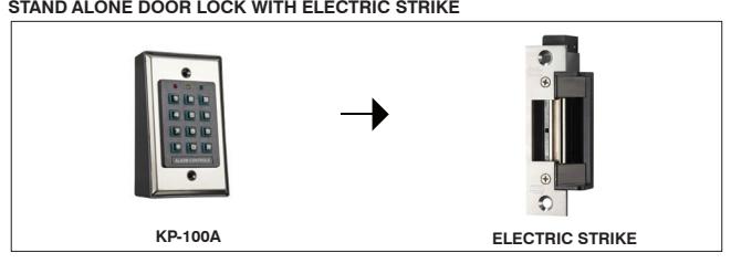
NOTE:
- Connect the 1N4004 as close as possible to the strike in parallel with the Electric Strike power terminals to absorb the counter EMF to prevent it from damaging the keypad.
- To avoid Electro-Static-Discharge from interfering with the operation of the keypad, always ground the (-) terminal of the keypad to earth.
1) BASIC WIRING OF A MAGNETIC LOCK
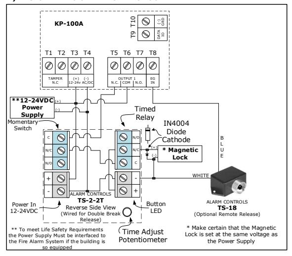
2) BASIC WIRING OF AN ELECTRIC STRIKE