Alarm Controls Access Reader Keypad Model KP-300 Opreating Instructions
Open the original PDF document
View PDFMODEL KP-300 ACCESS CONTROL READER KEYPAD
OPERATING INSTRUCTIONS
Alarm Controls Corporation

19 Brandywine Drive Deer Park, New York 11729
(800) 645-5538
www.alarmcontrols.com
TABLE OF CONTENTS
| Introduction 3 |
|---|
| Features 3 |
| Specifications 4 |
| Installation 5 |
| Precautions 5 |
| Harness Connections 6 |
| LED Indicators 7 |
| Programming Instructions 8 |
| Set Keypad Into Programming Mode With the |
| Installer Code 8 |
| Direct Access to Programming Mode (DAP Code) 8 |
| Refresh Code 8 |
| Default Keypad Value Table 9 |
| Keypad Programming 9 |
| Programming Mode Using Factory Set Installer Code 10 |
| Changing the Installer Code 10 |
| Record an EM Card to Operate Output 1 10 |
| Set User PIN to Operate Output 1 10 |
| Record an EM Card & User PIN to Operate Output 1 11 |
| Record an EM Card & Common User Code to Operate |
| Output 1 11 |
| Close the Programming Mode 11 |
| Operation 12 |
| Unlock Door With an EM Card 12 |
| Unlock Door With a User PIN 12 |
| Unlock Door With an EM Card & User PIN 12 |
| Unlock Door With an EM Card & Common |
| User Code 12 |
| Feature Programming 12 |
| Programming Criteria for Codes 12 |
| Installer Code (Location 01) 14 |
| Common User Code (Location 03, 04) 14 |
| Record/Delete PINs or Cards 14 |
| Visitor Codes (Location 40) 16 |
| Set a One-Time Visitor Code 17 |
| Set a Time Limit Visitor Code 17 |
| Delete a Visitor Code 18 |
| Clear All Visitor Codes 18 |
| Configure Output 1/Output 2 Modes (Location 51,52) 18 |
| Personal Safety and Keypad Lockout (Location 60) 19 |
| User PIN Entry Mode (Location 70) 19 |
TABLE OF CONTENTS (Continued)
| Tone On/Off Selection (Location 71) 20 | |
|---|---|
| Output Automation Announcer (Location 72) 20 | |
| Yellow LED Flashing On/Off | |
| During Standby (Location 73) 20 | |
| Operation Modes (Location 94) 21 | |
| Application Example 21 | |
| Application Hints For the Auxiliary Terminals 22 | |
| Glossary 23 | |
| Programming Summary Chart 24 |
INTRODUCTION
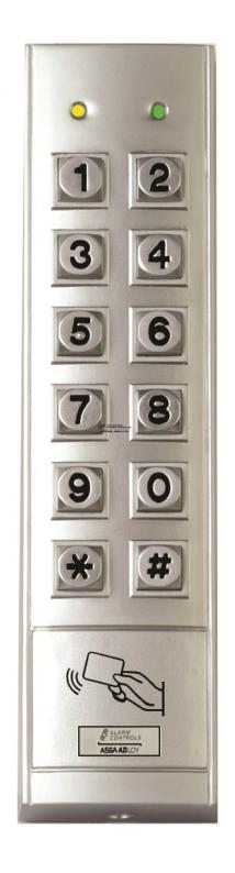
The KP-300 is a weather-proof, vandal resistant, mullion mount keypad. It combines the functions of a digital keypad and proximity EM card reader in one unit.
The KP-300 has been designed to work independently as a stand alone keypad. The keypad has multiple functions that can be programmed to meet a variety of applications.
FEATURES
- Weather-proof to IP65
- Vandal resistant die cast zinc alloy housing
- Metal back lit key buttons for visibility in dark areas
- Mullion surface mount, can be mounted on door frame or wall
- Operates with EM card only, PIN and card or PIN
- Two programmable S.P.D.T. relay outputs
- Output 1 has a capacity of 1000 PINs and/or cards
- Output 2 has a capacity of 100 PINs and/or cards
- Fifty visitor codes, programmable for one time use or with time limit
- Yellow and green LEDs indicate keypad status
- Lifetime limited warranty
SPECIFICATIONS
Operating Voltage ......... 12 VDC Nominal, 11-15 VDC Operating Current .......................60 mA (quiescent) 95 mA (two relays energized) Operating Temperature ................... -20°C to +70°C Environmental Humidity .... 5 - 95% relative humidity,
Working Environment and Ingress
Protection .... Indoor or Outdoor, IP65 Weather-proof Number of Users -
non-condensing
Output 1 has a capacity of 1000 PINs and/or cards Output 2 has a capacity of 100 PINs and/or cards Fifty visitor codes, programmable for one time use or with time limit
Egress Button -
Programmable for Instant, Delay with warning and/or alarm
Momentary or latching contacts for the Exit Delay Output Contact Ratings -
Output Relay 1, N/O and N/C dry contacts, rated 2A @ 24 VDC maximum
Output Relay 2, N/O and N/C dry contacts, rated 1A @ 24 VDC maximum
Dimensions
7-5/64" H x 1-13/16" W x 1" D
Package Contents -
- KP-300 Keypad
- Two EM Cards. Part number EM-10 (additional cards are available)
- Two Mounting Screws and Fasteners
- One 1N4004 Diode
- One Hex Key
- Instruction Manual
INSTALLATION
Front Cover Rear Cover
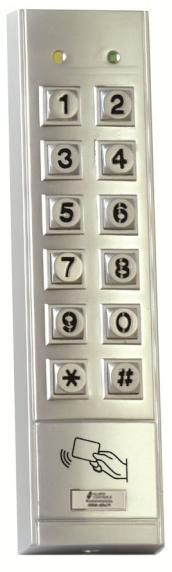
- 1. Remove flat head screw from the bottom of the keypad with the provided hex key.
- 2. Mount the back cover to the door frame or wall.
- 3. Pass the wire harness through the center opening in the back plate.
- 4. Plug the connector at the end of the wire harness into the PCB.
- 5. Place the back cover on the front cover and secure with screw.
PRECAUTION
Prevent Interference
The EM card reader works at a frequency of 125 kHz. Installation precautions are necessary.
Make sure the location for installation has no strong low frequency EM signals in the range of 100 to 200 kHz.
If there is more than one keypad in the installation, be sure that they are at least two feet apart.
HARNESS CONNECTIONS
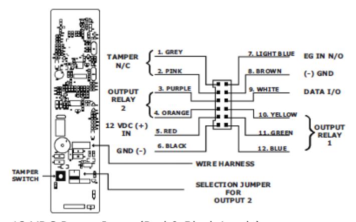
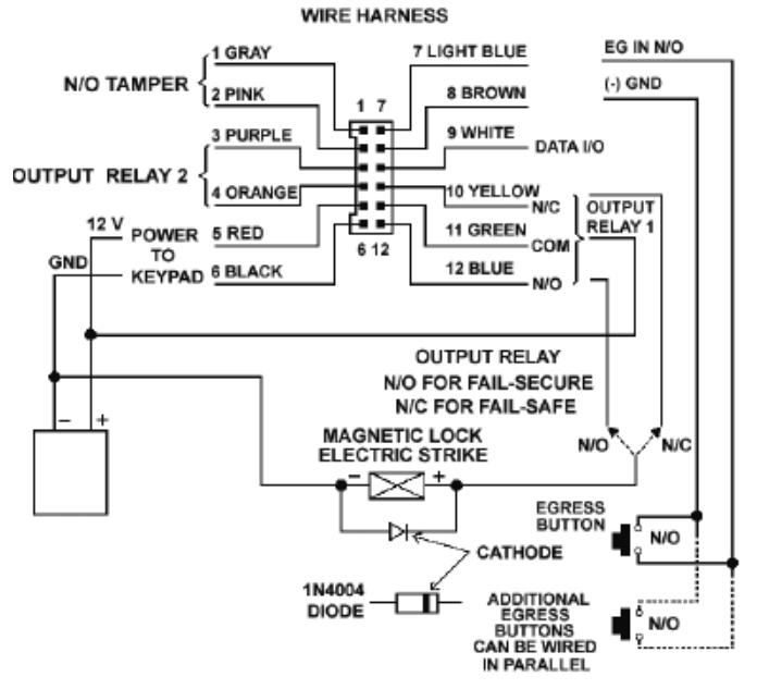
12 VDC Power Input (Red & Black Leads) Connect a 12VDC power supply. Connect with the (+) to the Red lead and the (-) to the Black lead.
Normally-Closed Tamper Switch (Grey & Pink Leads) Connect this N/C terminal to the 24 hour protective zone of an alarm system if necessary. the alarm will sound if the front cover of the KP-300 is removed.
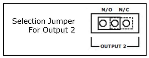
Output Relay 2 (Purple & Orange Leads)
A dry relay contact rated for 1A @ 24 VDC which is jumper selectable is controlled by the PINs/Cards.
EG IN (Egress Input) (Light Blue Lead)
A Normally Open (N/O) input terminal referenced to (-) ground. Connect a Normally Open exit station to activate Output 1.
Exit station is normally located on the interior of the building.
More than one exit station can be connected in parallel to this terminal. Leave this terminal open if not used. See programming Location 90 for more information about the Egress Input.
GND (-) (Common Ground) (Brown Lead)
A common ground point of the keypad. It is common to the black lead.
Output 1 (Output 1 Relay) (Yellow, Green & Blue Leads) 2 Ampere relay, dry contact, controlled by Group 1. Recommended for door strike and magnetic locks. Yellow lead is Normally Closed (N/C), blue lead is Normally Open (N/O), and green lead is the common contact. Use N/C output for Failsafe operation and N/O for Fail-secure operation. The relay is programmable for Latching Mode or Momentary Timing Mode. See programming Location 51 for details.
LED INDICATORS
Yellow Led Monitors Power Input And Key Press. Green Led On When Output 1 Is Active
YELLOW LED INDICATOR AND TONES
| LED SIGNALS | TONES | STATUS | ||
|---|---|---|---|---|
| ON | NONE | IN PROGRAMMING MODE | ||
| 1 FLASH | 1 BEEP | SUCCESSFUL KEY ENTRY | ||
| 2 FLASHES | 2 BEEPS | SUCCESSFUL CODE ENTRY | ||
| 5 FLASHES | 5 BEEPS | FAULTY CODE ENTRY | ||
|
CONTINUOUS
FLASHING |
CONTINUOUS
TONE |
POWER UP DELAY | ||
|
1 FLASH IN
1 SECOND |
NONE | IN STANDBY MODE | ||
|
NONE
1 LONG BEEP |
PIN STORED IN SYSTEM | |||
- − Beeps and Tones can be silenced through Location 71
- − Output Relay activation beep can be selected by Location 72
- − Standby Flashing option can be selected by Location 73
PROGRAMMING INSTRUCTIONS
<u>Set Keypad Into Programming Mode With The Installer Code</u> Important Note:
DO NOT TURN OFF POWER WHEN IN PROGRAMMING MODE
as it may cause data loss or errors in programmed features.
The keypad beeps continuously for approximately one minute after power up.
Wait for the beeping to stop before entering in the Installer Code to access Programming Mode.
Factory set installer code is 0 0 0 0 * * . For security purposes, it is advisable to program a new Installer Code.
2 beeps confirm a valid Installer Code. The Yellow LED is constantly on while in programming mode.
Direct Access To Programming Mode With The "DAP" Code
In the case of a lost Installer Code it is still possible to access the programming mode using the Direct Access to Programming (DAP) code.
- 1. Switch OFF power for 1 minute.
- 2. Switch ON power. The keypad is in power-up mode for approximately 1 minute and there is a continuous beep.
- 3. Create a momentary closure between the Brown and Light Blue wire to enable DAP function (This must be done while in power-up mode).
- 4. Key in 8 0 8 0 ★ ★ . The existing Installer Code is erased and the power-up tone stops. The keypad is now in Programming Mode and is ready for the entry of a new Installer Code.
Refresh Code
The keypad can be refreshed to the factory defaults.
Enter the code 9 9 9 9 # to refresh the keypad. All previously entered data will be erased except for the Installer Code.
DEFAULT KEYPAD VALUE TABLE
| LOCATION | PARAMETERS |
DEFAULT FUNCTION
& VALUES |
|---|---|---|
| 01 | INSTALLER CODE |
0 0 0 0 FACTORY SET
NOT A DEFAULT VALUE |
| 02 | ||
| 03 |
COMMON USER PIN
O/P 1 |
|
| 04 |
COMMON USER PIN
O/P 2 |
|
| 10 |
USER PINS & CARDS
O/P 1 |
|
| 20 |
USER PINS & CARDS
O/P2 |
|
| 40 | VISITOR CODES | |
| 51 | O/P MODE OF O/P 1 |
TIME = 5 SECONDS
MOMENTARY |
| 52 | O/P MODE OF O/P 2 |
TIME = 5 SECONDS
MOMENTARY |
| 60 | SAFETY & LOCKOUT |
CODE=1, 10 FALSE CODES
LOCK OUT 1 MINUTE |
| 70 |
USER CODE ENTRY
MODE |
CODE=2, MANUAL ENTRY
MODE |
| 71 |
TONE ON/OFF
SELECTION |
CODE=1, TONE ON |
| 72 |
O/P OPERATION
ANNOUNCER |
CODE=1, NOTIFICATION
BEEP ON |
| 73 |
STATUS LED
FLASHING |
CODE=1, FLASHING EN
ABLED |
| 94 | OPERATION MODES |
CODE=0, STAND ALONE
KEYPAD |
NOTE: The DAP Code 8 0 8 0 and the Refreshing Code 9 9 9 9 are fixed in the keypad and cannot be changed in any way.
Keypad Programming
Wait until beeping stops (approximately 1 minute after power up) to begin programming.
A total of 1100 User PINs and/or Cards are available - Output 1 (Group 1): 1,000 PINs and/or Cards Output 2 (Group 2): 100 PINs and/or Cards
Set Keypad Into Programming Mode Using The Factory Set Installer Code
Enter 0 0 0 0 * *to enter Programming Mode. Two beeps will indicate successful entry.
Changing The Installer Code
While in Programming Mode enter 0 1 3 2 8 9 # . This will change the Installer Code to "3289" and is used an example of a new Installer Code. Two beeps will indicate successful entry.
Record An EM Card To Operate Output 1
FNTFR 1 0 1 001 READ CARD #
- (a) (b) (c)
- (d)
- (e)
- (a) 10 = Programming location for Output 1
- (b) 1 = Programming option for EM card
- (c) 001 = ID Number. Must be 000 to 999
- (d) READ CARD = Place card within range of the keypad
- (e) # = Confirm card read. 2 beeps indicate successful entry
Set User Pin To Operate Output 1
FNTFR 1 0 2 002 8321
-
(a) (b) (c) (d) (e)
- (a) 10 = Programming location for Output 1
- (b) 2 = Programming option for User PIN
- (c) 002 = ID Number. Must be 000 to 999
- (d) 8321 = The programmed User PIN. "8321" is used as an example.
- (e) # = Confirm entry. 2 beeps indicate successful entry
ENTER 10 3 003 READ CARD 6123 # (a) (b) (c) (d) (e) (f) (a) 10 = Programming location for Output 1 (b) 3 = Programming option for EM card and User PIN (c) 003 = ID Number. Must be 000 to 999 (d) READ CARD = Place card within range of the keypad (e) 6123 = User PIN associated with the EM card. 6123 is used as an example. (f) # = Confirm card read. 2 beeps indicate successful entry Record EM Card & Common User Code To Operate Output 1
Record An EM Card & User PIN To Operate Output 1
ENTER 10 4 004 READ CARD # (a) (b) (c) (d) (e)
- (a) 10 = Programming location for Output 1
- (b) 4 = Programming option for EM card and Common User code
A common user code must be set at programming Location 03 first for this operation mode. The code can
be used for all EM cards in this operation mode.
- (c) 004 = ID Number. Must be 000 to 999
- (d) READ CARD = Place card within range of the keypad
- (e) # = Confirm card read. 2 beeps indicate successful entry. The Common User code is associated with this user automatically.
Close The Programming Mode
Enter * * . 2 beeps indicate that programming mode is closed
OPERATION
Unlock Door With An EM Card READ CARD
A tone will sound and the green LED will illuminate. The door is now unlocked.
Unlock Door With A User Pin Code
ENTER USER PIN 8 3 2 1 #
"8321" for example. A tone will sound and the green LED will illuminate. The door is now unlocked.
Unlock Door With An EM Card & User Pin
READ CARD 8 3 2 1 #
"8321" for example. A tone will sound and the green LED will illuminate. The door is now unlocked.
Unlock Door With An EM Card & Common User Code READ CARD 8 3 2 1 #
"8321" for example. A tone will sound and the green LED will illuminate. The door is now unlocked.
FEATURE PROGRAMMING
The feature values are set and stored using the Programming Locations. Programming can be made continuously and it is not necessary to program in sequence order.
Programming Criteria For Codes
PRIME CODES: PIN, Installer, Duress, Common User and Visitor are all examples of Prime Codes. These codes must be unique in the programming. A Prime Code may not be duplicated for a Secondary Code to work with an EM card or vice versa.
PRIME CARDS: All EM cards are Prime Cards. The cards used for Outputs 1 and 2 must be unique. The card always has priority to be read when working in "EM card & Secondary PIN" or "EM card & Common User PIN" mode.
WARNING FOR A REPEATED USE OF PRIME CODE OR
CARD: One long beep is given if a code/PIN is entered or a card is read if that prime code or card is repeated. This indicates that the code/PIN or card was already entered. The programming is not valid.
SECONDARY USER PINS: The Secondary User PINs are used to enhance security. They are used after a card in "EM card & Secondary User PIN" programming. Secondary Codes can be repeated but they must not be a duplicate of a Prime Code. The keypad will reject a duplicated Prime Code for a Secondary User PIN or vice versa.
ADVANTAGES OF USING SECONDARY USER PINS: The repeated Secondary User PINs can be used as a group Common User code for a group of EM cards thereby simplifying programming.
SECURITY LEVEL COMPARISON OF THE SECONDARY USER PIN/CODE FOLLOWING CARD READING
EM CARD & COMMON USER CODE: All EM cards use the same user code. Security level is better than a card alone since the card bearer will also need to know the code for access.
EM CARD & GROUP USER CODE: EM cards are separated by group. Security level is better than a common code since the card bearer will also need to know the group code for access.
EM CARD & UNIQUE SECOND USER CODE: Each card is associated with a unique user code. Only a person with knowledge of the code can use the card for access.
Make a list of user names and associated codes/ pins/cards and keep it in a secure area.
Program the Installer Code (Location 01)
The Installer Code is the authorization code for entering the Programming Mode. It is not a user code.
The Installer Code must be 4 to 8 digits in length.
There is only one Installer Code. Previous Installer Codes are replaced with the new code.
To set a new Installer Code -
- 1. Set the keypad to Programming Mode
- 2. Enter 01, 4 to 8 digit new code, #
Program the Common User Code/PINs for Output 1 (Location 03) and Output 2 (Location 04)
The Common User Code/PINs 1 and 2 are prepared for operating Outputs 1 and 2 respectively as an enhanced code. The Common User Code/PIN must work in the form of "Card & Common User Code/PIN" to operate the outputs. See Locations 10 and 20 for more information. A Common User PIN alone will not operate the outputs directly.
To set the Common User Code/PIN -
- 1. Set the keypad to Programming Mode
- 2. Enter 03 (or 04), 4 to 8 digit code, #
Record/Delete PINs or Cards for Output 1 & 2
A total of 1100 User PINs and/or Cards are available - Output 1 (Group 1): 1,000 PINs and/or Cards Output 2 (Group 2): 100 PINs and/or Cards
LOCATION MEDIA USER ID CARD/USER PIN SUBMIT 10 or 20 1 to 5 000 to 999 4 to 8 DIGITS #
LOCATION -
10 = Group 1
20 = Group 2
MEDIA -
- 1 = EM Card only
- 2 = PIN only
- 3 = EM Card & Secondary Pin
- 4 = EM Card & Common Pin
- 5 = Delete a PIN/Card from the selected User ID
USER ID -
Group 1: 000-999 Group 2: 001-100
CARD/USER PIN -
- The User PINS are 4 to 8 digits long. Key in the User PIN for each User ID and confirm entry with the # key.
- Place the EM card close to the keypad reader to associate it with an ID and confirm entry with the # key.
- Read the card first and then key in the secondary user PIN to associate it with an ID. Then confirm entry with the # key.
PROGRAMMING AND OPERATION EXAMPLES
EM CARD ONLY -
To program -
Set keypad to Programming Mode and
ENTER 1 0 1 001 READ CARD #
-
(a) (b) (c) (d) (e)
- (a) 10 = Programming location for Output 1
- (b) 1 = Programming option for EM card only
- (c) 001 = ID Number. Must be 000 to 999
- (d) READ CARD = Place card within range of keypad. 1 beep confirms entry
- (e) # = Confirm card read. 2 beeps indicate successful entry
Operation -
While in Operation Mode, place card within range of the reader. 2 beeps confirm the card is read and Output 1 is activated.
DELETE A USER ID - Set keypad to Programming Mode and ENTER 1 0 5 001 #
(a) (b) (c) (d)
- (a) 10 = Programming location for Group 1
- (b) 5 = Programming option deletion
- (c) 001 = ID Number. Must be 000 to 999
- (d) # = Confirm entry. 2 beeps indicate successful entry
DELETE AN EM CARD -
Set keypad to Programming Mode and
ENTER 1 0 5 READ CARD #
-
(a) (b) (c) (d)
- (a) 10 = Programming location for Group 1
- (b) 5 = Programming option deletion
- (c) READ CARD = Put the card within range of the keypad
- (d) # = Confirm card read. 2 beeps indicate successful entry
CLEAR A WHOLE GROUP -
Set keypad to Programming Mode and
ENTER 1 0 0 9 9 9 #
- (a) (b) (c)
- (a) 10 = Programming option for Group 1 (20 for Group 2)
- (b) 5 = Programming option for Group deletion
- (c) # = Confirm entry. 2 beeps indicate successful entry
Visitor Codes (Location 40)
The Visitor Codes are the temporary codes for operating Output 1 only. They can be programmed as one-time codes or time-limited codes. Visitor codes are cleared automatically after expiration.
LOCATION VISITOR ID VISITOR PERIOD VISITOR CODE SUBMIT 40 01 to 50 00 or 01 to 99 4 to 8 Digits #
VISITOR ID - 50 Visitor ID's (01 to 50)
VISITOR PERIOD -
00 = One-time visit. Cleared after one use.
01 to 99 = Time limit in hours from 1 hour to 99 hours. Code is cleared after time expires.
VISITOR CODE -
- The codes are 4 to 8 digits long.
- The Visitor Code must be the same length as the Installer Code for Auto
- Mode code entry.
- Visitor Codes will not reset Duress Output
Note: Visitor Codes are cleared after power down to prevent extension of the Visitor period.
PROGRAMMING EXAMPLES
SET A ONE TIME USE VISITOR CODE - To program -
Set keypad to Programming Mode and
- ENTER 4 0 0 1 00 8321 #
- (a) (b) (c) (d) (e)
- (a) 40 = Programming option for Visitor Code
- (b) 01 = Visitor ID number
- (c) 00 = Programming option for One Time use
- (d) 8321 = The programmed Visitor PIN
- (e) # = Confirm entry. 2 beeps indicate successful entry
SET A TIME LIMIT VISITOR CODE -
To program -
Set keypad to Programming Mode and
ENTER 4 0 0 1 03 8321 #
(a) (b) (c) (d) (e)
- (a) 40 = Programming option for Visitor Code
- (b) 01 = Visitor ID number
- (c) 03 = Programming option in hours. 3 hours in this example
- (d) 8321 = The programmed Visitor PIN
- (e) # = Confirm entry. 2 beeps indicate successful entry
DELETE A VISITOR CODE -
Set keypad to Programming Mode and
ENTER 4 0 0 1 #
- (a) (b) (c)
- (a) 40 = Programming option for Visitor Code
- (b) 01 = Visitor ID number
- (c) # = Confirm entry. 2 beeps indicate successful entry
CLEAR ALL VISITOR CODES -
Set keypad to Programming Mode and
ENTER 4 0 0 9 9 9 #
- (a) (b) (c)
- (a) 40 = Programming option for Visitor Code
- (b) 0999 = Delete all codes from this location command
- (c) # = Confirm entry. 2 beeps indicate successful entry
Configure Output 1 & Output 2 Modes (Location 51, 52)
Two relay outputs are programmable for latching and momentary operation.
LOCATION OUTPUT MODE AND TIME SUBMIT 51 or 52 0 or 1 to 99999 #
LOCATION -
51 = Output 1
52 = Output 2
OUTPUT MODE AND TIME -
0 = Latching Mode. Output is activated with valid entry and is then deactivated with a second valid entry.
1 to 99999 = Momentary Mode. Time in seconds from 1 second to 99999 seconds (default is 5 seconds). Output will remain active for the duration of the programmed time and then automatically deactivate when the time interval expires.
Personal Safety and Keypad Lockout (Location 60)
LOCATION LOCKOUT MODE SUBMIT 60 SEE BELOW FOR CODES #
LOCKOUT MODE CODES -
00 = The Lockout feature is disabled
- 1 = After 10 successive failed entries, keypad locks for 1 minute (default)
- 5 to 10 = After 5 to 10 successive failed entries, keypad locks for 15 minutes
User PIN Entry Mode (Location 70)
LOCATION ENTRY MODE SUBMIT 70 1 or 2 #
ENTRY MODE -
- 1 = Auto Entry Mode. This mode eliminates the need to submit entries with the " # " key. In this mode all user PINs must be the same length as the Installer Code. For example: If the Installer Code is 5 digits, then all user PINs must be 5 digits as well.
- 2 = Manual Entry Mode (default). This mode requires the " # " key to submit entries. In this mode user PINs can be between 4 and 8 digits in length and need not match the length of the Installer Code.
Tone On/Off Selection (Location 71)
This selection allows the sounds (tones/beeps) to be set on or off. Please note that the tones for Warning and Power-Up are always audible.
LOCATION MODE SUBMIT 71 0 or 1 #
MODE -
0 = Silent
1 = Tones/beeps are audible (default)
Output Automation Announcer (Location 72)
The Announcer gives a notification tone to the user on the operation status of the output. There are two modes available. The announcer is off if silent mode is selected in Location 71.
LOCATION MODE SUBMIT 72 0 or 1 #
MODE -
- 0 = 2 beeps are sounded when a valid entry is submitted and an output is activated.
- 1 = 1 second long notification tone is sounded when a valid entry is submitted and an output is activated (default).
Yellow LED Flashing On/Off During Standby (Location 73)
LOCATION MODE SUBMIT 73 0 or 1 #
MODE -
0 = Yellow LED flashes during standby (default)
1 = Standby flashing is disabled
Operation Modes (Location 94)
LOCATION MODE SUBMIT 94 0 #
MODE -
0 = Stand Alone Mode (default). The keypad operates with complete functionality.
APPLICATION EXAMPLE
Note:
- Connect the 1N4004 as close as possible to the lock to absorb back EMF and prevent damage to the keypad. The 1N4004 is not required if the electric lock is AC operated.
- To avoid Electro-Static-Discharge (ESD) from interfering with the operation of the keypad, always ground the (-) terminal of the keypad to earth ground.
APPLICATION HINTS FOR THE AUXILIARY TERMINAL
Output 2: Shunting a N/C Zone
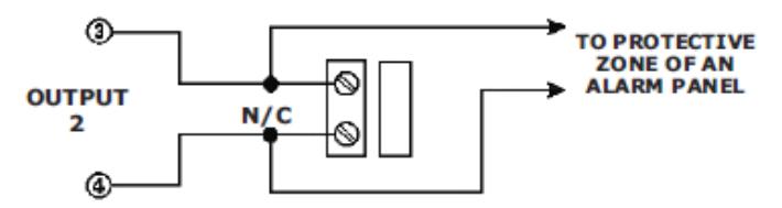
Use a N/O output contact to shunt a N/C protective zone.
Set output contact to Latching Mode (Output Mode = 0) using programming option 52.
Output 2: Alarm System Arming/Disarming
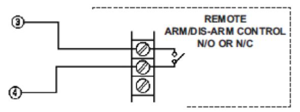
Use the N/O or N/C output contact to make an Arm/ Disarm control of an alarm system.
Consult your alarm control panel manual for the appropriate output contacts to be used for Arm/ Disarm control.
For single station systems, set output contact to Latching Mode (Output Mode = 0) using programming option 52.
For multi-station systems, set output contact to Momentary Mode (Output Mode = 1) using programming option 52.
GLOSSARY
Dry Contact
Dry contacts do not have voltage connected to them. The Relay Output contacts in the keypad are dry contacts.
N/C Contact
The contact is closed in the static state and open in the active state. The contact is open when the circuit is active.
N/O Contact
The contact is open in the static state and closed in the active state. The contact is closed when the circuit is active.
Transistor Open Collector Output
An open collector output is equivalent to a normallyopen, (N/O), contact referring to ground, (-), the same as a relay contact connected to ground, (-). The transistor is normally turned Off, and the output switches to ground, (-), when turned On.
The Duress, Inter-lock and Key Active/Alarm Outputs are open collector outputs and the current is limited to 100 Ma. maximum and 24 VDC maximum.
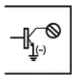
Equivalent
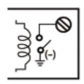
Open Collector Output Output switches to Ground when activated
N/O Contact Output Output switches to Ground when activated
PROGRAMMING SUMMARY CHART
| Default | _ | _ | _ | _ | _ | _ |
|---|---|---|---|---|---|---|
| Factory Default | N/A | N/A | N/A | N/A | N/A | N/A |
| Code Entry | 0 1 Installer Code # | 0 3 Common User PIN 1 # | 0 4 Common User PIN 2 # | 1 0 Code 1 Code 2 Code 3 # | 2 0 Code 1 Code 2 Code 3 # | 4 0 Code 1 Code 2 Code 3 # |
| Entry Limit & Code Options | 4 to 8 Digits | 4 to 8 Digits | 4 to 8 Digits |
Code 1: Media
1- EM Card 2- User PIN 3- EM Card & User PIN 4 - FM Card & Common PIN |
5 - Deletion of PIN
Code 2: User ID Group 1 (10): 000 to 999 Group 2 (20): 001 to 100 Code 3: User PINs/Card 4 to 8 Digits |
Code 1: Visitor ID 01 to 50 Code 2: Visitor Period 00 - One time visit 01 to 99 - Time limit in hours Code 3: Visitor PIN 4 to 8 Digits |
| Parameter | Installer Code | Common User PIN O/P 1 | Common User PIN O/P 2 | User PINs & Cards O/P 1 | User PINs & Cards O/P 2 | Visitor Codes |
| Location | 01 | 03 | 04 |
0
Pa |
07
nge 24 |
40 |
Page 24
PROGRAMMING SUMMARY CHART (Continued)
| Location | n Parameter | Entry Limit & Code Options | Code Entry | Factory Default |
| 51 | Output Mode of O/P 1 |
Output Mode and Time
0 - Latching Mode |
5 1 Output Mode # | 5 Seconds |
| 52 | Output Mode of O/P 2 |
1 - Momentary Mode
1 to 99999 seconds |
5 2 Output Mode # | 5 Seconds |
| 09 | Safety & Lockout |
Lockout Code
00- Lockout disabled 1 - 10 Tries, lockout 1 minute 5 to 10 - 5 to 10 tries, lockout 15 minutes |
6 0 Lockout Code # |
Code =1
10 Tries Lockout 1 minute |
| 70 | User Code Entry Mode |
Entry Mode
1 - Auto Mode 2 - Manual Mode |
7 0 Entry Mode Code # |
Mode = 2
Manual Mode |
| 71 | Tone On/Off Selection | 77 | 7 1 Mode Code # | |
| 72 |
Mode
O/P Operation Announcer 0 - Off 1 - On |
Mode
· 0 - Off 1 - On |
7 2 Mode Code # |
Mode = 1
1 Second Tone |
| 73 | Status LED Flashing | 7 3 Mode Code # | Mode = 1 LED Flashes | |
| 94 | Operation Mode | Code = , Stand Alone Keypad | 940# |
Mode = 0
Keypad Mode |
PROGRAMMING SUMMARY CHART (Continued)
| Result |
ode
M m in ming Syste m Progra |
ming as per Factory
Defaults m All Progra |
Cleared
Users is p of Grou Whole |
e
od M Operational m in Syste |
|---|---|---|---|---|
| Code Entry |
*
* de Co * Master * 0000 w Or Ne |
#
9999 |
#
99 Location 09 |
*
* |
| Function |
will be
Code is Code used to mode me. This is not a ming m code. It w Installer m Factory set Installer m in progra manent syste ed if a ne med. for the first ti set syste m progra chang per |
Set all functions back to factory
e: default values Cod Refresh |
ode.
y M p dela ming m wer-u Access to Progra y in the po Code: Valid onl period. Direct p Da |
e
od M ming m Exit Progra |
|
e
Cod m Syste |
0000 | 9999 |
80
80 |
*
* |
ALARM CONTOLS CORPORATION PRODUCT LINE
U.L. LISTED MAGNETIC LOCKS MAGNETIC LOCK MOUNTING BRACKETS MAGNETIC LOCK DRESS-UP COVERS MAGNETIC LOCK DRILL JIGS SELF-CONTAINED DIGITAL KEYPADS U.L LISTED REQUEST TO EXIT STATIONS EXPLOSION-PROOF REQUEST TO EXIT STATIONS MORTISE CYLINDER STATIONS VANDAL RESISTANT REQUEST TO EXIT STATIONS REQUEST TO EXIT STATIONS WITH BUILT-IN TIME DELAY RELAYS AND RELAY BASES TIME DELAY MODULES AUDIBLE INDICATORS DELAYED EGRESS STATIONS CONTROL PANELS EMERGENCY DOOR RELEASES PUSH PLATES ZONE ANNUNCIATORS GRAPHIC ANNUNCIATORS CUSTOM PLATES
LIFE TIME PRODUCT WARRANTY