Aiphone TD-HB Series Selective Call Intercom Installation & Opreation Manual
Open the original PDF document
View PDF

TD-H Series SELECTIVE CALL INTERCOM
TD-1H/B (1-call)
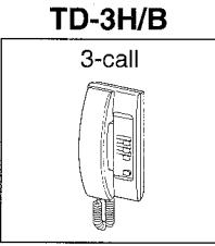
TD-3H/B (3-call)
Models: TD-6H/B (6-call)
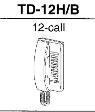
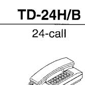
TD-12H/B (12-call) TD-24H/B (24-call)
INSTALLATION & OPERATION MANUAL
CONTENTS
| 1 | SYSTEM OUTLINE & COMPONENTS | 1 |
|---|---|---|
| 2 | NAMES & FEATURES | 2 |
| 3 | PRECAUTIONS ON INSTALLATION & WIRING | 3 |
| 4 | WIRING | 4 ~ 9 |
| 5 | MOUNTING | 10 |
| 6 | OPERATIONS on TD-H | 11 |
| 7 | CLEANING THE EQUIPMENT | 12 |
| 8 | TECHNICAL PRECAUTIONS | 12 |
| 9 | SPECIFICATIONS | 12 |
SYSTEM OUTLINE & COMPONENTS
■ System outline
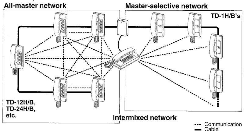
TD-H/B is a multi-channel selective-call intercom. On loop-wiring, five TD-H station models, intermixable, can be configured to all-master, master-selective system or mixed. Additionally, using a potential station(s), PanTilt MY and/or audio IE/IF door stations (2 max.) and paging zone(s) may be incorporated.
■ Package contents
- TD-H phone station
- Packet of screws
- Installation & Operation Manual
Components available
Intercom master stations: Intermixable
TD-1H/B 1-call sub
TDW-1~24/A
TD-6H/B 6-call
PS-12A or PS-12C Power supply
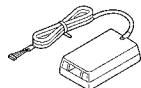
Terminal box with 1.5m, 5 feet cord for connecting TD-nH for desktop use. or surface wall mounting.
■ Optional accessories
DE-UR
Door station adapter
IF-DA
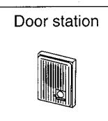
IE/IF Series IE-JA, IE-NC, IE-DC, etc.
MY-DC/A

MY Series MY-DG/A, MY-EA MY-FA, MY-CA, etc.
MY-CU
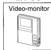
MYH-CU Sub-monitor
PD-2
PD-1. no talkback
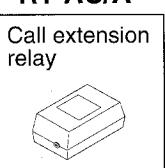
RY-AC/A
2 NAMES & FEATURES
Names & functions
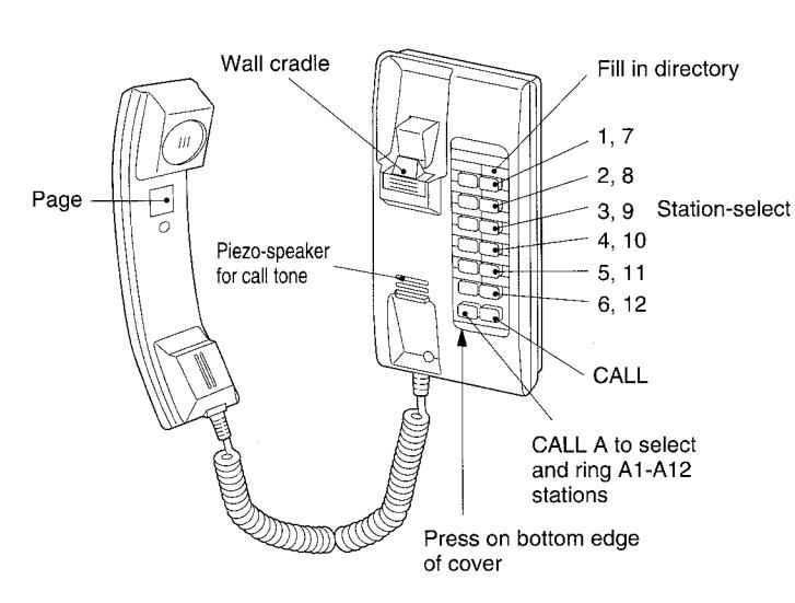
TD-24H/B
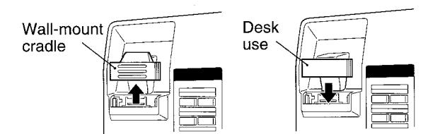
Handset cradle
Reversely attach wall-mount cradle for desk use.
Cable clamp
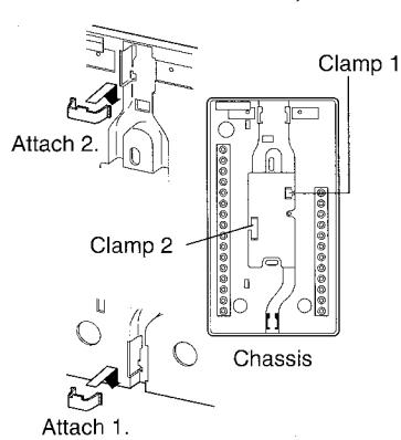
Two cable clamps (parts) are included on every TD-nH chassis. See page 10.
Directory card
For TD-24H/B, fill in names on 2 lines, aligning with the right sample.
■ Features
- Intercom communication among 25 stations (max.) in all-master configuration. Single-master system, with TD-1H/B station, or intermixed.
- Intermixable five TD-H station models in a system
- Multiple talk paths for intercom (and paging)
- Station-select break-in call
- Max. 28 conductor cable, station to station
- PanTilt video or audio door station (2 per system)
- Incorporates a zone(s) for paging (with talkback)
- Call extension buzzer or light
| AIPHONE | : TD-24H |
|---|---|
| President | |
| A Conf. 1 | A |
| 1 | 7 |
| Reception | ] |
| A Conf. 2 | A |
| 2 | 8 ( |
| Α | A |
| 3 | 9 |
| A | A |
| 4 | )()10 |
| Δ | Α. |
| A | A |
| 5 | 11 |
| A | A |
| 6 | 12 |
| CALL A | CALL |
| ) | |
PRECAUTIONS ON INSTALLATION & WIRING
CAUTION
- ★ Do not connect any terminal on any unit to AC power lines to prevent fire or unit damage.
- ★ Do not install more than one power supplies PS-12A (or PS-12C) for an entire TD-H system, including adaptors for door station and/or paging.
- ★ Do not attempt to install or connect wires on TD-H equipment while system's power supply is plugged in.
- ★ TD-H masters and related equipment, except door station, are designed for indoor use only. Do not install outdoors.
- ★ Do not connect any other power source than specified on terminals +, -. Doing so can damage the TD-H equipment.
IMPORTANT
- ★ For system's installation, there is no need to disassemble the equipment. Do not open any TD-H system components unless properly qualified.
- ★ Any other manufacturer's products installed with this system (power supply, external signalling device, etc.) are not covered under Aiphone's warranty.
-
★ Do not mount TD-H equipment in the following places, as it may cause the system to malfunction:
- High or extreme cold temperature areas: under direct sunlight, near equipment that varies in temperature, in front of air-conditioner, inside a refrigerated area, etc.
- Places subject to moisture or humidity extremes.
- Places subject to environmental conditions, such as dust, oil, chemicals, etc.
- ★ TD-H is an electrical device, which must not be subjected to water, or any other liquid.
- ★ Weather conditions, such as lightning storms, may cause damage to TD-H equipment. We recommend that power surge protection be installed as follows: (However, this does not guarantee that no damage will occur).
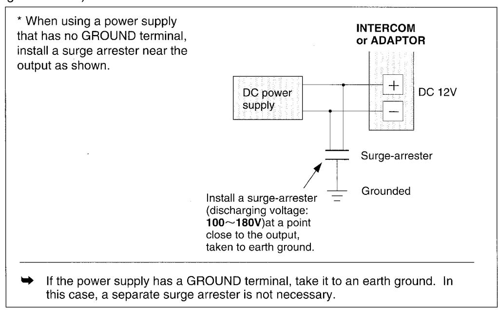
Before actually installing the TD-H system, the contents on pages 4 ~ 10 must be thoroughly read and understood.
WIRING
All-master system configurations
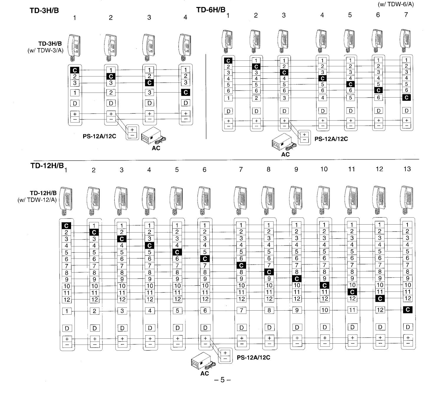
TD-H is basically designed for making all-master system on looped trunk cable, as per table below:
| Models | Station capacity | Cable required (*) |
|---|---|---|
| TD-3H/B | 4 stations | 7-conductor cable |
| TD-6H/B | 7 stations | 10-conductor cable |
| TD-12H/B | 13 stations | 16-conductor cable |
| TD-24H/B | 25 stations | 28-conductor cable |
(*) Includes a conductor for D terminal required for a DE-UR(s)
TD-1H/B, 1-call sub providesTD-3H/B ~ 24H/B all-master network with own communication points (intermixed system).
■ Cable requirements
Use multiconductor cable (non-twisted), 0.65 ~ 0.8mm dia., 22~ 20AWG, to accommodate maximum number of intercom stations, and featured audio or PanTilt video door station(s) and/or page to a zone(s), each of which uses one potential wire.
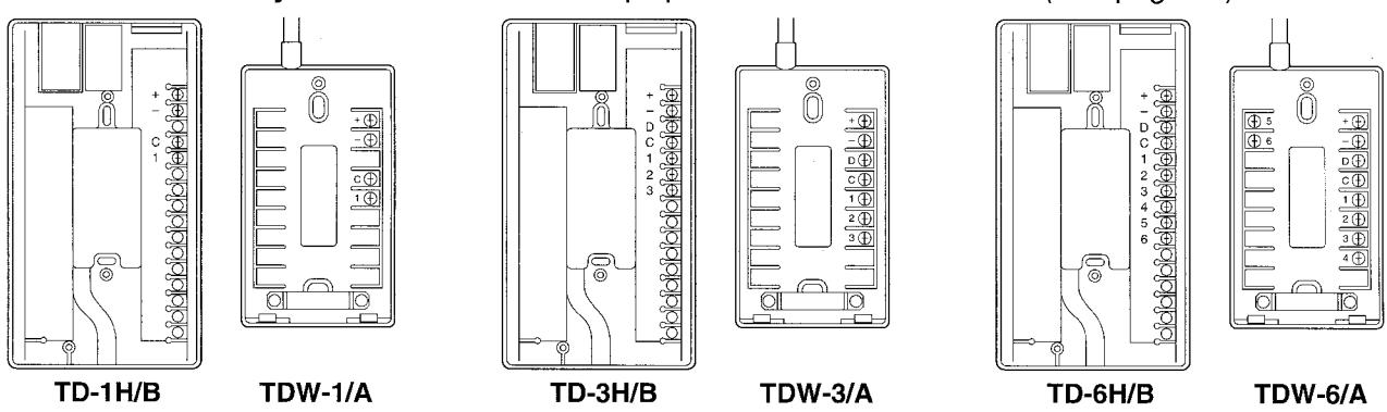
■ Terminal - block layout ★ Two cable clamp tips are attached on chassis. (See page 10)
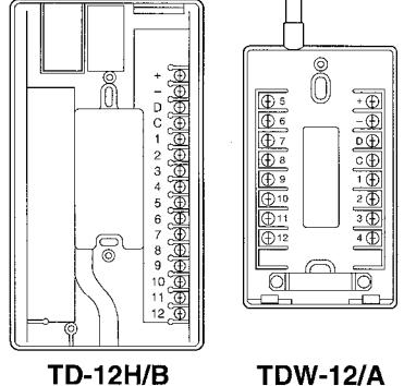
TDW-12/A
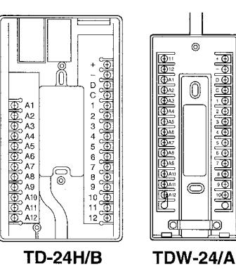
Meaning of terminal symbols
No. 1 ~ 24 are selective station points, providing selective calling and communication for masterto-master communication.
C terminal is a call tone signal receive terminal.
D terminal is a door station call tone line.
+, - terminals are 12V DC power supply lines.
Power supply
Entire TD-H intercoms can be powered by a single PS-12A(12C) power supply, and locate it in the center of the trunk cable. It can also power directly such adaptors as DE-UR, PD-1 & PD-2, which must be all located within 5m, 16' distance from PS-12A(12C).
■ TD-H single-master system
TD-3H/B ~ TD-24H/B makes a single-master network, using TD-1H/B 1-call station to call the master station. TD-1H/B with CALL button only, is allowed to call TD-H master station only.
■ TD-H all-master system
TD-H all-master system can be made by running parallel conductors from station to station. No. of conductors required is: 2 common (or 3 with D line) plus number of TD-H stations installed. As shown, one more TD-H station (the last #) may be added on each own No. button. TD-6H/B
■ TD-H all-master system
TD-24H/B
| 1 | 2 | 3 | 4 | 5 | 6 | 7 | 8 | 9 | 10 | 11 | 12 | ||
|---|---|---|---|---|---|---|---|---|---|---|---|---|---|
| TD-24H/ | B (w/TD) | W-24/A) | |||||||||||
| Newstern | (Constant) | (Seewall) | Beneficial | SARBARAÑ | (Mannana) | (Sensorial) | SETTERAL | . Secure 1 | (INTERPRETATION OF THE PARTY OF THE PARTY OF THE PARTY OF THE PARTY OF THE PARTY OF THE PARTY OF THE PARTY OF THE PARTY OF THE PARTY OF THE PARTY OF THE PARTY OF THE PARTY OF THE PARTY OF THE PARTY OF THE PARTY OF THE PARTY OF THE PARTY OF THE PARTY OF THE PARTY OF THE PARTY OF THE PARTY OF THE PARTY OF THE PARTY OF THE PARTY OF THE PARTY OF THE PARTY OF THE PARTY OF THE PARTY OF THE PARTY OF THE PARTY OF THE PARTY OF THE PARTY OF THE PARTY OF THE PARTY OF THE PARTY OF THE PARTY OF THE PARTY OF THE PARTY OF THE PARTY OF THE PARTY OF THE PARTY OF THE PARTY OF THE PARTY OF THE PARTY OF THE PARTY OF THE PARTY OF THE PARTY OF THE PARTY OF THE PARTY OF THE PARTY OF THE PARTY OF THE PARTY OF THE PARTY OF THE PARTY OF THE PARTY OF THE PARTY OF THE PARTY OF THE PARTY OF THE PARTY OF THE PARTY OF THE PARTY OF THE PARTY OF THE PARTY OF THE PARTY OF THE PARTY OF THE PARTY OF THE PARTY OF THE PARTY OF THE PARTY OF THE PARTY OF THE PARTY OF THE PARTY OF THE PARTY OF THE PARTY OF THE PARTY OF THE PARTY OF THE PARTY OF THE PARTY OF THE PARTY OF THE PARTY OF THE PARTY OF THE PARTY OF THE PARTY OF THE PARTY OF THE PARTY OF THE PARTY OF THE PARTY OF THE PARTY OF THE PARTY OF THE PARTY OF THE PARTY OF THE PARTY OF THE PARTY OF THE PARTY OF THE PARTY OF THE PARTY OF THE PARTY OF THE PARTY OF THE PARTY OF THE PARTY OF THE PARTY OF THE PARTY OF THE PARTY OF THE PARTY OF THE PARTY OF THE PARTY OF THE PARTY OF THE PARTY OF THE PARTY OF THE PARTY OF THE PARTY OF THE PARTY OF THE PARTY OF THE PARTY OF THE PARTY OF THE PARTY OF THE PARTY OF THE PARTY OF THE PARTY OF THE PARTY OF THE PARTY OF THE PARTY OF THE PARTY OF THE PARTY OF THE PARTY OF THE PARTY OF THE PARTY OF THE PARTY OF THE PARTY OF THE PARTY OF THE PARTY OF THE PARTY OF THE PARTY OF THE PARTY OF THE PARTY OF THE PARTY OF THE PARTY OF THE PARTY OF THE PARTY OF THE PARTY OF THE PARTY OF THE PARTY OF THE PARTY OF THE PARTY OF THE PARTY OF THE PARTY OF THE PARTY OF THE PARTY OF THE PARTY OF THE PARTY OF THE PARTY OF THE PARTY OF THE PARTY OF THE PARTY OF THE PARTY OF THE PARTY OF | (NEWHER) | |||
| CALL |
2
3 4 5 6 7 8 9 10 11 12 |
1 C 3 4 5 6 7 8 9 1 10 11 12 D |
1
2 C 4 5 6 7 8 9 10 11 12 |
1 2 3 C 5 6 7 8 9 10 11 12 D |
1
2 3 4 6 7 8 9 9 10 |
1
2 3 4 5 6 7 8 9 10 11 12 |
1
2 3 4 5 6 C 8 9 10 11 12 |
1
2 3 4 5 6 7 C 9 10 11 12 |
1
2 3 4 5 6 7 8 C |
1
2 3 4 5 6 6 7 8 9 C |
1
2 3 4 5 6 6 7 8 9 10 C |
1
2 3 4 5 6 7 8 9 10 |
|
| CALL A | + | + | + - | + - | + - |
+
- |
D + - | D + | D + - |
+
- |
D + - |
+
- |
PS-12A AC |
|
A1
A2 A3 A4 A5 A6 A7 A8 A9 A10 A11 A12 |
A1
A2 A3 A4 A5 A6 A7 A8 A9 A10 A11 A12 |
A1
A2 A3 A4 A5 A6 A7 A8 A9 A10 A11 A12 |
A1
A2 A3 A4 A5 A6 A7 A8 A9 A10 A11 A12 |
A1
A2 A3 A4 A5 A6 A7 A8 A9 A10 A11 A12 |
A1
A2 A3 A4 A5 A6 A7 A8 A9 A10 A11 A12 |
A1
A2 A3 A4 A5 A6 A7 A8 A9 A10 A11 A12 |
A1
A2 A3 A4 A5 A6 A7 A8 A9 A10 A11 A12 |
A1
A2 A3 A4 A5 A6 A7 A8 A9 A10 A11 A12 |
A1
A2 A3 A4 A5 A6 A7 A8 A9 A10 A11 A12 |
A1
A2 A3 A4 A5 A6 A7 A8 A9 A10 A11 A12 |
/12C |
■ TD-H intermixed system
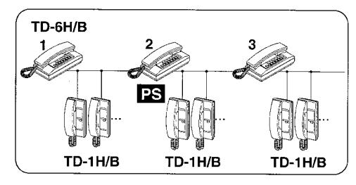
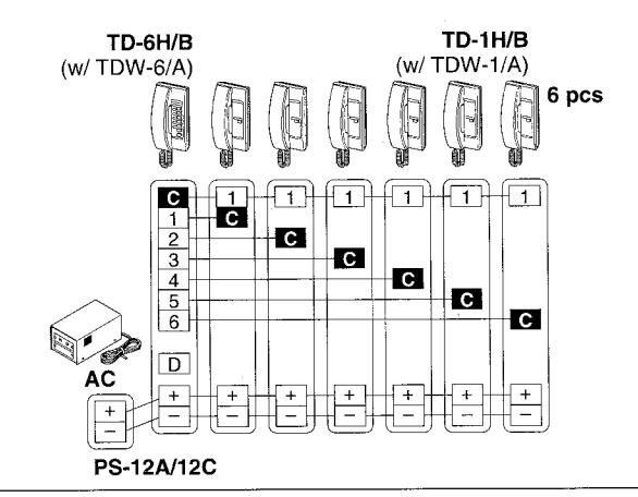
Intermixed system is an all-master & single-master combined within a system. Each TD-H master station may have additio-
nal contacts with TD-1H/B, 1-call station (s).
TD-1H/B stations can be wired to the TD-6H/B master station, using unused conductors in the trunk cable
TD-6H/B (w/ TDW-6/A) TD-1H/B TD-1H/B TD-1H/B х3 С 1 1 3 4 C 1 1 1 2 C 3 1 С C 4 5 6 С 5 С 5 С С С 6 С С 1 2 3 D D D PS-12A/12C
Cable requirements Wiring distance
Use a multi-conductor (non-twisted) cable mm dia., AWG for TD-H intercoms. TD-H intercoms (any communication)
| , | |||
|---|---|---|---|
| Diameter | 0.65mm | 0.8mm | 1.0mm |
| Distance | 650m | 1,000m | 1,500m |
| AWG | 22AWG | 20AWG | 18AWG |
|---|---|---|---|
| Distance | 2,000' | 3,000' | 4,900' |
| 13 | 14 | 15 | 16 | 17 | 18 | 19 | 20 | 21 | 22 | 23 | 24 | 25 |
|---|---|---|---|---|---|---|---|---|---|---|---|---|
|
TD-24H/B |
1 2 | 1 2 | 1 2 | 1 2 | 1 2 | 1 2 | 1 2 | 1 2 | 1 2 | 1 2 | 1 2 | 1 2 |
|
3
4 5 6 7 8 9 10 11 12 |
3
4 5 6 7 8 9 10 11 12 |
3
4 5 6 7 8 9 10 |
3
4 5 6 7 8 9 10 11 12 |
3
4 5 6 7 8 9 10 11 12 |
3
4 5 6 7 8 9 10 11 12 |
3
4 5 6 7 8 9 10 11 12 |
3
4 5 6 7 8 9 10 11 12 |
3
4 5 6 7 8 9 10 11 12 |
3
4 5 6 7 8 9 10 11 12 |
3
4 5 6 7 8 9 10 11 12 |
3
4 5 6 7 8 9 9 10 |
3
4 5 6 7 8 9 10 -11 12 |
|
D + - |
D + - | D + - | D + - | D + - | D + - | D + | D + - | D + - | D + - | D + - | D + - | D + - |
|
A2
A3 A4 A5 A6 A7 A8 A9 A10 A11 A12 |
A1
C A3 A4 A5 A6 A7 A8 A9 A10 A11 A12 |
A1
A2 C A4 A5 A6 A7 A8 A9 A10 A11 A12 |
A1
A2 A3 C A5 A6 A7 A8 A9 A10 A11 A12 |
A1
A2 A3 A4 C A6 A7 A8 A9 A10 A11 A12 |
A1
A2 A3 A4 A5 C A7 A8 A9 A10 A11 A12 A6 |
A1
A2 A3 A4 A5 A6 C A8 A9 A10 A11 A12 A7 |
A1
A2 A3 A4 A5 A6 A7 C A9 A10 A11 A12 A8 |
A1
A2 A3 A4 A5 A6 A7 A8 C A10 A11 A12 A9 |
A1
A2 A3 A4 A5 A6 A7 A8 A9 C |
A1
A2 A3 A4 A5 A6 A7 A8 A9 A10 C |
A1
A2 A3 A4 A5 A6 A7 A8 A9 A10 A11 C |
A1
A2 A3 A4 A5 A6 A7 A8 A9 A10 A11 A12 |
■ Audio door station IE/IF series
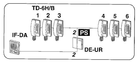
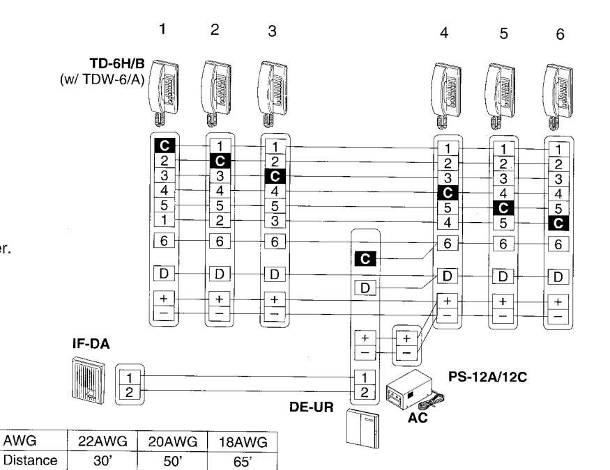
TD-H system may have one or two audio door station IE/IF series, using a potential station. Intermittent tremolo rings at max. 12 TD-H phones. For 2nd door station, change SW. to B position on DE-UR, to change call tone faster.
• From DE-UR to IF-DA, etc.
| Diameter | 0.65mm | 0.8mm | 1.0mm |
|---|---|---|---|
| Distance | 150m | 230m | 350m |
| AWG | 22AWG | 20AWG | 18AWG |
| Distance | 500' | 700' | 1,100' |
• From DE-UR to power supply
| Diameter | 0.65mm | 0.8mm | 1.0mm |
|---|---|---|---|
| Distance | 10m | 15m | 20m |
■ PanTilt video integration to TD-H
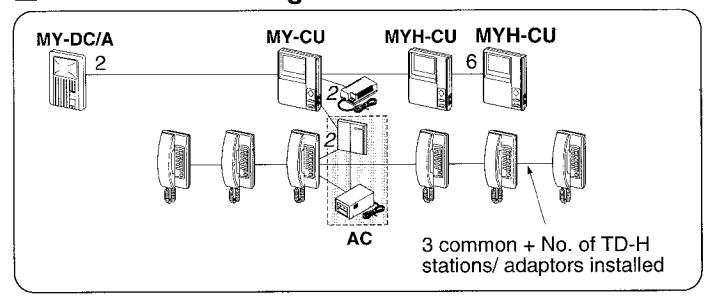
When MY-DC/A calls in, TD-6H/B stations receive an intermittent call tone, with an image on video-monitors. Pick up and select the assigned # station to reply.
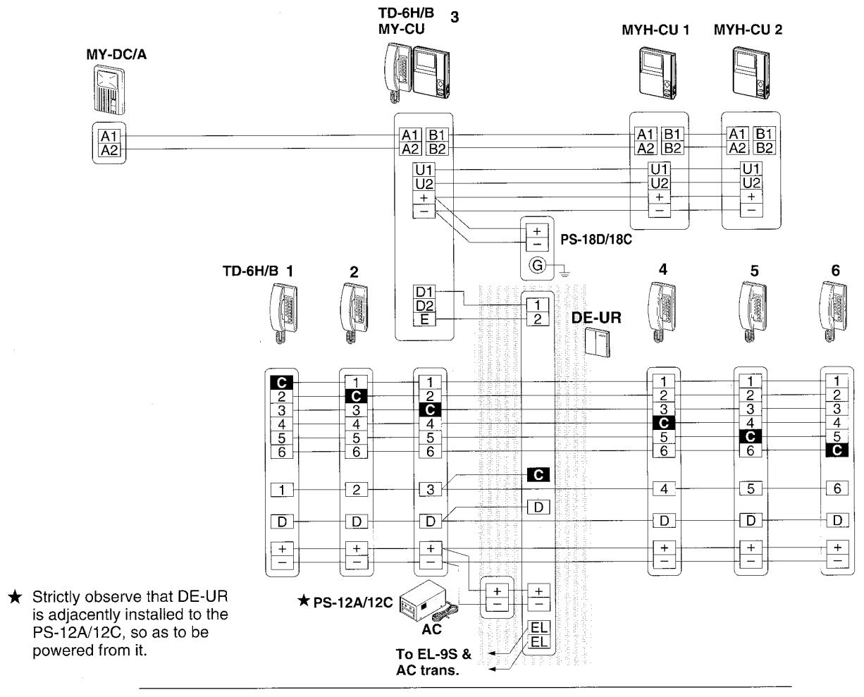
MY-CU cable requirements & power supply
2 conductors (non-twisted) from MY-CU to MY-DC/A. 6 conductors (non-twisted) from MY-CU to MYH-CU submonitors with no extra conductors in the cable.
Wiring distance
• From MY-CU to power supply • From MY-CU to PanTilt door MY-DC/A
| • | |
|---|---|
| Diameter | 1.0mm |
| Distance | 5m |
| AWG | 18AWG |
| Distance | 16' |
| Diameter | 0.65mm | 0.8mm | 1.0mm |
|---|---|---|---|
| Distance | 50m | 65m | 100m |
| AWG | 22AWG | 20AWG | 18AWG |
| Distance | . 165' | 210' | 330' |
· Between TD-H intercoms (any pair)
| Diameter | 0.65mm | 0.8mm | 1.0mm |
|---|---|---|---|
| Distance | 650m | 1,000m | 1,500m |
| AWG | 22AWG | 20AWG | 18AWG |
| Distance | 2,000' | 3,000' | 4,900' |
· From DE-UR to power supply
| Diameter | 0.65mm | 0.8mm | 1.0mm |
|---|---|---|---|
| Distance | 10m | 15m | 20m |
| AWG | 22AWG | 20AWG | 18AWG |
| Distance | 30' | 50' | 65' |
• From MY-CU to MYH-CU #1 (2 monitors)
| Diameter | 0.65mm | 0.8mm | 1.0mm |
|---|---|---|---|
| Distance | 35m | 50m | 75m |
| AWG | 22AWG | 20AWG | 18AWG |
| Distance | 115' | 150' | 250' |
• From MY-CU to MYH-CU #2 (3 monitors)
| Diameter | 0.65mm | 0.8mm | 1.0mm |
|---|---|---|---|
| Distance | 20m | 30m | 50m |
| AWG | 22AWG | 20AWG | 18AWG |
| Distance | 65' | 100' | 150' |
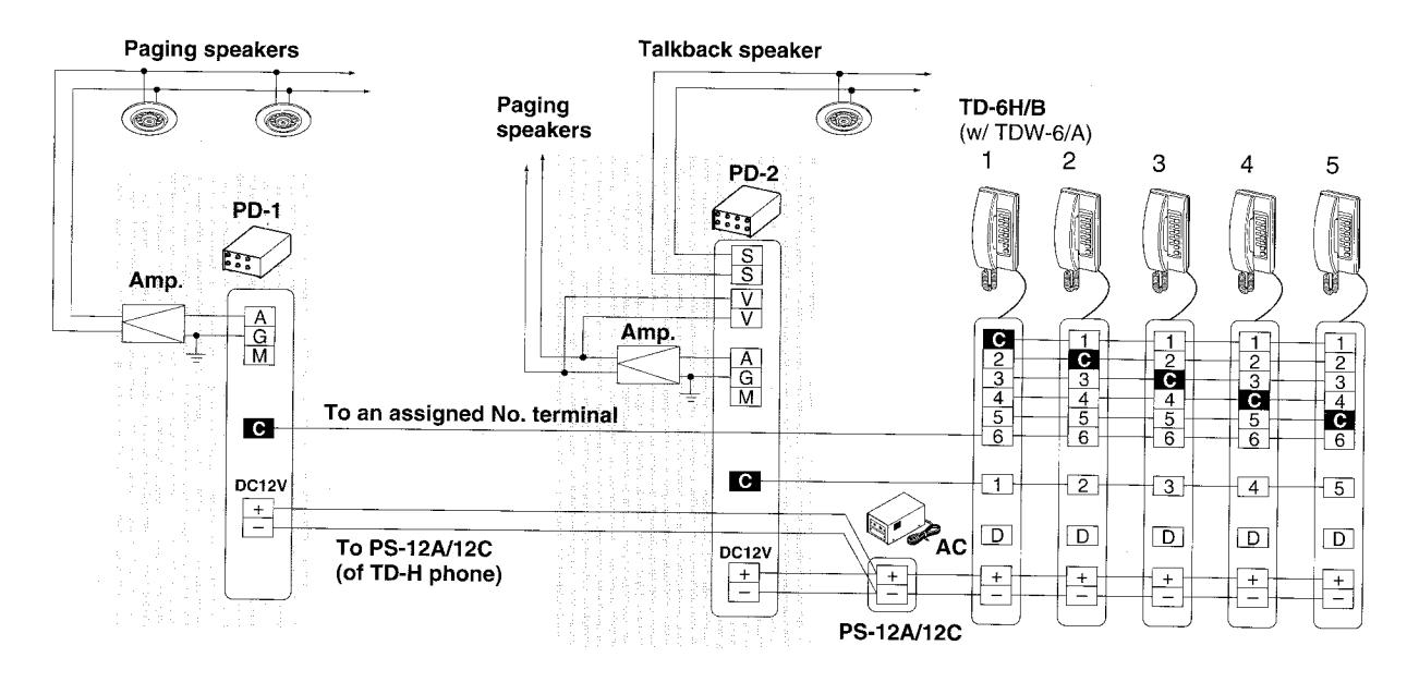
Paging adaptors PD-1 and PD-2
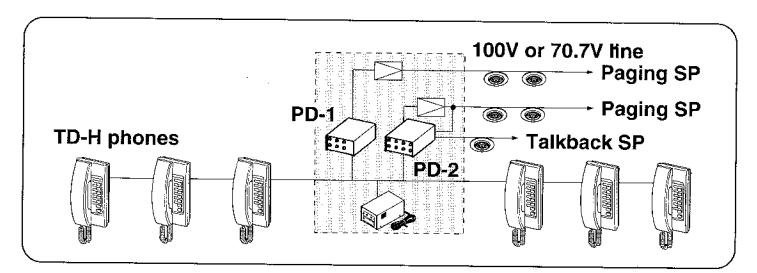
- PD-1 or PD-2 controls each paging zone, using an amp. & paging speakers.
- Multiple paging zones and channels.
- One PD-2 for paging with talkback.
- Must be powered by TD-H's power supply PS-12A/12C.
- Use paging speakers SP-3NA (SP-5N in USA).
- Connection to background music source.
• PD-1 paging adaptor
• PD-2 paging adaptor w/ talkback
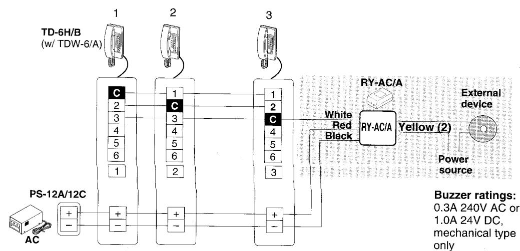
■ Call extension relay RY-AC/A
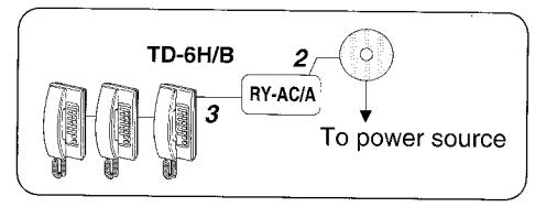
RY-AC/A will activate when station #3 receives a call from a handset station. It lasts as long as that TD-H station is ringing.
5 MOUNTING
- ★ Make sure PS-12A/12C is unplugged while making wiring connections.
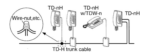
- ★ When drawing out a TD-H station's wires from trunk cable, connect each junction with secured insulation. Or use TDW-n terminal box, allowing plug-in to TD-nH on 1.5m cord end.
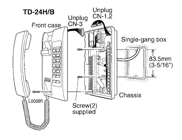
■ TD-nH wall-mounting (on gang box)
- 1. Loosen a front bottom screw.
- Lift the front case off the chassis, and unplug CN1 ~ 3 connectors (varies by model) to disconnect intercom
- 3. Mount the chassis to single-gang box with 2 screws supplied.
- 4. Make wire termination on each screw terminal inside the chassis.
- 5. Plug in CN connectors back to each socket.
- Remount front case to chassis, fastening bottom screw.
- ★ Put together the connector leads to avoid pinching by hook knob or front case.
CN connectors: CN-1 on TD-1H/B, 3H/B CN-1 , 2 on TD-6H/B, 12H/B CN-1 ~ 3 on TD-24H/B
■ TD-nH desk or surface wall mounting
Use TDW-n box for either desk-top or surface wall mounting.
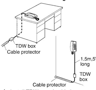
★ Install TDW-n and cable in non-trapping manner.
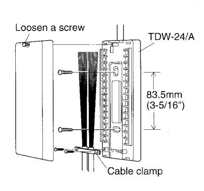
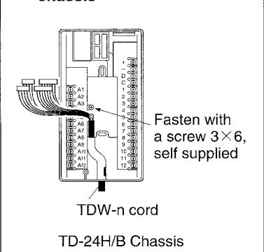
★ Anchor TDW-n cord on the chassis
★ Fasten TDW-n cord or station cable with a clamp (Cut off the parts from TD-1~12H/B chassis).
Connecting TDW-n to TD-nH
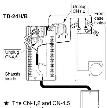
The CN-1,2 and CN-4,5 connectors, becoming, inutilized, should be folded neatly, and not be cut off.
TDW-24/A box
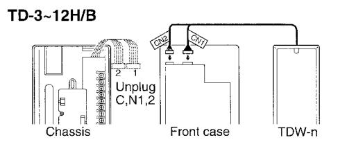
CN2: TD-6H/B & TD-12H/B only
6 OPERATIONS on TD-H -
Station # button selects a TD-H intercom, a zone for page, or a door station.
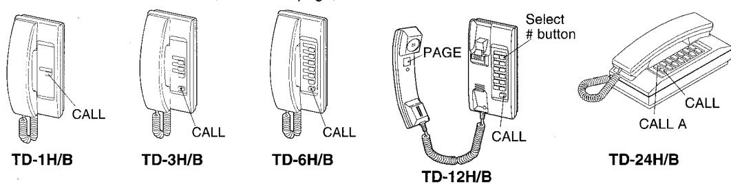
Basic operations
• Calling other TD-H
TREMOLO
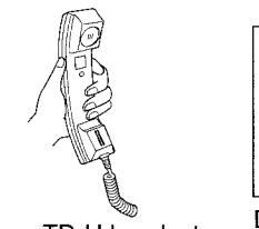
Pick up TD-H handset.
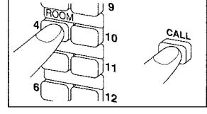
Depress to lock a stationselect button and press CALL button momentarily.
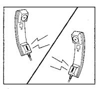
The TD-H station rings tremolo tone. Pick up handset to reply.
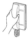
on rings Communicate with handset Pick up on both stations. After communication, both stations hang up.
- ★ On TD-24H/B, depress CALL A to call A1~A12 stations.
- ★ If handset is not replaced, that station will not ring.
- Receiving a call from TD-H When tremolo tone rings on your TD-H station, simply pick up to reply.
■ To talk with a door station
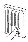
Call button is depressed.
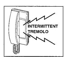
Tremolo tone rings for approx. 2.5 seconds.
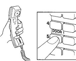
Pick up the TD-H handset. Depress to lock a doorassigned # button.
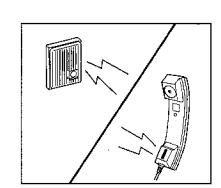
Reply to door station.
Zone page
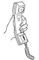
Pick up handset.
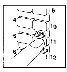
Depress to lock a zoneassigned # button.
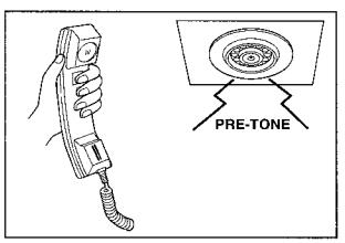
Depress PAGE button inside handset. Pre-tone notifies through zone's speakers
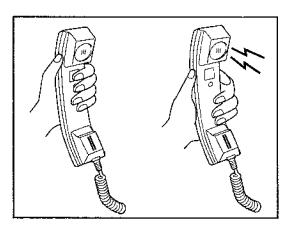
Page while holding down PAGE button. Release PAGE button to receive talkback reply. (with PD-2 only)
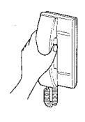
Hang up handset.
Call extension buzzer
Using the RY-AC/A relay, a call from another TD-H or door station activates a separate buzzer (not supplied by Aiphone) while the TD-H station is ringing. Pick up (and select the door) on the TD-H station.
Multiple talk paths are available for intercom and paging
★ If you hear someone speaking after depressing a TD-H station's # button, the station is busy. Hang up and call later.
Filling in directory
On directory strip, fill in names of other TD-H stations, and door / page zone #'s. Push on bottom of directory cover.
CLEANING THE EQUIPMENT
- 1. Clean intercom unit surface with a soft and dry cloth.
- 2. When the soil is not easily cleaned, the cloth may be dampened with neutral household cleanser. Never use an abrasive cleaner or cloth.
TECHNICAL PRECAUTIONS -
Door-assigned # button
★ It is suggested, on TD-24H/B to assign a number button 1~12 for door station(s) or paging zone(s), so they can be addressed by depressing only the station # button. Do not use A1~A12.
Station select break-in call
TD-H allows any station(s) to join on the conversation by station selection.
Paging
★ Do not select and page to more than one zone simultaneously.
SPECIFICATIONS
| Power source | DC 12V. Max. 70mA per station. Use PS-12A or PS-12C power supply for a system. | ||
|---|---|---|---|
| Calling | Station-select button 1 ~ 12 and Call button, rings with tremolo tone. Rings while Call button is held down. (On TD-24H/B, 1 ~ 12 and Call A button rings A1 ~ A12 stations) | ||
| Communication | Multi-talk path, simultaneous intercom. When called by tremolo from other station, pick up the handset. | ||
| Added feature counts as a | a station, assigning a select # button (any) on TD-H station(s). | ||
| Door station | Max. 2 door stations IE/IF Series or PanTilt video, using DE-UR for each. Rings max. 12 TD-H stations with intermittent tremoto, 2.5 sectimed. ★ Call tone selector A or B on DE-UR for 2 doors. | ||
| Zone page | Multiple zones , using a PD-1 or PD-2 (w/talkback), amplifier and an appropriate number of speakers for each. | ||
| Wiring | TD-1H/B TD-3H/B TD-6H/B TD-12H/B TD-24H/B 4 cond. 7 cond. 10 cond. 16 cond. 28 cond. 3 wires common + 1 for each selective calling | ||
| Wiring distance | 650m with 0.65mm diameter. 2,000' with 22AWG. | ||
|
Dimensions
TD-nH/B (n=1,3,6,12) TD-24H/B |
210mm high x 100mm wide x 73mm deep. 8-1/4"H x 3-15/16"W x 2-7/8"D Same, except 83mm, 3-1/4" deep | ||
| Weight | TD-1H/B 410g (0.90 lbs.) TD-3H/B 430g (0.95 lbs.) TD-6H/B 440g (0.97 lbs.) TD-12H/B 460g (1.01 lbs.) TD-24H/B 520g (1.14 lbs.) | ||
**************************************
. ************************************
Printed in Hong Kong (E)