Aiphone TC-M Series International Telephone System Instructions
Open the original PDF document
View PDF

TC-M Series
INTERNAL-TELEPHONE SYSTEM
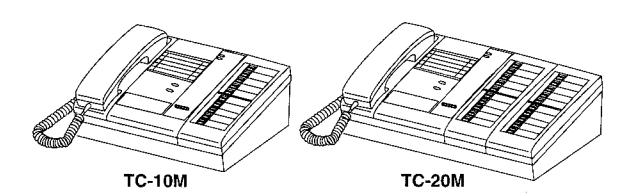
Models: TC-10M: 10-call master TC-20M: 20-call master
INSTALLATION & OPERATION MANUAL
This Manual and the Markings on the product contain various symbols in order that the product can be used safely and properly. and that the installer and user are protected from injury and property damage. The following precautions must be thoroughly read and understood before proceeding.
PRECAUTIONS ON INSTALLATION & WIRING

WARNING Negligence could result in death or serious injury.

CAUTION Negligence could result in injury or damage to property.

\ WARNING
- 1. Do not connect any power source other than specified on TC-M master. Fire or damage to the unit could result.
- 2. Do not open TC-M master. High voltage is present inside, and it can cause electric shock.
- 3. Do not change or alter TC-M master. It can cause fire or electric shock.
- 4. Make sure wires are connected properly before plugging in power supply.
- 5. Keep TC-M master away from water or any other liquid.
- Fire or electric shock could result. 6. Keep AC plug away from moisture or dust.
- 7. Keep AC cord away from being marred or crushed. 8. Do not plug or unplug with wet hands. 9. Do not put any metal into TC-M through openings. It can cause fire, electric shock or unit damage.
✓!\ CAUTION
- 1. Do not make call tone testing with hook switch manually held down. The call tone sounds very loud near your ears, and can cause your hearing damage.
- Do not install or make any wire terminations while power supply is plugged in. It can cause electrical shock or damage to the unit.
- 3. Install TC-M master in a convenient location, but not where it could be bumped or jarred.
- In case of electrical storms, unplug power supply from AC outlet. It can cause fire, electric shock, or power surge damage.
- 5. Do not install TC-M components in any of the following locations, as it may cause the system to malfunction:
- High or extreme cold temperature area:
under direct sunlight, near equipment that varies in temperature, in front of air conditioner, inside a refrigerated area, etc.
- Places subject to moisture or humidity extremes.
- Places subject to environmental conditions. such as oil, dust, chemicals, salt, etc.
- Places subject to constant vibration or impact.
- Places where noise generating devices such as TV or radio are close by.

- 1. TC-M equipment is designed for indoor use only. Do not install outdoors.
- . TC-M system is not operational during a power failure.
- 3. In areas where broadcasting station antennas are close by intercom system may be affected by radio frequency interference.
- 4. Keep all DC wiring at least 30cm, 1 away from AC 100~240V wiring, fluorescent lighting, or dimmer switches. Otherwise, cross AC wiring at a 90° angle.
- ★ Weather conditions, such as lightning storms, may cause damage to TC-M equipment. It is suggested to take protective measures
- as follows: · When an AC transformer is used
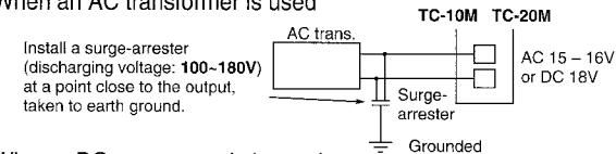
When a DC power supply is used: On the power supply with grounding terminal, be sure to take the terminal to earth ground. In this case, it is not necessary to connect a surge-arrester.
When using a power supply that has no grounding terminal, install a surge-arrester in the same manner as stated above. Surge-arrester SA-1 is available from Aiphone.
Examples of Symbols;

GENERAL PRECAUTIONS
The mark indicates caution statement (incl. danger and warning), which is specifically shown inside.

GENERAL INSTRUCTIONS
The mark indicates contents which demands a specific action shown inside or attached.
GENERAL PROHIBITIONS
The \( \sum_{\text{mark indicates contents}} \) which prohibit a specific action shown inside or attached
DISMANTLE PROHIBITIONS MOISTURE
★ All the products of other manufacturers, power supply, buzzer, etc. used for TC-M, are not within our warranty, and must be used under manufacturer or distributor's specifications and warranty

SYSTEM OUTLINE & COMPONENTS
System outline
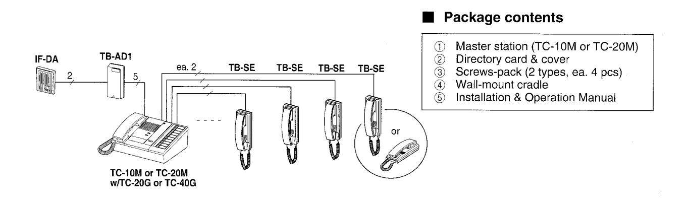
The TC-M is an internal telephone type system, expandable up to 60 subs and 2 masters. Communicates with TB-SE handset subs and IE/IF door stations.
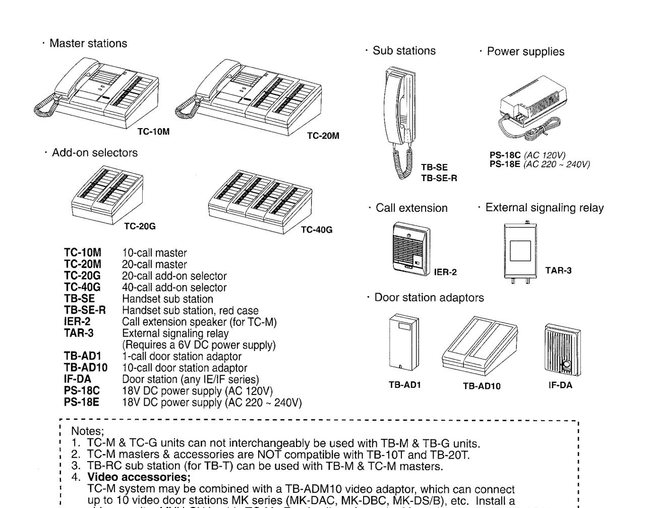
video monitor MYH-CU beside TC-M. For details, refer to the Manual packed with TB-ADM10.
2 NAMES & FEATURES
■ Names & functions
TC-10M and TC-20M master station is streamline and modernly designed. The master console may be placed on desk or wall-mounted.
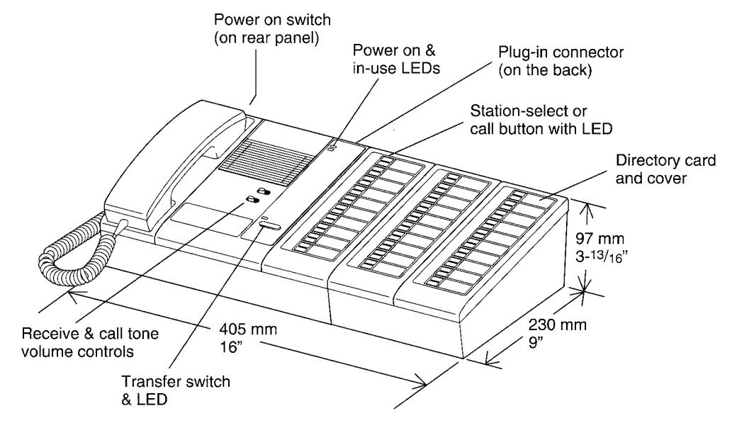
TC-10M with TC-20G add-on selector
The selector switch bank is aligned vertically, with each station having its own directory. Station numbers count top to bottom 1 to 10 on first switch bank, and 11 to 20 on the second switch bank of TC-20M. The supplied directory card and cover can be attached from the left.
Features Transfer switch and LED in the center of front panel. Single transfer button automatically connects the master with the next TB-SE sub that has called (max. 2)
TC-20G or TC-40G add-on selector plugs into TC-M back panel, and can be placed on either side of master.
Features
- TC-20G or TC-40G add-on selector connects additional TB-SE subs, allowing system expansion.
- · One or dual-master configuration.
- TB-AD1 adaptor connects TC-M with an IE/IF Series audio door station (up to 3).
- For 4 to max. 10 doors, use a TB-AD10 adaptor. Or alternatively, TB-ADM10 adaptor for max. 10 PanTilt door stations. Allows TC-M to communicate and monitor each MY door station audio-visually either selectively or all in succession. Refer to the TB-ADM10 Manual.
- Call extension IER-2 allows incoming call tone to be heard at a remote location.
- Master station can call sub by tone, and optional external buzzer.
WIRING
■ Terminal-block layout
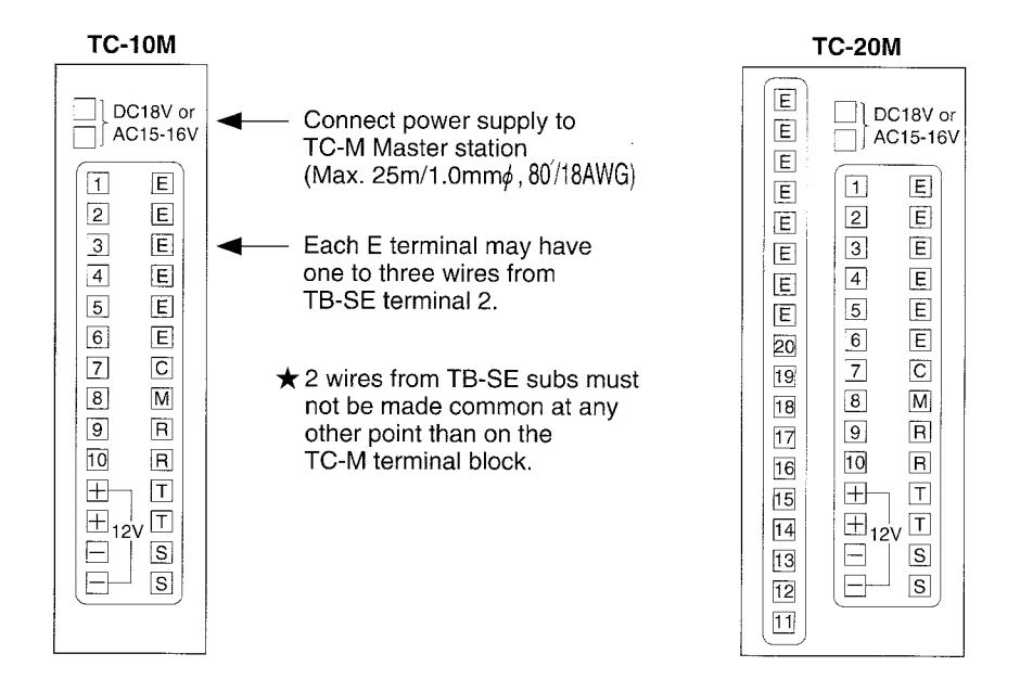
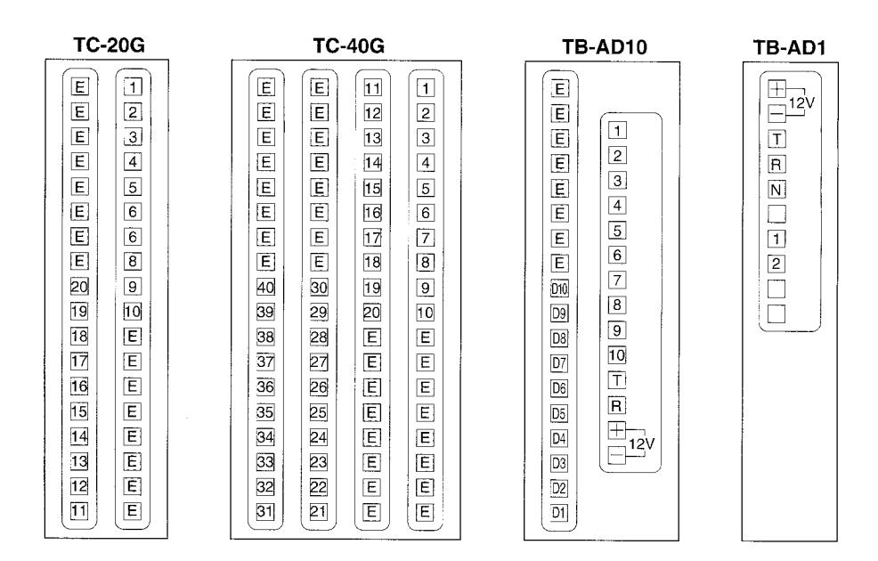
Meaning of terminal symbols
E terminal is common calling and communication line.
No. 1~40 terminals are selective station points, providing selective calling and communication.
C & M terminals are master-to-master communication.
R & T terminals are master-to-door adaptor transmit and receive lines.
S & S terminals are call tone output to IER-2 call extension speaker.
Cable requirements
Use 2-conductor cable (twisted or non-twisted) homerun to each sub station (0.65 1.0mm , 22 18AWG).
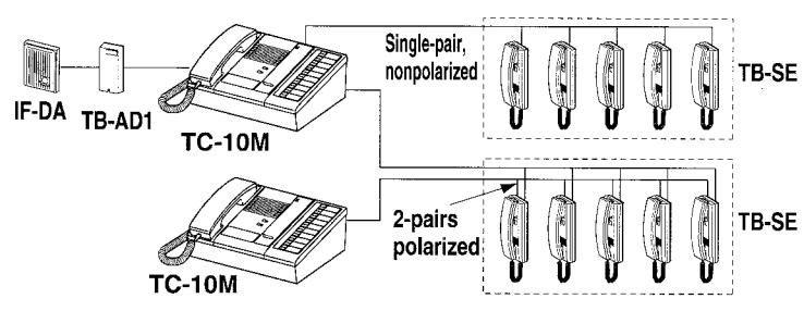
■ TC-10M single-master system with a door station
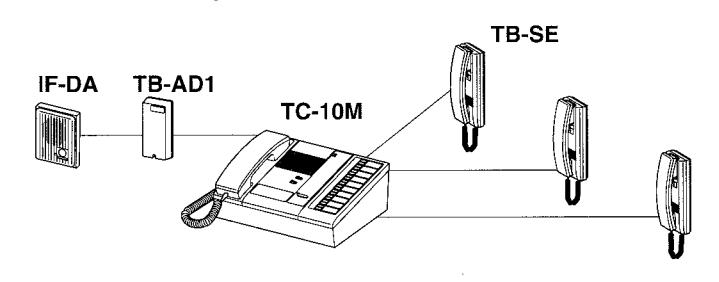
- The # terminals on the master station connect to terminal 1 on each TB-SE sub. These numbers become the sub's station number, numbered from the top on each 10-button row.
- ★ 2 parallel wires per TB-SE sub, nonpolarized. Be sure to run each pair of wires directly to TC-M master.
E line in each pair should not be connected at any other point of cable than E terminals on TC-M, which can accomodate 2 ~ 3 TB-SE subs.
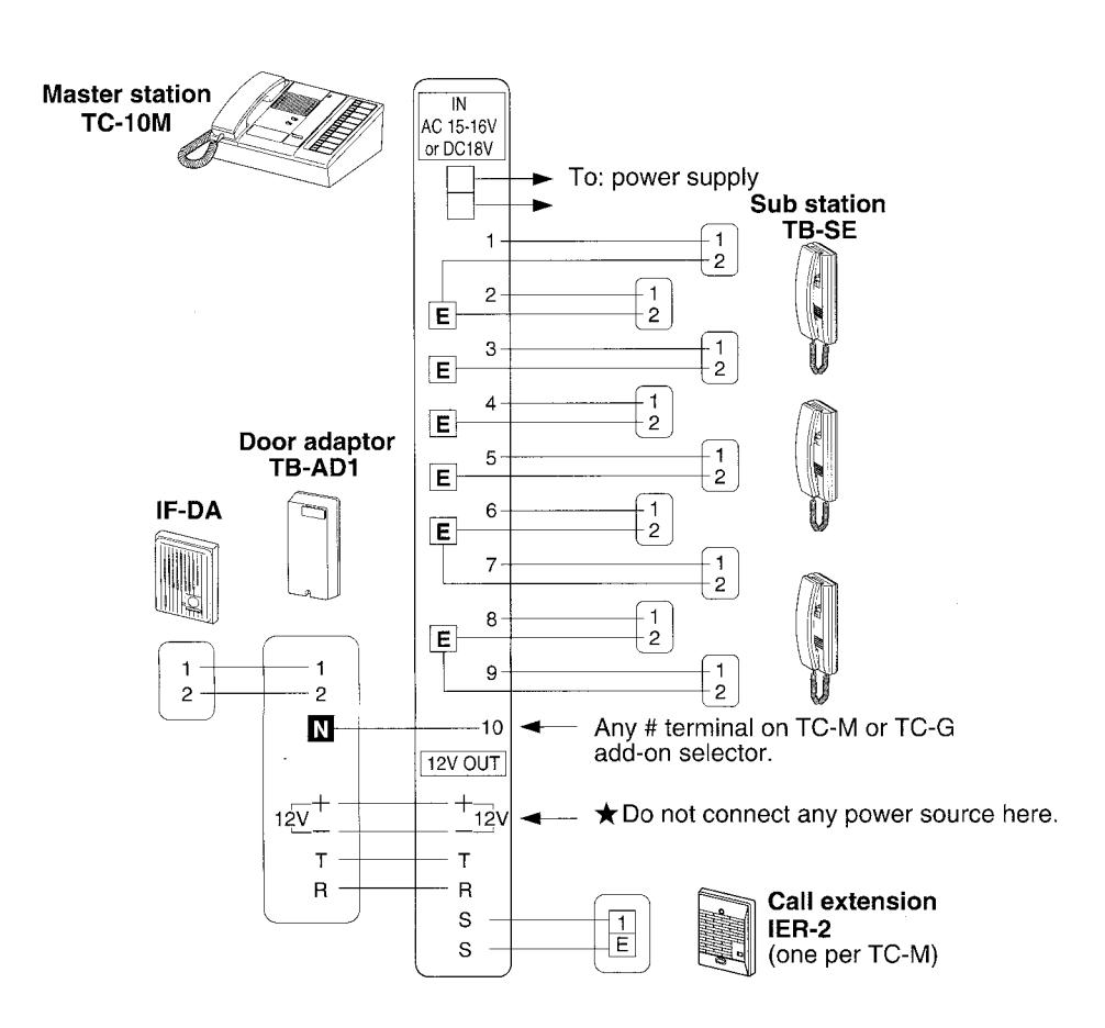
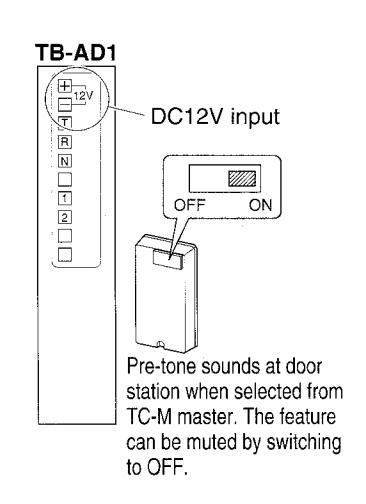
The master can select the door station for audio monitoring at any time. The call announce pretone is selectable.
Set the switch to ON position for pretone, removing the cover of front case.
■ Wiring distance
TC-M to TB-SE sub
| Diameter | 0.65mm | 0.8mm | 1.0mm |
|---|---|---|---|
| Distance | 400m | 600m | 900m |
TB-AD1 to audio door station
| Diameter | 0.65mm | 0.8mm | 1.0mm | |
|---|---|---|---|---|
| Distance | 150m | 230m | 360m | |
TC-M to TB-AD1
| Diameter | 0.65mm | 0.8mm | 1.0mm | |||
| ļ | Distance | 65m | 100m | 150m | ||
| AWG | 22AWG | 20AWG | 18AWG |
|---|---|---|---|
| Distance | 1,300' | 2,000' | 3,000' |
| AWG | 22AWG | 20AWG | 18AWG |
|---|---|---|---|
| Distance | 500' | 750' | 1,200' |
| AWG | 22AWG | 20AWG | 18AWG |
|---|---|---|---|
| Distance | 210' | 330' | 495' |
■ TC-10M single-master with TC-(20,40)G add-on selector
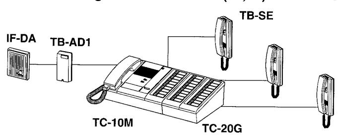
TC-M master, with a TC-G add-on selector, expands its capacity up to 60 substations. Choose the master and add-on selector to meet your system's requirements.
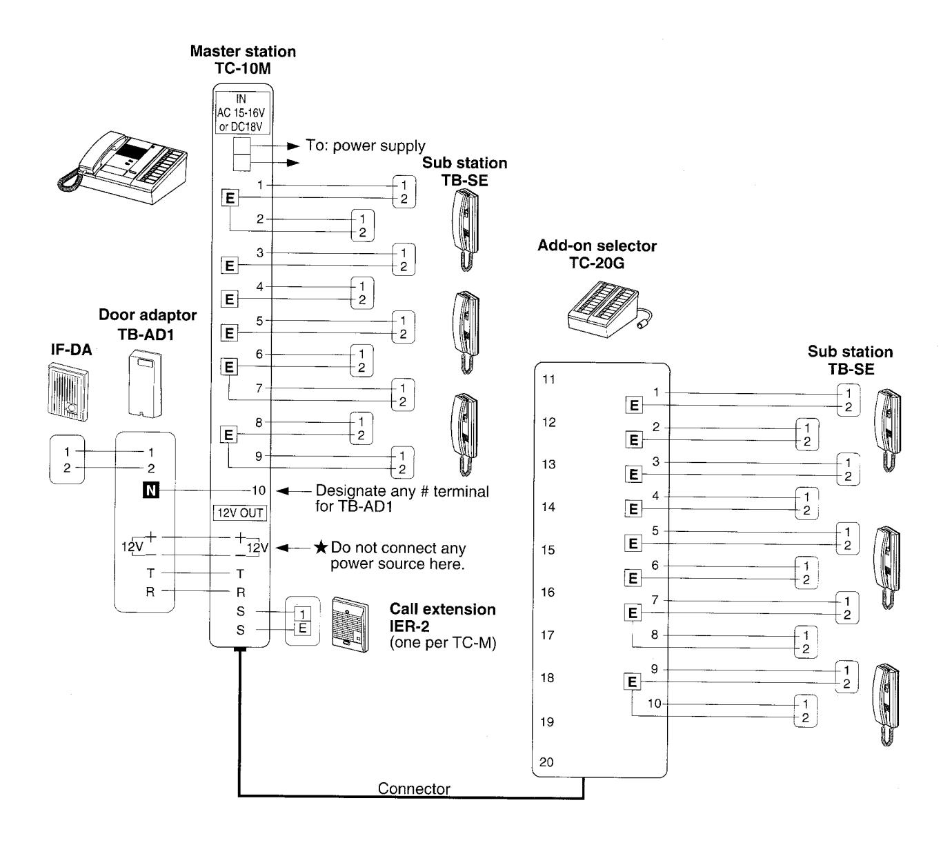
★ Up to 3 TB-AD1 door station adaptors per TC-M. 5 wires homerun to TC-M.
■ TC-20M single-master with up to 10 door stations
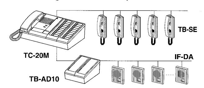
In place of TB-SE handset subs, TC-M master may have max. 10 door stations, by using a TB-AD10 adaptor.
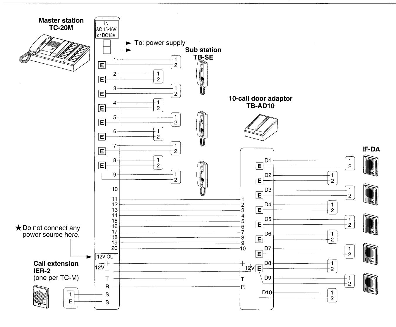
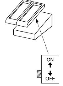
TB-AD10, 10-call door adaptor may be wired to any # terminal on TC-M or TC-G add-on selector. connecting max. 10 IE/IF door stations. Features two-way calling and communication with door station, including optional pretone. Set the switch to ON position, if pretone to door is required.
■ Wiring distance:
TC-M to TB-AD10
| Diameter | 0.65mm | 0.8mm | 1.0mm |
|---|---|---|---|
| Distance | 65m | 100m | 150m |
| ).65mm | 0.8mm | 1.0mm |
|---|---|---|
| 65m | 100m | 150m |
TB-AD10 to audio IF-DA
| Diameter | 0.65mm | 0.8mm | 1.0mm |
|---|---|---|---|
| Distance | 150m | 230m | 360m |
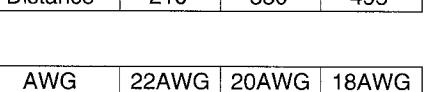
| AWG | 22AWG | 20AWG | 18AWG |
|---|---|---|---|
| Distance | 210' | 330' | 495' |
750'
1,200
TB-AD10
500'
Distance
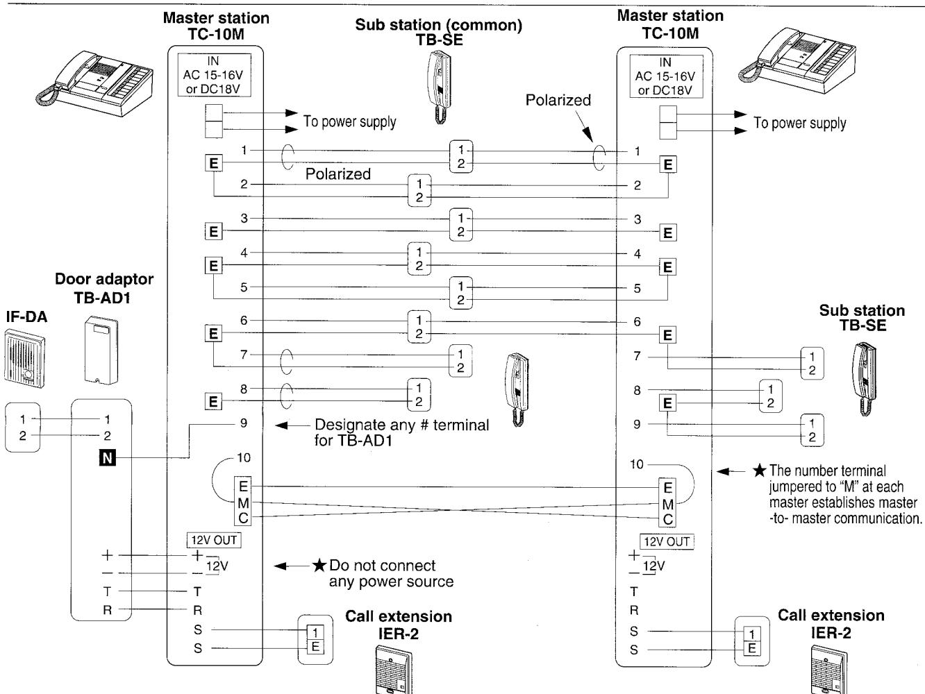
■ TC-M dual-master system
- Common TB-SE sub rings two TC-M Masters.
- Each master can call TB-SE sub selectively.
- Master-to-master communication.
★IMPORTANT
Do not use the following wiring methods. They will cause the system to malfunction:
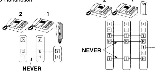
Do not parallel sub station wires between TC-M master stations. Wiring from TB-SE must be homerun to EACH master station.
Diameter 0.65mm 0.8
■ Wiring distance:
| 0.65mm | 0.8mm | 1.0mm |
|---|---|---|
| 200m | 300m | 480m |
| AWG | 22AWG | 20AWG | 18AWG |
|---|---|---|---|
| Distance | 650' | 1,000' | 1,570' |
Door adaptor TB-AD1(10) can only be wired to one master. Doors cannot call both master stations.
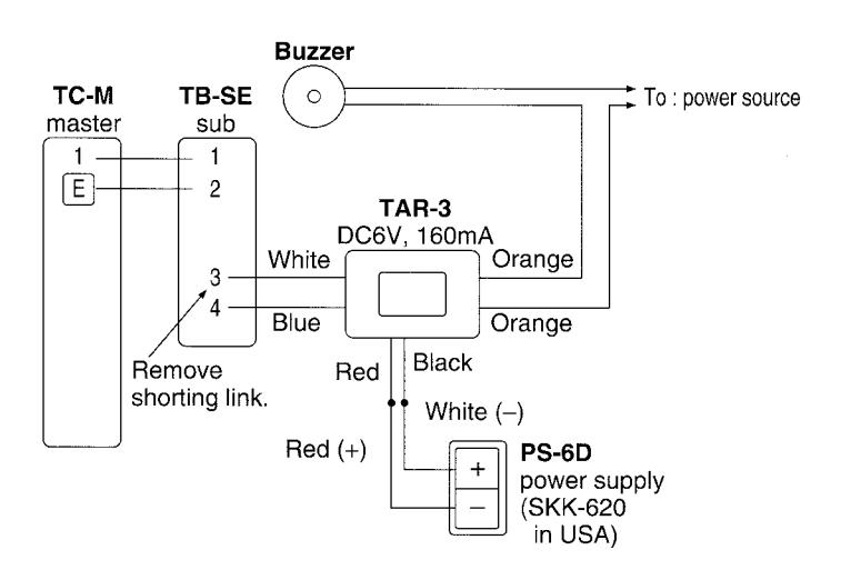
■ Connecting a buzzer at a TB-SE sub
When called by TC-M master, buzzer is activated and on TB-SE sub, call tone sounds at reduced volume.
TAR-3 relay activates an AC-operated buzzer: AC 240V, 0.3A. DC-operated buzzer must be mechanical type: DC 24V, 1.0A.
Do not use DC electronic buzzer.
MOUNTING
■ TC-(10,20)M with TC-(20,40)G
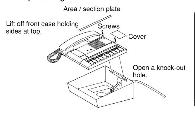
Remove 2 screws on front panel, removing the cover on upper end and area/section plate. Lift off front case holding sides at top. Disconnect the intercom by unplugging the connector. Open a cable inlet hole (rubber part) on bottom of chassis. Pull in cable(s), and make wire terminations.
Open a cable inlet hole (rubber part) on bottom of chassis. Pull in cable(s), and make wire terminations Use attached cable clamps(s) for neat and secured connection. Reconnect and mount front case to chassis, attaching the cover and plate in place.
When wall-mounting, separate the front panel from chassis, as explained above. Install the chassis upside down on the wall, onto a single-gang or two-gang box.
Desk-top mounting
Wall-mounting
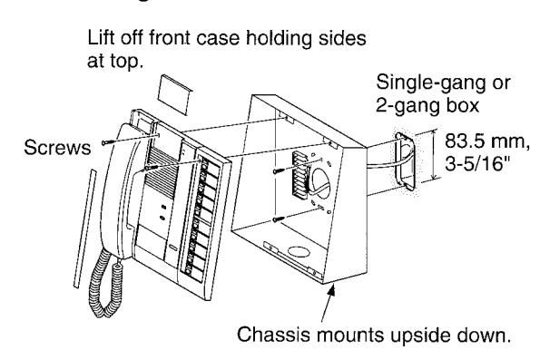
★ TC-M master wall-mounts with TC-G (and TB-AD10) attached.
Decide the exact location of TB-M master, and use the following measurements to mount the add-on components.
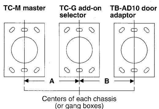
Wall-mounting guide
| Master | Attached | Guide A | Attached | Guide B |
|---|---|---|---|---|
| TC-20G | 202.5, 8" | TB-AD10 | 150.0, 6" | |
| TC-10M | TC-40G | 277.5, 11" | TB-AD10 | 225.0, 9" |
| TB-AD10 | 202.5, 8" | |||
| TC-20G | 240.0, 9-1/2" | TB-AD10 | 150.0, 6" | |
| TC-20M | TC-40G | 315.0, 12-1/2" | TB-AD10 | 225.0, 9" |
| TB-AD10 | 240.0, 9-1/2" |
OPERATIONS
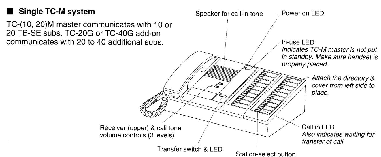
■ TC-M single-master system
Calling and receiving
Station-select outton for sub, door or master Red LED
Do not press more than one buttons, when calling.
To call a TB-SE sub, the other master or audio door station pick up handset and depress a station-select button. When called by tremolo tone, pick up and depress the LED-lit select button. LED remains on while in communication. Communicating TC-M is notified of a call with a lit LED only. The audible call tone will resume when the handset is hung up.
Receiving a call from audio IE/IF door station
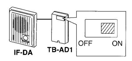
When the door station places a call with call button, a tremolo tone is activated on the TC-M, which stays on approx. 40 seconds. The master replies by selecting the station button that is lit. At the door station, when selected, a pretone is heard, unless it is muted at the TB-AD1, 10 adaptor.
"Transfer" allows two TB-SE subs to communicate with each other
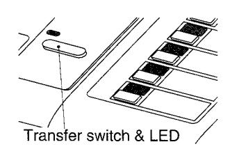
When a master receives a call from sub A, requesting transfer of call, TC-M leaves sub A waiting, pressing a sub B select button. When sub B picks up the call (sub A hears a busy tone), TC-M depresses Transfer switch.
TC-M then reselects waiting sub A with red LED on. Three parties are on the line, and TC-M may hang up.
- ★ Door-to-master or master-to-master calls are not transferrable.
- ★ If transfer LED is lit when a transfer is not being made, it can be cleared by pressing "transfer" switch.
TC-M places a buzzer-activating call to a TB-SE sub
Buzzer sounds continuously at TB-SE sub, in addition to ordinary tremolo. Pick up on the TB-SE station, that the buzzer is connected to.
Adjusting receive and call tone volume
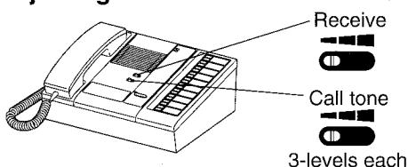
Upper control adjusts handset receiver volume, when TC-M does not hear a TB-SE sub clearly. Tone control adjusts ringing tremolo. 3 levels.
■ TC-M dual-master system
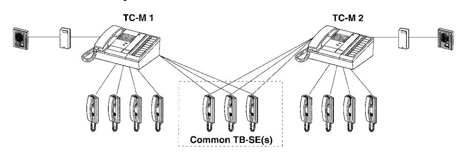
Two masters call and communicate with each assigned select button. Transfer of a sub's call to another on the other master is not possible.
A call from TB-SE subs that are connected to two masters activates tremolo tone at both masters. When the controlling TC-M is busy, the other TC-M may pick up. In this case, the sub hears both tremolo and busy tones.
★ Dual-master has an operation that, when TC-M1 places a call to either TC-M2 or a common TB-SE that is already in communication, the talk line is connected among 3 parties. It reduces communication volume. One party should hang up to restore normal volume.
■ TB-SE sub operation
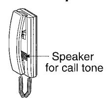
To call TC-M master, simply pick up and it rings TC-M with tremolo tone, which continues ringing until the call is answered. Intermittent tone means the master is occupied. Hang up or continue to hold. When called by tremolo tone, simply pick up.
TECHNICAL PRECAUTIONS
- ★ The power switch is located on back panel of TC-M console, which should be placed ON, except for special occasions. If the system malfunctions, turn off and on TC-M master, by which the system may reset itself. Possible causes are; power supply is unplugged, connecting wires are loosened or shorted. Do not attempt to open TC-M equipment nor change wiring. Ask gualified personnel.
- ★ At end of each communication, be sure to place handset in cradle properly. If not, TC-M master or TB-SE sub will not hear the call tone.
- ★ The TC-M is rated to operate at temperatures between 0°C ~ +40°C (32°F ~ 104°F).
- ★ Clean the TC-M equipment with a soft cloth dampened with neutral household cleanser. Never use any abrasive cleaner or cloth.

SPECIFICATIONS
Power source Power consumption
DC18V, 350mA max. or AC 15 - 16V, 50/60Hz. 750mA max.
6W max. 3W (standby)
Capacity 60 stations max.. TB-SE or door stations incl.
One add-on selector TC-20G or TC-40G per TC-M. 1 to 3 TB-AD1 door adaptors or one
TB-AD10 only alternatively, or one TB-ADM10 only
Calling TB-SE sub's call-in is annunciated with intermittent tremolo tone and LED lighting in red.
both of which are held (approx. 40 seconds for IE/IE door stations).
Station-select button calls each TB-SE with intermittent tone. Corresponding LED is lit to indicate which sub is called. Master can call IE/IF door station by voice, with or without pretone (selectable).
Communication
Both stations communicate simultaneously via handset.
Wiring
2 conductors (parallel) or a pair in multi-cond, cable TC-M to ea. TB-SE
5 conductors TC-M to TB-AD1
14 conductors max TC-M to TB-AD10
3 conductors between TC-M's
★ In TC-M dual-master system, two parallel conductors cables are required for each common TB-SE sub
Wiring distance
| 0.65mm ∲ | 0.8mm ∲ | 1.0mm ∲ | 22AWG | 20AWG | 18AWG | |
|---|---|---|---|---|---|---|
| TC-M to TB-SE | 400m | 600m | 900m | 1,300' | 2,000' | 3,000' |
| TC-M to TC-M | 200m | 300m | 480m | 650' | 1,000' | 1,570' |
| TC-M to TB-AD1 | - 65m | 100m | 150m | 210' | 330' | 495' |
| TC-M to TB-AD10 | 03111 | 100111 | 150111 | 210 | 330 | 495 |
| TB-AD1(10) to IE/IF door | 150m | 230m | 360m | 500' | 750' | 1,200' |
Compatibility
TC-M system components: TC-(10,20)M, TC-(20,40)G & TB-AD(1,10), cannot be intermixed with TB-(10,20)T masters, while TB-RC handset sub can be used with TC-M system.
Dimensions & weight
| Model | Height Width Depth | Height Width Depth | Weight |
|---|---|---|---|
| TC-10M | 117 mm x 255 mm x 230 mm | 4-5/8" x 10" x 9" | 1.8 kg (3.97 lbs.) |
| TC-20M | 117 mm x 330 mm x 230 mm | 4-5/8" x 13" x 9" | 2.3 kg (5.07 lbs.) |
| TC-20G | 97 mm x 150 mm x 230 mm | 3-13/16" x 6" x 9" | 1.0 kg (2.20 lbs.) |
| TC-40G | 97 mm x 300 mm x 230 mm | 3-13/16" x 11-13/16" x 9" | 1.9 kg (4.19 lbs.) |
| TB-AD10 | 97 mm x 150 mm x 230 mm | 3-13/16" x 6" x 9" | 1.1 kg (2.43 lbs.) |
| TB-AD1 | 140 mm x 74 mm x 42 mm | 5-1/2" x 3" x 1-5/8" | 160 g (0.35 lbs.) |
######################################
Aiphone warrants its products to be free from defects of material and workmanship under normal use and service for a period of one year after delivery to the ultimate user and will repair free of charge or replace at no charge, should it become defective upon which examination shall disclose to be defective and under warranty. Aiphone reserves unto itself the sole right to make the final decision whether there is a defect in materials and/or workmanship; and whether or not the product is within the warranty.
This warranty shall not apply to any Aiphone product which has been subject to misuse, neglect, accident, or to use in violation of instructions furnished, nor extended to units which have been repaired or altered outside of the factory. This warranty does not cover batteries or damage caused by batteries used in connection with the product.
This warranty covers bench repairs only, and any repairs must be made at the shop or place designated in writing by Aiphone.
‡ Aiphone will not be responsible for any costs incurred involving on site service calls. * **********************************
AIPHONE CO., LTD., NAGOYA, JAPAN AIPHONE CORPORATION, BELLEVUE, WA, USA AIPHONE EUROPE N.V., ANTWERP, BELGIUM
Providing Peace of Mind Printed in Japan (E)