Aiphone PD-2 Talback Paging Adaptor Installation Instructions
Open the original PDF document
View PDF

TALKBACK PAGING ADAPTOR
MODEL: PD-
Talkback paging adaptor, 1 zone for TD-H & TD-Z systems
INSTRUCTIONS

NAMES AND FUNCTIONS
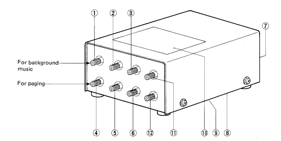
- Volume control
- (2 ) Bass control
- Treble control
- Volume control
- Bass control
- (6) Treble control
- for paging
- (7) Terminal block
- (8) Pre-tone volume control (bottom)
- (9) Connection diagram label
- (10) Control identification label
- (1) Talkback volume control
- Talkback noise control (to tune out or reduce line noise on talkback)

FEATURES
- *Provides a zone page with talkback for Aiphone's TD-H and TD-Z systems.
- *Multiple paging zones with talkback may be established. A station capacity must be deducted for each talkback paging zone.
- *One PD-2 adaptor suffices for talkback paging. PD-1 is not required.
for background music
- *Individual volume and tone controls for background music and paging.
- *Pre-tone prior to paging announcement to draw people's attention.

* Installation;
- 1. Do not attempt to install your PD-2 adaptor until you have read and thoroughly understand the installation procedure. Requirements indicated under SPECIFICATIONS on Page 6 of this Manual must be met. Aiphone's warranty for the adaptor and the system is void if adaptor is installed in a manner other than described in this manual.
- 2. DO NOT CONNECT ANY TERMINAL ON ANY UNIT TO AC POWER LINES.
- 3. Select the installation locations that would not be exposed to temperature/humidity extremes, water, oil, dust, iron dust, inflammable & chemical products, etc.
- 4. Be sure not to plug power supply into AC receptacle until you complete wiring connections, and unplug before opening the unit.
| _ | |
|---|---|
| 5. General notes on paging equipment installation; | |
| ① Wiring from M, G and A terminals (PD-2) to BGM source and paging amplifier input; Use shielded wires and locate PD-2 adaptor(s) as close as possible to the amplifier and BGM source. | |
|
|
| ③ It is recommended that AUX terminals be used for amplifier input. If PHONO input is used, the sound quality of both paging and BGM would deteriorate due to the RIAA equalizing circuit that is normally used in PHONO input circuitry. In case PHONO input must be used, make tone adjustment on PD-2 adaptors, taking the above into account. | 5 |
| (4) It is suggested that PD-2 adaptors should be installed near the center of the system, along with power supply PS-12A (o PS-12C). However, PD-2 must be kept more than 20 cm (8") away from PS-12A (or PS-12C) to avoid inductive noise. | |
| Unit selection; |
- 1. Installation of a paging zone deducts a station capacity in TD-H or TD-Z systems.
- 2 If talkback is required, select a PD-2 adaptor. PD-1 adaptor is not required.
* Operation;
- 1. On TD-H station, do not depress more than one number buttons each assigned for paging zone.
- 2. Do not depress number buttons for (talkback) paging zone and communication simultaneously. It may cause an incomplete paging announcement to be and high-pitched noise to come out from the speakers.

(1) ACTUAL TERMINAL LOCATION;
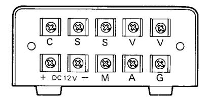
[C] : for paging input and zone selection. [S] , [S] : for connecting to the paging speakers. [V] , [V] : for connecting to the amplifier output.
+ , - : for connecting to power supply PS-12A (or PS-12C).
M, G: for connecting to music output. A , G: for connecting to the amplifier input.
(2) WALL-MOUNTING INSTALLATION;
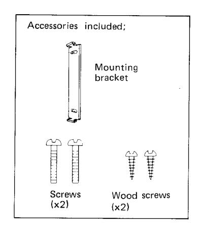
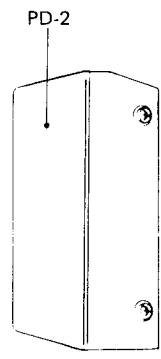
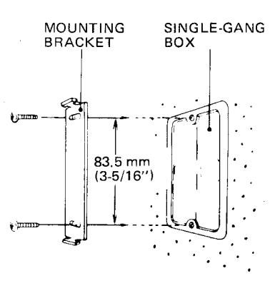
PD-2 is shipped with the mounting bracket. Attach the mounting bracket to single-gang box or to wall/rack, with the supplied screws. Insert the prongs of the bracket into the holes on back of the adaptor and pull the body downward.
(3) PAGING SPEAKERS INPEDANCE-MATCHING;
*Determine the number of the speakers and output power for each so that the total of required power for the speakers will be equal or less than the rated output power of the amplifier.
* Impedance matching table (Example);
| Model | Rated input | Impedance | speaker input | T 1 | |
|---|---|---|---|---|---|
| 100 V line | 70 V line | Terminals | |||
| SP – 3NA | 3 W | 10 K ohm | 1 W | 0.5 W | 0 – 3 |
| 5 K ohm | 2 W | 1 W | 0 - 2 | ||
| 3.3 K ohm | 3 W | 1.5 W | 0 – 1 | ||
(4) ADJUSTING CONTROLS;
Upon completing all the wiring connections, proceed with the following steps before turning the system on.
- 1. Set PD-2 adaptor VOLUME, TREBLE & BASS controls (and of paging amplifier and BGM source, if included) at MIDPOINT.
- 2. Set also TALKBACK VOLUME & NOISE controls at MIDPOINT.
- 3. Turn on power supply PS-12A (or PS-12C) of TD-H or TD-Z system, paging amplifier & BGM source.
- 4. Initiate paging or talkback operations (prior to BGM control adjustment).
- 5. Adjust paging VOLUME control on PD-2 to achieve desired level. Fine tune paging TREBLE & BASS controls on PD-2. In places where a TD-H/TD-Z station is located near the paging speakers, feedback might take place if the paging volume is too high.
- By PD-2 noise control, tune out or reduce interference on talkback only created by line induction and then adjust talkback volume.
NOTE: When adjusting talkback level we recommend having a radio playing or an assistant available in the talkback paging zone to facilitate proper volume adjustments.
Adjust PD-2 background music VOLUME control to achieve desired background music level. Fine tune background music TREBLE & BASS, while listening to the background music. Adjust background music VOL-UME, TREBLE & BASS controls on BGM source, if included.

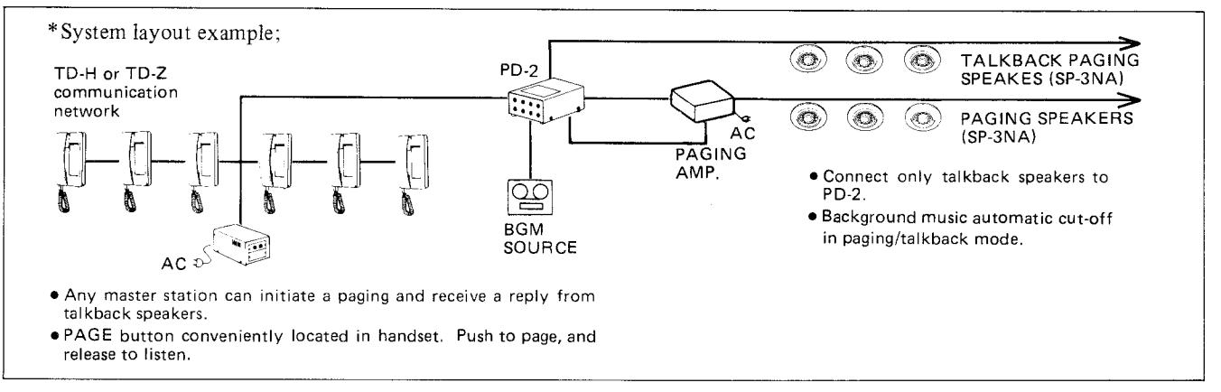
LAYOUT EXAMPLE AND WIRING DIAGRAM (1) TD-H/TD-Z SYSTEM WITH ONE PAGING ZONE WITH TALKBACK
- ① On any phone station, own No. button operates a paging with talkback.
- ② Talkback paging zone requires a PD-2 adaptor, PG-A/ PG-B paging amp. & a required number of paging speakers.
- 3) PD-2 adaptor must be powered by a system's power supply PS-12A (or PS-12C).
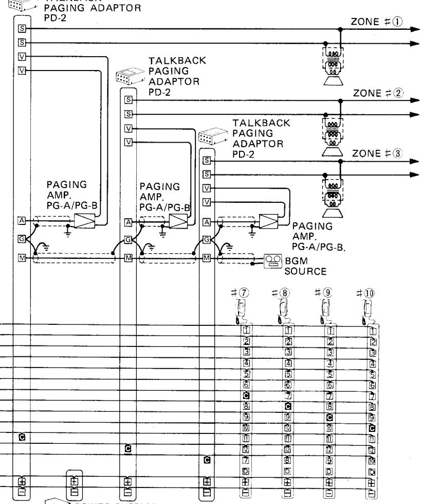
(2) TD-H/TD-Z SYSTEM WITH 3 PAGING ZONES WITH TALKBACK
TALKBACK
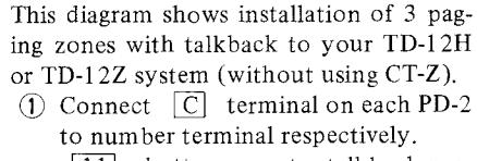
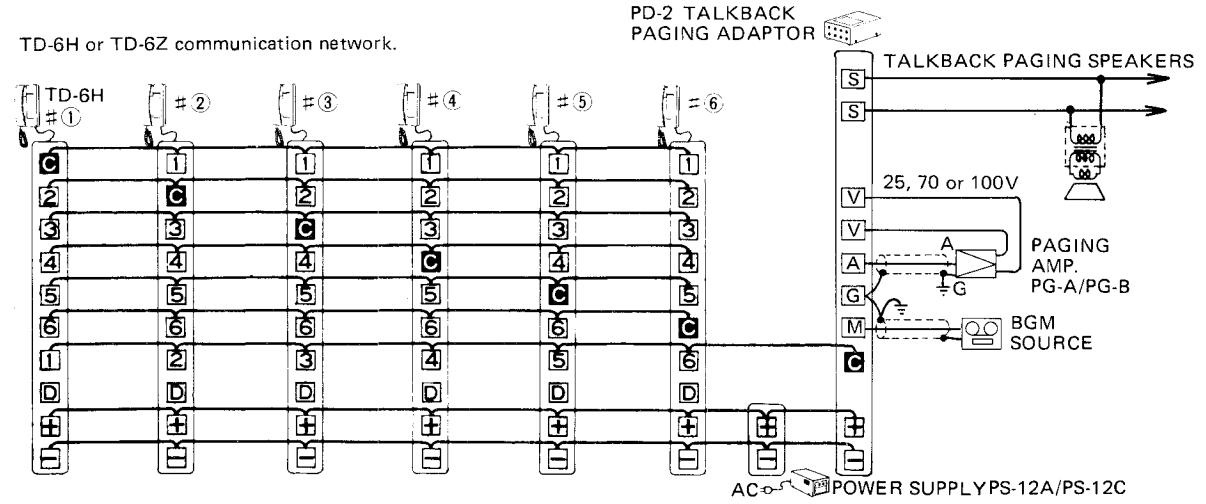
button operates talkback paging thru speakers of zone #①, 12 button thru speakers of zone #②, own No. button thru speakers of zone #③.
- ② Each zone requires a PD-2 adaptor, PG-A/PG-B paging amplifier & a required number of speakers.
- (3) PD-2 adaptors must be powered directly by PS-12A (or PS-12C) power supply (not indirectly from communication network).
TD-12H or TD-12Z (without CT-195Z) communication network #2 #3 #4 #5
Ò
4
(5) (6)
(7)
(9)
fin
m
Ø
6
Ē
9
flo
#1
Ø
121 131
5
Œ
Ċ
[4]
8
9
Ō m m 12 12 12 12 Œ 2 4 5 6 D D П D Ħ Ð Æ POWER SUPPLY PS-12A/PS-12C
ă
2
4
Ø
6
(Ž)
g
lio
#(6)
2
4
ĕ
7 8
9
_ 4 _
(3) TD-12Z HOME-RUN WIRED SYSTEM WITH 2 PAGING ZONES (ONE WITH TALKBACK)
This diagram shows TD-12Z system with 2 paging zones PAGING SPEAKERS (one with talkback). Assign a number terminal/button for each paging zone. ZONE #1 Own No. button for Zone #(1), button for Zone # (2). TALKBACK PAGING SPEAKERS S Connect [+] [-] [C] terminals (on CT-195Z) to each 25, 70 or + - C terminals (on PD-1 or PD-2). S 100V ZONE # 2 For straight paging, install a PD-1 adaptor, and for talkback paging, install a PD-2 adaptor. 25, 70 or 100V As shown, connect to S S terminals only speakers PAGING AMP. PAGING AMP from which talkback is required (See General notes 5 PG-A/PG-B PG-A/PG-B on Page 2). CT-195Z G Μ TD-12Z #①◀ 9999999999999 2 10 10 10 10 10 10 10 10 10 10 10 10 10 SOURCE 3 0 0 0 0 0 0 0 0 0 0 0 0 0 0 0 0 0 0 4 6 6 6 6 6 6 6 6 6 6 6 5 6 6 6 6 6 6 6 6 6 6 6 6 6 6 6 6 6 6 6 6 6 6 6 6 6 6 6 7 (A) (B) (B) (B) (B) (B) (B) (B) (B) (B) (B 8 10 10 10 10 10 10 10 10 10 10 10 10 10 · 10 10 10 10 10 10 10 10 10 10 10 10 10 10 0 0 0 0 0 0 0 0 0 0 0 0 0 0 0 0 0 0 - | 0 6 6 6 6 6 6 6 6 6 6 TD-12Z #(1) ◀ С C PAGING ADAPTOR PD-1 9 9 9 9 9 9 9 9 9 TALKBACK PAGING ADAPTOR PD-2 PS-12A/PS-12C POWER SUPPLY
Installation of paging zone (with or without talkback) reduces one station capacity of TD-Z system.
PS-12A (or PS-12C) power supply can be connected to [+], [-] terminals of any row on CT-195Z central terminal board.
Background music source can be used in common for all zones.

TD-H TALKBACK PAGING OPERATION

Pick up handset, and depress a number button for desired paging zone. Push PAGE button in handset to make announcement, and release to listen to the reply.
NOTE; When a number button A1 A12 is assigned for a paging zone (on TD-24H/24HW), select a corresponding number button and then momentarily depress button.
TD-Z TALKBACK PAGING OPERATION

Pick up handset, depress a number button for desired paging zone, and momentarily push CALL button. Push PAGE button in handset to make announcement, and release to listen to the reply.
Background music is automatically cut off during paging operation, and comes back on when handset is hung up.

SPECIFICATIONS
*Power source: DC 12V. PD-2 adaptor must be connected directly to PS-12A (or PS-12C in North America)
power supply.
*Current consumption: 48 mA maximum (in talkback mode). 20 mA maximum (in paging mode).
*Output: 5 K ohm; Max. 1.5V.
*Tone controls for music: Treble: at 10 KHz., 12dB. Bass: at 100 Hz., 12dB. Tone controls for paging: Treble: at 10 KHz., 12dB. Bass: at 100 Hz., 12dB.
*Music input: 17 K ohm, 0.3 V, 1KHz. for full output. *Talkback gain: 40 dB, 1 KHz. at maximum volume.
*Environmental noise: Less than 80dB (phon).
AMPLIFIER REQUIREMENTS;
*Input: Connect to either AUX or PHONO terminal 100K-500K ohm, .
TUNER OUTPUT REQUIREMENTS;
*Use audio output: RANGE; , 10 K ohm or less.
TAPE OUTPUT REQUIREMENTS;
*Use low level output: RANGE; , 600 ohm.
Dimensions: Height: 51.5 mm (2-1/32") x Width: 90 mm (3-9/16") x Depth: 138 mm (5-7/16")
Weight: Approximately 380 g (0.84 lbs.).
WARRANTY
Aiphone warrants its products to be free from defects of material and workmanship under normal use and service for a period of one year after delivery to the ultimate user and will repair free of charge or replace at no charge, should it become defective upon which examination shall disclose to be defective and under warranty. Aiphone reserves unto itself the sole right to make the final decision whether there is a defect in materials and/or workmanship; and whether or not the product is within the warranty.
This warranty shall not apply to any Aiphone product which has been subject to misuse, neglect, accident, or to use in violation of instructions furnished, nor extended to units which have been repaired or altered outside of the factory.
This warranty does not cover batteries or damage caused by batteries used in connection with the product.
This warranty covers bench repairs only, and any repairs must be made at the shop or place designated in writing by Aiphone. Aiphone will not be responsible for any costs incurred involving on site service calls.
Aiphone Co., Ltd., Nagoya, Japan Aiphone Corporation, Bellevue, Washington