Aiphone New GT Series Multi Tenant Entry Security Quick Start Installation Guide
Open the original PDF document
View PDF

GT SERIES
Multi-Tenant Entry Security
Quick Start Installation Guide
ATTENTION:
This is an abbreviated Installation and Programming manual for the GT Series. The complete GT Series Installation Manual is supplied with the GT-BC Bus Control Unit. Additional manuals are available online, including The GT Standard & Expanded Setting Manual and GT Multi Building Installation and Setting Manuals. If installing a digital entry system, the GT Setup Tool for programming tenant names and numbers and other settings can be downloaded from www.aiphone.net.
Table of Contents
System Wiring
| Standard system wiring: audio only | 3 |
|---|---|
| Standard system wiring: audio/video | 4 |
| Expanded system wiring | 5 |
| Option connector wiring: tenant stations | 5 |
| Settings | |
| Dip switch settings: entrance and guard station ID settings | 6 |
| Dip switch settings: entrance station | 6 |
| Programming | |
| Entering tenant information | 7 |
| Addressing tenants via dip switch method | 8 |
| Entering guard station and entrance station information | 9 |
| Transfer data to other guard stations and entrance stations | 10 |
| Uploading to stations via USB | 11 |
| GT Setup Tool for Android | |
| Downloading settings | 11-12 |
| Editing settings | 12 |
| Uploading settings | 13 |
| Programming: addressing tenants via handshake method | 14-15 |
| GT-MCX Network Adaptor | |
| Multi-Building System Wiring with GT-MCX | 16 |
| Dip switch settings: GT-MCX | 17 |
| System Programming with Multiple GT-MCX: multi-building | 18 - 19 |
| Programming: addressing tenants via dip switch method | 19 |
| Programming: entering resident info | 20 |
| Programming: entering entrance station and guard station information | 21 |
| Programming: transfer information to entrance stations and guard stations | 22 |
| Programming: uploading to MCX via LAN | 23 |
| Programming: sharing handshake data | 24 |
STANDARD SYSTEM WIRING: AUDIO ONLY
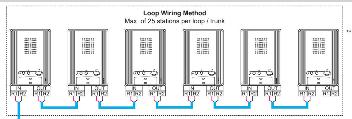
Max. wire distance from distribution point to any tenant is 980' (300m). Max. cumulative wire distance is 8200' (2500m).
Refer to the GT Series Installation Manual for complete wire distance information.
WIRE TYPE
: Audio Line 20AWG (0.8mm) 2 Cond. Solid Non Shielded PE Insulated
: Video Line 18AWG (1.0 mm) 2 Cond. Solid Non Shielded PE Insulated
POWER
PS24
PS-2420UL PS-2420
PS-2420S
PS-2420BF
РΤ
Power Transformer (Use proper power for the Strike or Mag Lock being used.)
- * Distribution Point: (GTW-DP) Available in N. America. This can be any device that parallels or commons the R1/R2 connection. (Terminal strip, punch down block, wire nuts, etc.)
- **Tenant stations shown are the GT-1A. The GT-1D tenant stations can also be used and wired in the same manner.
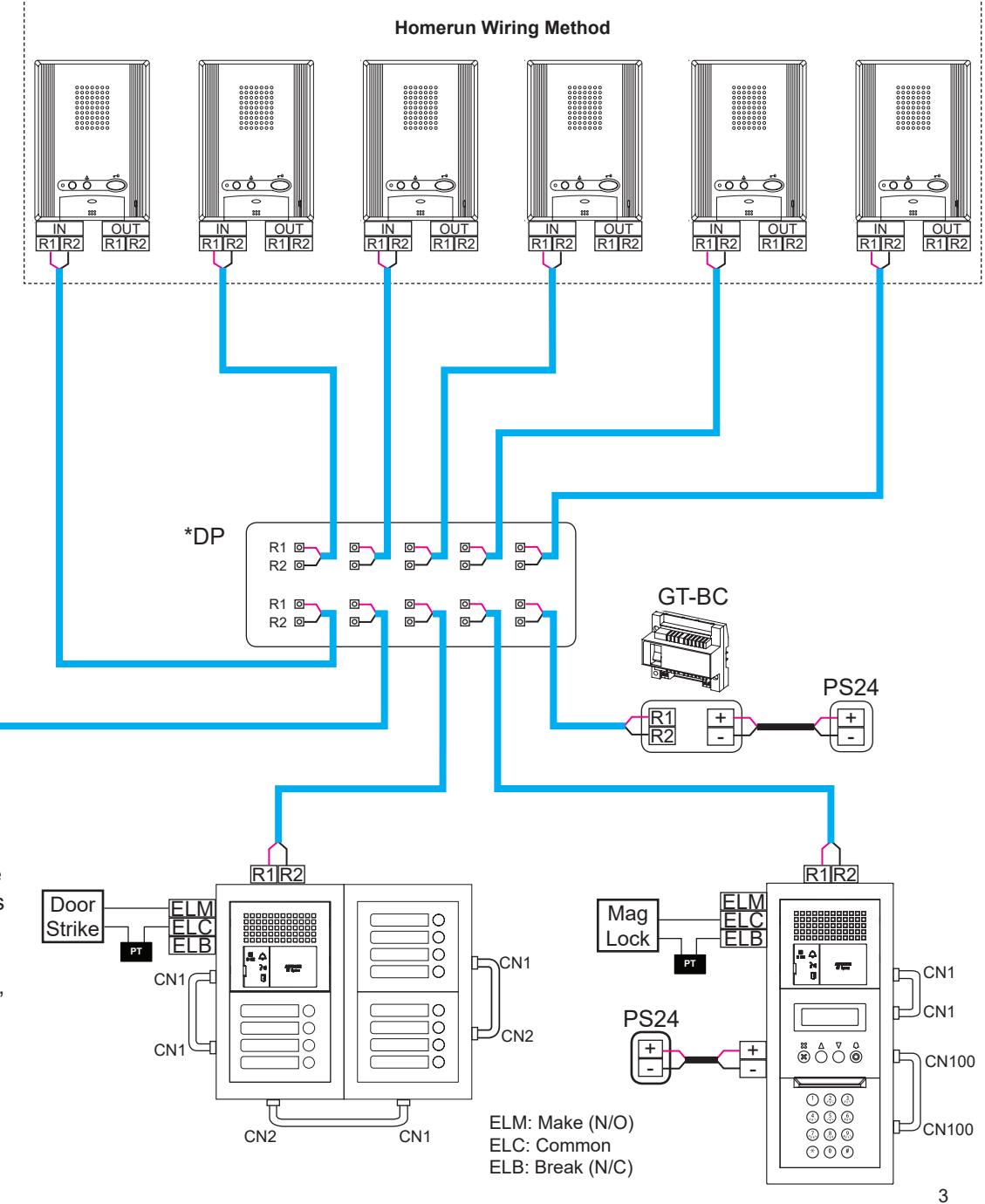
STANDARD SYSTEM WIRING: AUDIO / VIDEO
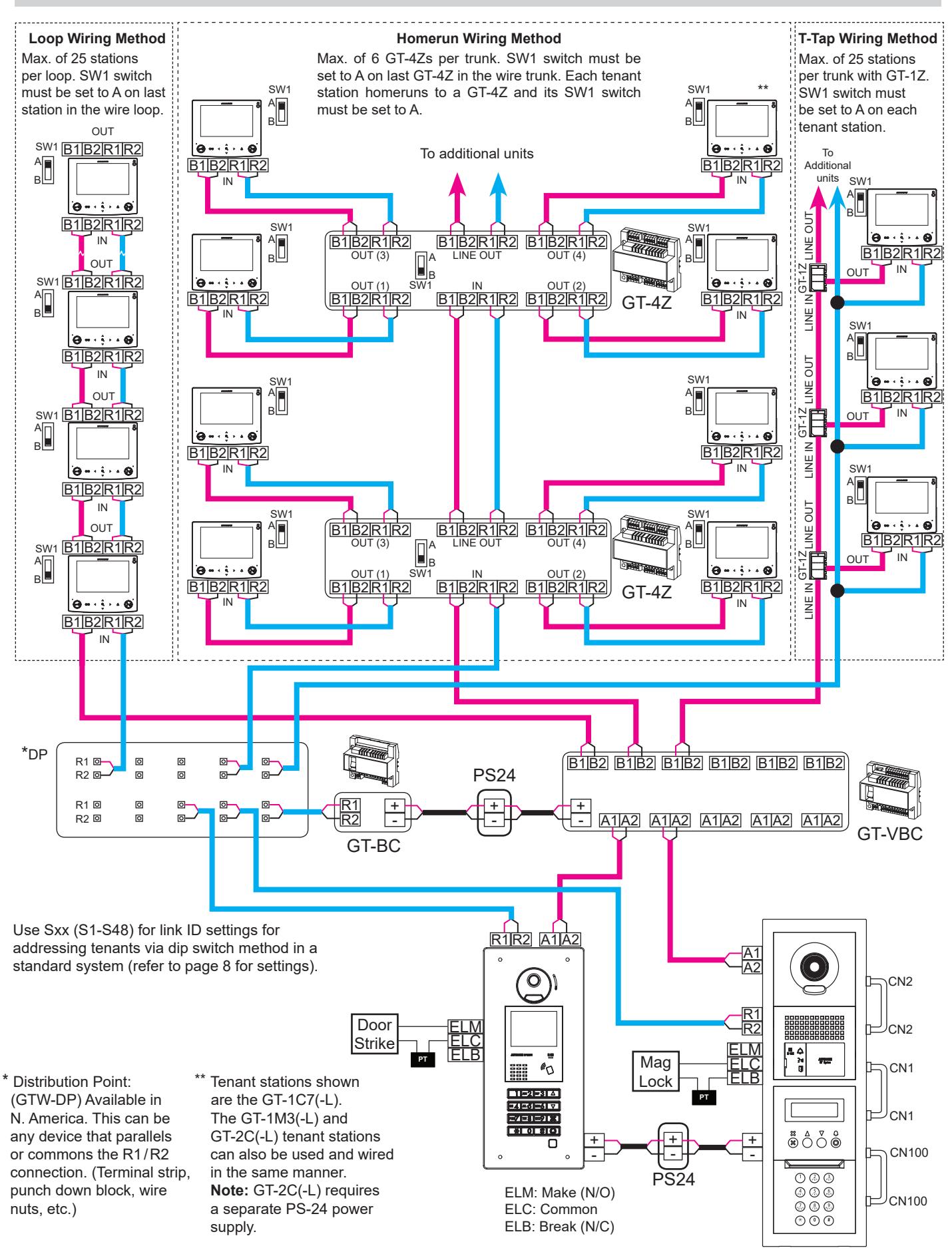
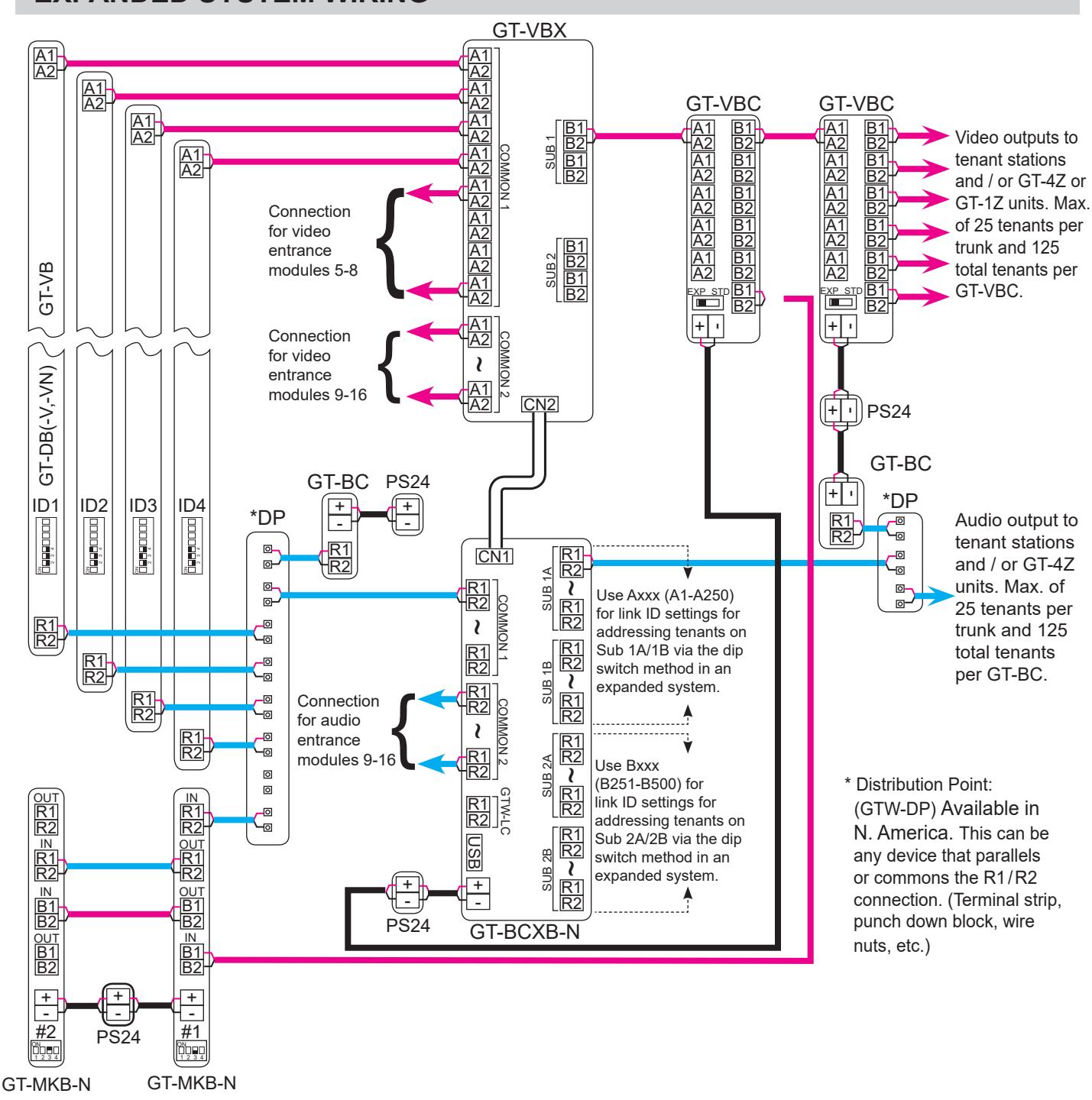
EXPANDED SYSTEM WIRING
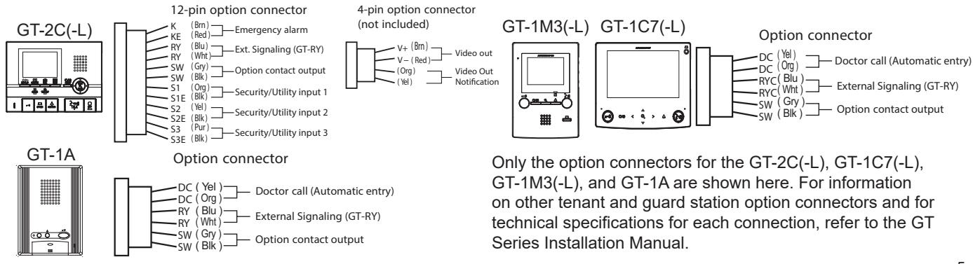
OPTION CONNECTOR WIRING: TENANT STATIONS
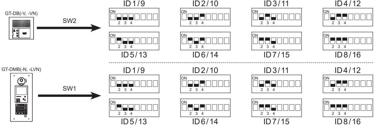
DIP SWITCH SETTINGS: ENTRANCE & GUARD STATION ID SETTINGS
NOTE:
When GT-MCX is included in the system, ID#1 cannot be used for entrance/guard stations.
Entrance ID Setting:
Use SW2 on the GT-DB(-V, -VN) module or SW1 on the GT-DMB(-N, -LVN) entrance station to set the ID for each entry panel. Switches 2 - 4 are used for this setting.
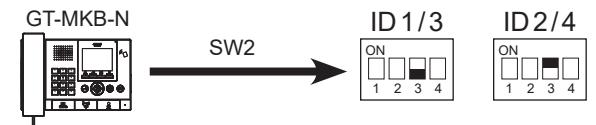
Guard ID Setting:
Use SW2 on the GT-MKB-N guard station to set the ID setting for each guard. Switch 3 is used for this setting.
DIP SWITCH SETTINGS: ENTRANCE STATION
NOTE:
When using the GT-DMB(-N, -LVN), the settings listed below will be done via the keypad / display while in programming mode. Refer to the GT Series Installation Manual for instructions.
Make sure power is removed from the system before making any dip switch changes.
Guidance Language Setting:
The audio guidance is set to off (No Guidance) by default. Use SW3 on the GT-DB(-V, -VN) module to set the appropriate language. Only switches 2, 3, & 4 are used for this setting.

Entrance Monitoring:
Use switch 5 of SW2 on the GT-DB(-V, -VN) module to enable / disable entrance monitoring. Default is "Monitoring not allowed." Enabling will allow video tenant stations to 'call up' the entrance station and monitor the door area.

Camera View:
Use switches 3 & 4 of SW1 on the GT-VB module to set the camera view. The default setting is Zoom.
Zoom 3s>>Wide: Image starts zoomed and after 3 seconds goes wide.
Wide 3s>>Zoom: Image starts wide and after 3 seconds zooms.

PROGRAMMING: ENTERING TENANT INFORMATION
The GT-DMB(-N, -LVN), GT-MKB-N, and modular digital entrance stations must be programmed with the resident's information before tenant stations can be addressed. The resident's information can be entered using the keypad or by using the GT Setup Tool software.
Programming entrance stations using the GT Setup Tool for Windows
- Step 1: Open the GT Setup Tool and click the Create new site radio button. If already in the program, under File, select Create new site(N).
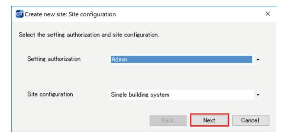
- Step 2: Leave the standard options as shown, then click Next .
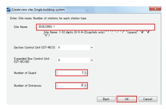
Step 3: Enter a Site Name and indicate if GT-MCX or GT-BCXB will be used. From the drop down menu, select the Number of Guard and the Number of Entrances , then click OK .
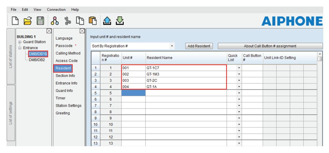
Step 4: Click the + Entrance to show all entrance stations, then select the entrance station (DMB/DB1) to program. Click Resident . Enter a Unit # (required) and Resident Name (not required, but must type in all Caps).
Step 5: Click Save , and then Yes .
PROGRAMMING: ADDRESSING TENANTS VIA DIP SWITCH METHOD
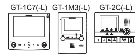
Use the dip switch method of programming shown below when installing the GT-1C7(-L), GT-1M3(-L), or GT-2C(-L). When installing the GT-1A or GT-1D, use the handshake method shown on pages 14-15 after uploading tenant, entrance, and guard information to the stations. If using a mix of stations that allow for dip switch settings (GT-1C7(-L), GT-1M3(-L), and GT-2C(-L)) and stations that do not (GT-1A, GT-1D), it is recommended to program all stations using the handshake method.
Step 1: Create an ID correlation table for the tenant stations using a binary / SW2 Dip Switch - ID chart. The chart below is for up to 48 stations in a non-expanded system. The full Dip Switch chart can be downloaded from http://www.aiphone.net/product/support/gt/
| Dip Switch | ID |
|---|---|
| S1 | |
| S2 | |
| S3 | |
| S4 | |
| S5 | |
| S6 | |
| S7 | |
| S8 | |
| S9 | |
| S10 | |
| S11 | |
| S12 |
| ID |
|---|
| S13 |
| S14 |
| S15 |
| S16 |
| S17 |
| S18 |
| S19 |
| S20 |
| S21 |
| S22 |
| S23 |
| S24 |
| ID |
|---|
| S25 |
| S26 |
| S27 |
| S28 |
| S29 |
| S30 |
| S31 |
| S32 |
| S33 |
| S34 |
| S35 |
| S36 |
| Dip Switch | ID |
|---|---|
| S37 | |
| S38 | |
| S39 | |
| S40 | |
| S41 | |
| S42 | |
| S43 | |
| S44 | |
| S45 | |
| S46 | |
| S47 | |
| S48 |
Step 2: Set the SW2 dip switches found on the back of the GT-1C7(-L), GT-1M3(-L), and GT-2C(-L) according to the correlation table created in the previous step.
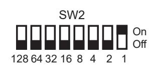
Step 3: Enter the ID from the correlation table in Step 1 into the Unit Link-ID Setting for each station.
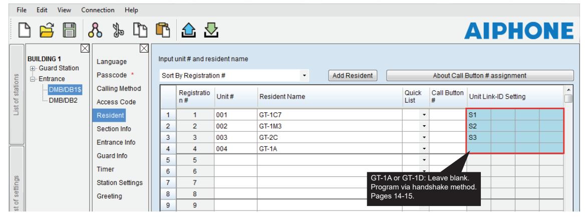
Step 4: Click Save , and then Yes .
PROGRAMMING: ENTERING GUARD STATION AND ENTRANCE STATION INFORMATION
Programming Guard/Entrance Information
Step 1: Click the + Guard Station , then select the guard station to program. Click Entrance Info , then enter 1 for the Section ID. Enter the Entrance ID (1-16), Entrance #, and Entrance Name (not required).
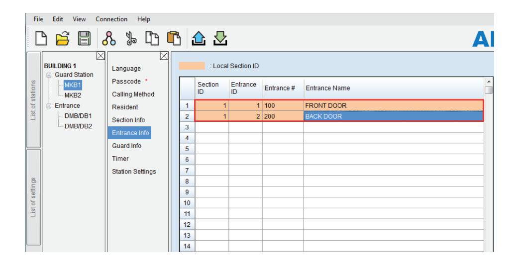
Step 2: Click Guard Info , then enter 1 for the Section ID . Enter the Guard ID (1-4), Guard # and Guard Name (not required) of the other guard station in the system.
Note: This step is not required if only using 1 guard station.
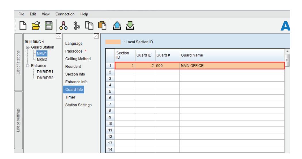
- Step 3: Repeat Steps 1 and 2 for each guard station.
- Step 4: Click the +Entrance ,then select an entrance station. Repeat Step 2 to enter the Guard Info for each entrance station. Since entrance stations cannot call other entrance stations, only guard station information will be entered for the entrance station.
- Step 5: Click Save , and then Yes .
PROGRAMMING: TRANSFER DATA TO OTHER GUARD/ENTRANCE STATIONS
NOTE:
When installing the GT-1A , GT-1D , or when not using dip switch setting method we recommend the following.
- Upload resident information to entrance/guard station (page 11 Step 1-2)
- Use handshake method to establish Link ID (page 14-15)
- Download settings from entrance/guard station
- Compare and Merge with remaining entrance/guard stations (below)
Compare and Merge (copy data to other devices in the system)
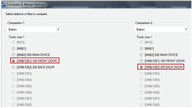
- Step 1: Click Compare and Merge Settings to copy data to other entrance and guard stations.
- Step 2: In the Comparison-1 column, select the entrance station/guard station radio button where resident information was programmed. In the Comparison-2 column, select the desired entrance station/guard station that data is to be copied to. Click Compare .

Click Select comparison and repeat until the Resident information has been copied to all desired entrance stations and guard stations.
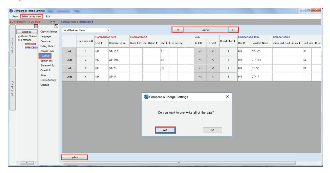
Step 4: When done, click Exit .
PROGRAMMING: UPLOADING TO STATIONS VIA USB
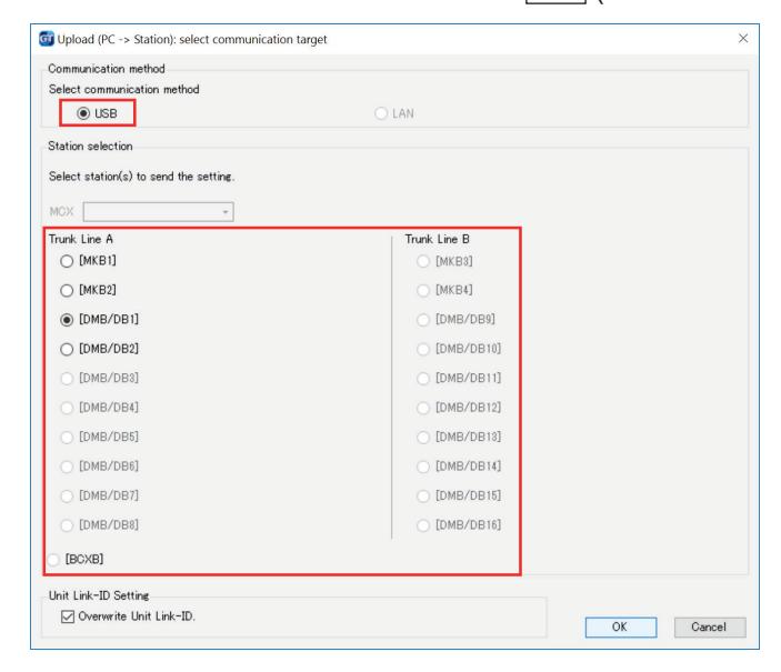
- Step 1: Click Upload .
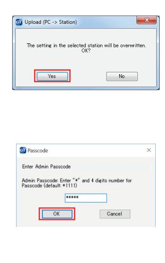
- Step 2: From the Upload (PC -> Station) menu, select the USB radio button. Select the desired station's radio button and click OK . Click Yes in the popup window asking if it's ok to overwrite the selected station. Enter the Admin Passcode then click OK (default Admin Passcode is *1111).
Step 3: Repeat for all entance/guard stations.
GT SETUP TOOL FOR ANDROIDTM: DOWNLOAD FROM GOOGLE PLAYTM
The Aiphone GT Setup Tool for Android app can be used to create and upload setting files to the GT-DMB(-N, -LVN) and GT-DB-VN entrance stations as well as the GT-MKB-N guard station. It is recommended to use the GT Support Tool for Windows for the initial setting file creation and loading to the stations, then use the app for downloading and editing the setting file when changes need to be made. The following sections will cover how the app can be used for downloading and editing the setting file, then uploading. For complete information on using the app for programming, refer to the GT SYSTEM SETTING MANUAL/Aiphone GT Setup Tool for Android.
GT SETUP TOOL FOR ANDROID: DOWNLOADING SETTINGS
Open the Aiphone GT Setup Tool for Android and tap DOWNLOAD SETTING BY NFC.
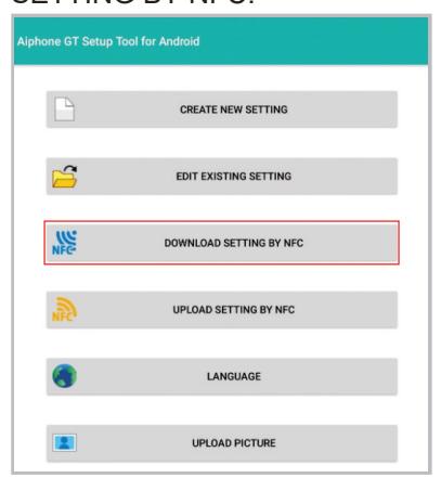
Step 1 Step 2 Step 3
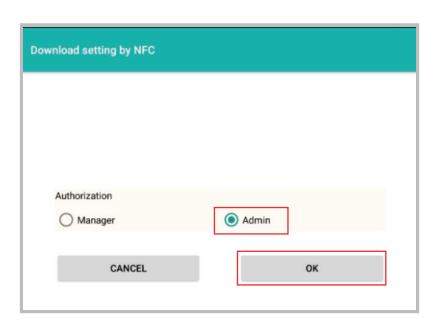
Tap the appropriate authorization level and then tap OK.
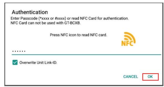
Enter the appropriate passcode (default: Admin *1111, Manager #2222). Ensure that Overwrite Unit Link-ID settings is checked, then tap OK.
GT SETUP TOOL FOR ANDROID: DOWNLOADING SETTINGS (continued)
Step 4 Step 5
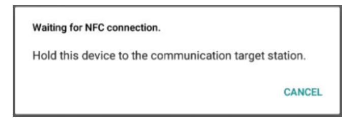
Hold the Android device to the target station to download the settings.
Step 6
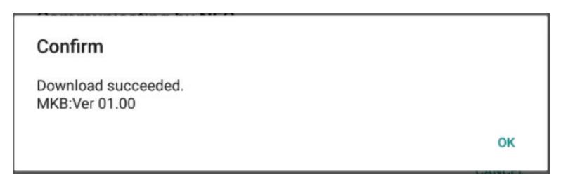
A confirmation message will appear on the Android device if the download was successful.
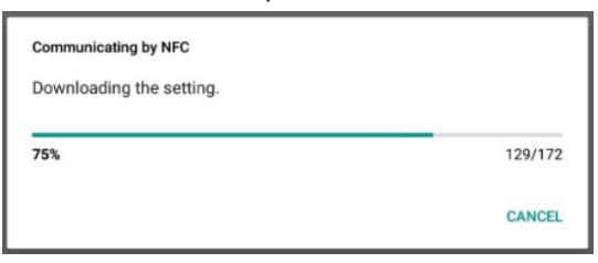
The settings will begin to download to the Android device. Continue holding device to the station until complete.
GT SETUP TOOL FOR ANDROID: EDITING SETTINGS
Step 1 Step 2
Make the necessary edits to the downloaded setting file.
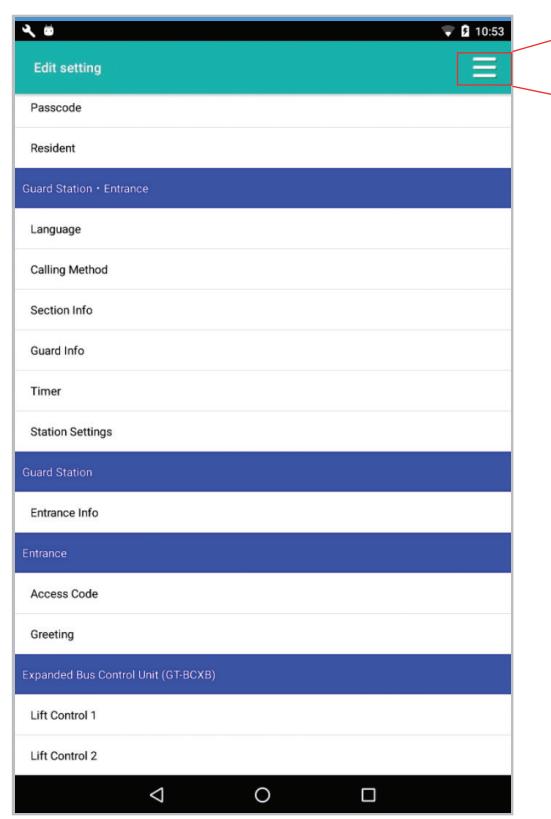
Tap the menu button, then tap Save.
Step 3
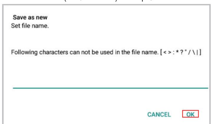
Enter a file name (i.e. Job Name) and tap OK.
GT SETUP TOOL FOR ANDROID: UPLOADING SETTINGS
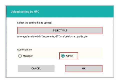
Tap UPLOAD SETTING BY NFC.
Step 1 Step 2 Step 3
Select the file to upload, tap the appropriate authorization level, then tap OK.
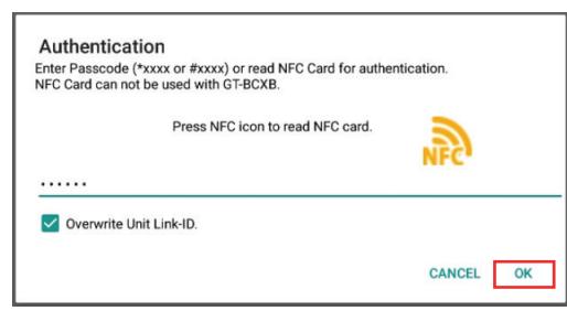
Enter the appropriate passcode (default: Admin *1111, Manager #2222). Ensure that Overwrite Unit Link-ID settings is checked, then tap OK.
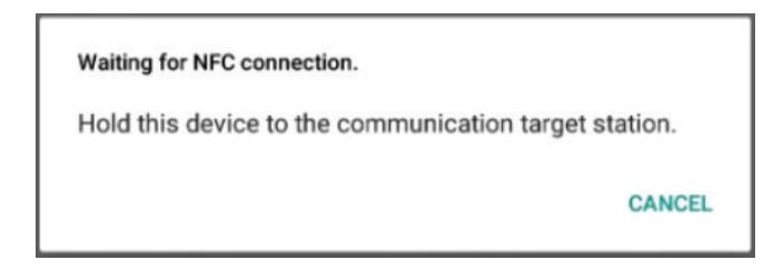
Hold the Android device to the target station to upload the settings.
Step 6
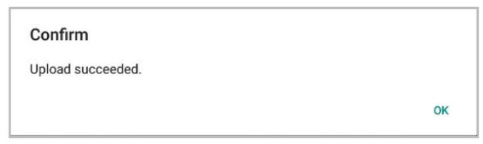
A confirmation message will appear on the Android device if the upload was successful.
Step 4 Step 5
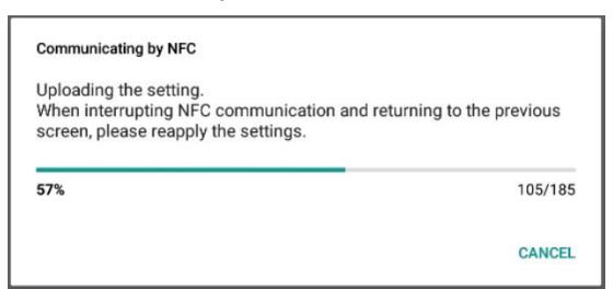
The settings will begin to upload to the target station. Continue holding device to the station until complete.
PROGRAMMING
When programming a system that includes the GT-1A or GT-1D, use the handshake method for programming all stations in the system.
PROGRAMMING: ADDRESSING TENANTS VIA HANDSHAKE METHOD
Direct Select / Push Button Entrance Station Addressing
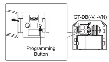
- Step 1: To enter programming mode, use a small screwdriver to push and release button under the rubber cap on the front of the GT-DB(-V, -VN) audio module. The IN USE LED will begin flashing, then remain steadily lit. Once lit, the entry panel is in programming mode.
- Step 2: At a tenant station, push and release the TALK button or pick up the handset to establish communication with the entrance station in programming mode.
- Step 3: Push and release the desired Call Button on the entrance station to assign the button to the tenant station that is active. A blip tone will be heard.
Do not press and hold the Call Button as doing so will clear the memory for this button.
- Step 4: Turn off or hang up tenant station (GT-1A/GT-1C7(-L)/GT-1M3(-L): Push TALK again, GT-2C(-L): Push OFF ).
- Step 5: Repeat steps 2-4 for remaining tenant stations.
- Step 6: To exit programming, push the button under the rubber cap on the GT-DB(-V, -VN) audio module again and the IN USE LED will turn off. The system is now ready for use.
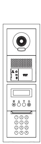
GT Digital Display Entrance Station Addressing
- Step 1: Using the GT Setup Tool for Windows, upload the program file to the GT-DB(-V, -VN) with the USB cable provided. Click then select the station to upload to and click OK .
- Step 2: To enter programming, use a small screwdriver to push and release button under the rubber cap on the front of the GT-DB(-V, -VN) audio module. The IN USE LED will begin flashing, then remain steadily lit. Once lit, the entrance station is in programming mode. The LCD will show "CONNECTING" while in programming mode.
- Step 3: At a tenant station, push and release the TALK button or pick up the handset to establish communication with the entrance station in programming mode.
- Step 4: Scroll to the station number to be programmed or manually enter the number on the keypad. When the tenant station number is displayed, push and release the Bell button to assign the address to the tenant station that is active. A blip tone will be heard.
Do not press and hold the Bell button as doing so will clear the memory for this number.
- Step 5: Turn off or hang up tenant station (GT-1A/GT-1C7(-L)/GT-1M3(-L): Press TALK again, GT-2C(-L): Press OFF ).
- Step 6: Repeat steps 3-5 for remaining tenant stations.
- Step 7: To exit programming, push the button under the rubber cap on the GT-DB(-V, -VN) audio module again and the IN USE LED will turn off. The system is now ready for use.
- Step 8: Download the program file to the GT Setup Tool from the GT-DB(-V, -VN) audio module with the USB cable provided. Click then select the station to download from and click OK .
- Step 9: Click to save the file to the computer.
PROGRAMMING: ADDRESSING TENANTS VIA HANDSHAKE METHOD (continued)
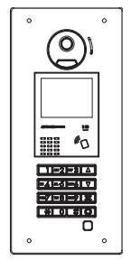
GT-DMB-N(-LVN) Entrance Station Addressing
- Step 1: Using the GT Setup Tool for Windows, upload the program file to the GT-DMB-N(-LVN) with the USB cable provided. Click then select the station to upload to and click OK .
- Step 2 : While in standby mode, enter # plus the Admin ID code (default is *1111). Re-enter ID code.
- Step 3: Use the up / down arrows and scroll to PROGRAMMING . Push the Bell button twice to enter programming mode. The IN USE LED will begin flashing, then remain steadily lit. Once lit, the entry panel is in programming mode. The LCD will show "CONNECTING" while in programming mode.
- Step 4: At a tenant station, push and release the TALK button or pick up the handset to establish communication with the entrance station in programming mode.
- Step 5: Scroll to the station number to be programmed or manually enter the number on the keypad. When the tenant station number is displayed, push and release the Bell button to assign the address to the tenant station that is active. A blip tone will be heard.
Do not press and hold the Bell button as doing so will clear the memory for this number.
- Step 6: Turn off or hang up tenant station (GT-1A/GT-1C7(-L)/GT-1M3(-L): Press TALK again, GT-2C(-L): Press OFF ).
- Step 7: Repeat steps 4-6 for the remaining tenant stations.
- Step 8: To exit programming, press the " X " button twice on the panel to return to the main menu (the IN USE LED will turn off). Scroll to QUIT and press the Bell button . The system is now ready for use.
- Step 9: Download the program file to the GT Setup Tool from the GT-DMB-N(-LVN) with the USB cable provided. Click then select the station to download from and click OK .
- Step 10: Click to save the file to the computer.
GT-MKB-N Video Guard Station Addressing
- Step 1: Using the GT Setup Tool for Windows, upload the program file to the GT-MKB-N with the USB cable provided. Click then select the station to upload to and click OK .
- Step 2: While in standby mode, press Setting. Scroll down to and press the Zoom/Wide button. ADVANCED SETTINGS
- Step 3: Use the up/down arrows and scroll to PROGRAM MODE . Press the Zoom/Wide button. Enter the Admin passcode (*1111). Re-enter the passcode again.
- Step 4: Scroll to PROGRAMMING and select PROGRAMMING again from the next screen.
- Step 5: The screen will show CONNECTING . When the orange LED on the unit remains steadily lit, the unit will be in programming mode.
- Step 6: At a tenant station, push and release the TALK button or pick up the handset to establish communication with the GT-MKB-N in programming mode.
- Step 7: Scroll to the station number to be programmed or manually enter the number on the keypad. When the tenant station number is displayed, push and release the Zoom/Wide button to assign the address to the tenant station that is active. A blip tone will be heard.
Do not press and hold the Zoom/Wide button as doing so will clear the memory for this number.
- Step 8: Turn off or hang up tenant station (GT-1A/GT-1C7(-L)/GT-1M3(-L): Press TALK again, GT-2C(-L): Press OFF ).
- Step 9: Repeat steps 6-8 for the remaining tenant stations.
- Step 10: To exit programming, press the SETTING button twice to return to the main menu. Scroll to QUIT and press the Zoom/Wide button to return to standby. The system is now ready for use.
- Step 11: Download the program file to the GT Setup Tool from the GT-DMB-N with the USB cable provided. Click then select the station to download from and click OK .
- Step 12: Click to save the file to the computer.
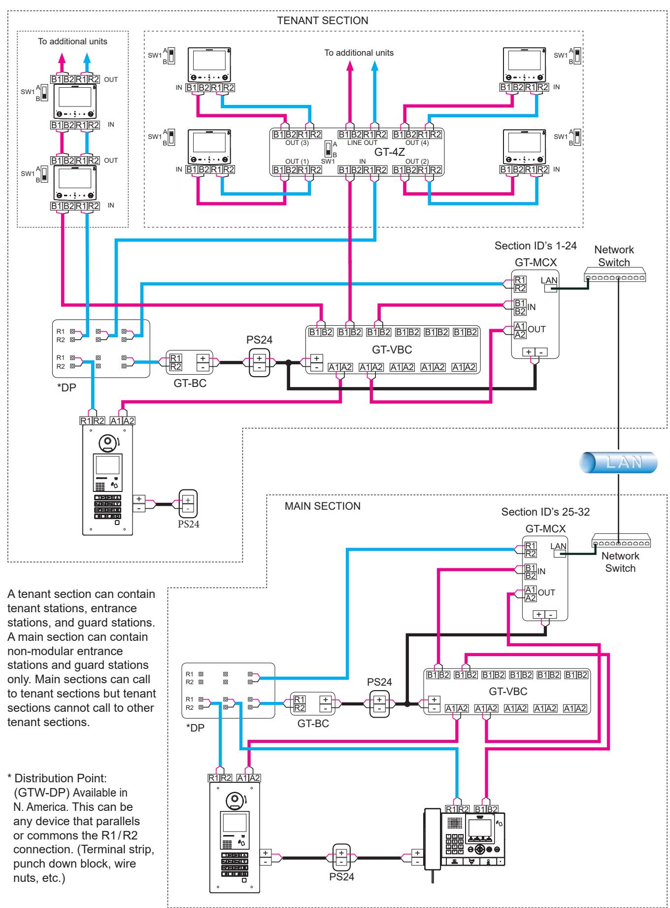
MULTI-BUILDING SYSTEM WIRING WITH GT-MCX
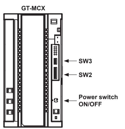
GT-MCX: Network Adaptor
The GT-MCX connects a GT system to a network, allowing the system to be remotely programmed or multiple GT systems to be tied together. When used for multiple systems, each system now becomes known as a section and requires its own GT-MCX. There are two types of sections; the tenant section and the main section. A tenant section can contain tenant stations, entrance stations, and guard stations. A main section can contain the GT-DMB(-N, -LVN) entrance stations and GT-MKB-N guard stations only.
Note: Main sections can call to tenant sections but tenant sections cannot call to other tenant sections.
DIP SWITCH SETTINGS: Tenant Section and Main Section
IMPORTANT
When the GT-MCX is included in the system, it will occupy ID#1 for both the entrance stations and guard stations. Set the entrance stations and guard stations in the system starting with ID#2. Refer to page 6 for ID settings. If the dip switches are not set correctly on the entrance stations and guard stations, you will not be able to upload any settings. The entrance stations, guard stations, and the GT-BCXB-N expansion adaptor must be set to multi-building mode when including the GT-MCX network adaptor. Set the switches as shown below per station.

Each GT-MCX must be given a unique section ID and IP address. The section ID and IP address of each GT-MCX will be determined by turning off DHCP and the SW2 dip switch setting. The IP address of the GT-MCX will be 192.168.1.50 + the ID number.
Example: 192.168.1.50 + ID 1 = 192.168.1.51
192.168.1.50 + ID 25 = 192.168.1.75
Step 1: Set SW3 dip switch 1 to ON to turn off DHCP.
| IMPORTANT | ||
|---|---|---|
| SW3 | SW3 | |
| 1234 | 1 2 3 4 | |
| (default) | (DHCP Off) |
Step 2: Set the SW2 dip switches 2-6 to the desired section ID based on the section type (see chart below).
ID's 1-24: Tenant Sections
| Dip Switch | ID | Dip Switch | ID | Dip Switch | ID | Dip Switch | ID ID |
|---|---|---|---|---|---|---|---|
| 12345678 | 1 | 12345678 | 2 | 12345678 | 3 | 12345678 | 4 |
| 12345678 | 5 | 12345678 | 6 | 12345678 | 7 | 12345678 | 8 |
| 12345678 | 9 | 12345678 | 10 | 12345678 | 11 | 12345678 | 12 |
| 12345678 | 13 | 12345678 | 14 | 12345678 | 15 | 12345678 | 16 |
| 12345678 | 17 | 12345678 | 18 | 12345678 | 19 | 12345678 | 20 |
| 12345678 | 21 | 12345678 | 22 | 12345678 | 23 | 12345678 | 24 |
| ID's 25-32: | Main Sect | ions | |||||
|---|---|---|---|---|---|---|---|
| Dip Switch | ID | Dip Switch | ı ID | Dip Switch | ID ID | Dip Switch | n ID |
| 12345678 | 25 | 12345678 | 26 | 12345678 | 27 | 12345678 | 28 |
| 12345678 | 29 | 12345678 | 30 | 12345678 | 31 | 12345678 | 32 |
Step 3: Set Power switch to ON or cycle power when done.
SYSTEM PROGRAMMING WITH MULTIPLE GT-MCX: MULTI-BUILDING
- Step 1: Open the GT Setup Tool and click the Create new site radio button. If you are already in the GT Setup Tool, click File , then select Create new site(N) .
- Step 2: Select the desired Setting authorization and select Multi building system from the Site configuration dropdown. Click Next .
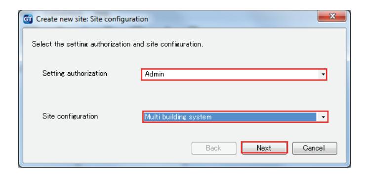
Step 3: Enter a Site Name and indicate how many Tenant Sections and Main Sections will be included by checking the box beside each GT-MCX . Select if a GT-BCXB-N is included and enter the Number of Guards and the Number of Entrances for each section. The GT-MCX will take the place of the Guard Station ID1 and Entrance Station ID1.
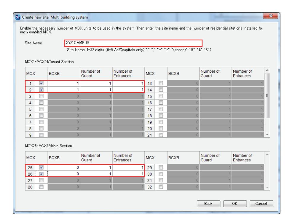
Step 4: Click OK .
A system will be created within the GT Setup Tool that will include the number of GT-MCX network adaptors selected and the number of guard stations and entrance stations selected for each.
SYSTEM PROGRAMMING WITH MULTIPLE GT-MCX: MULTI-BUILDING (cont.)
Step 5: Select the first MCX in the system, then click Section Info. Enter a Section #, a Section Name, and IP Address for each GT-MCX in the system based on what was selected in Step 3. Ensure that tenant sections are entered in lines 1-24 and Main Sections are entered in lines 25-32. Click Save when done.
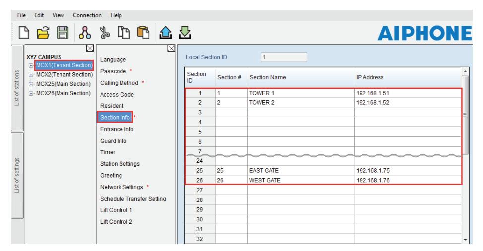
Step 6: Repeat step 5 for each MCX in the system. Copy/Paste (Ctrl C, Ctrl V) from the first MCX Section Info to other sections can be used to save time.
Note: If programming a multi-building system with more than 500 tenants, ensure that the Calling Method is set to either Section List + Unit# , Section# + Unit# , or Unit Number in the Main Section.
PROGRAMMING: ADDRESSING TENANTS VIA DIP SWITCH METHOD
Step 1: Create an ID correlation table for the tenant stations using the binary / SW2 Dip Switch - ID chart. The chart below is for the first 48 stations in a non-expanded or expanded system. The full Dip Switch chart can be downloaded from http://www.aiphone.net/product/support/gt/ Standard system = S1 - S48. Expanded system = A1 - A250 & B251 - B500
| Dip Switch | ID |
|---|---|
| S1/A1 | |
| S2/A2 | |
| S3/A3 | |
| S4/A4 | |
| S5/A5 | |
| S6/A6 | |
| S7/A7 | |
| S8/A8 | |
| S9/A9 | |
| S10/A10 | |
| S11/A11 | |
| S12/A12 |
| Dip Switch | ID |
|---|---|
| S13/A13 | |
| S14/A14 | |
| S15/A15 | |
| S16/A16 | |
| S17/A17 | |
| S18/A18 | |
| S19/A19 | |
| S20/A20 | |
| S21/A21 | |
| S22/A22 | |
| S23/A23 | |
| S24/A24 |
| ID |
|---|
| S25/A25 |
| S26/A26 |
| S27/A27 |
| S28/A28 |
| S29/A29 |
| S30/A30 |
| S31/A31 |
| S32/A32 |
| S33/A33 |
| S34/A34 |
| S35/A35 |
| S36/A36 |
| S37/A37 |
|---|
| S38/A38 |
| S39/A39 |
| S40/A40 |
| S41/A41 |
| S42/A42 |
| S43/A43 |
| S44/A44 |
| S45/A45 |
| S46/A46 |
| S47/A47 |
| S48/A48 |
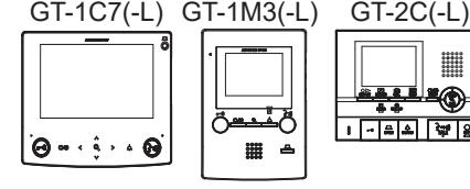
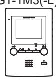
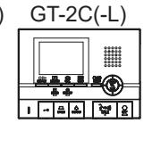
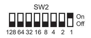
Step 2: Set the SW2 dip switches found on the back of the GT-1C7(-L), GT-1M3(-L), and GT-2C(-L) according to the correlation table created in the previous step.
PROGRAMMING: ENTERING RESIDENT INFO
Resident information must be entered into the GT-MCX, GT-DMB(-N, -LVN), GT-MKB-N, and modular digital entrance stations before tenant stations can be programmed.
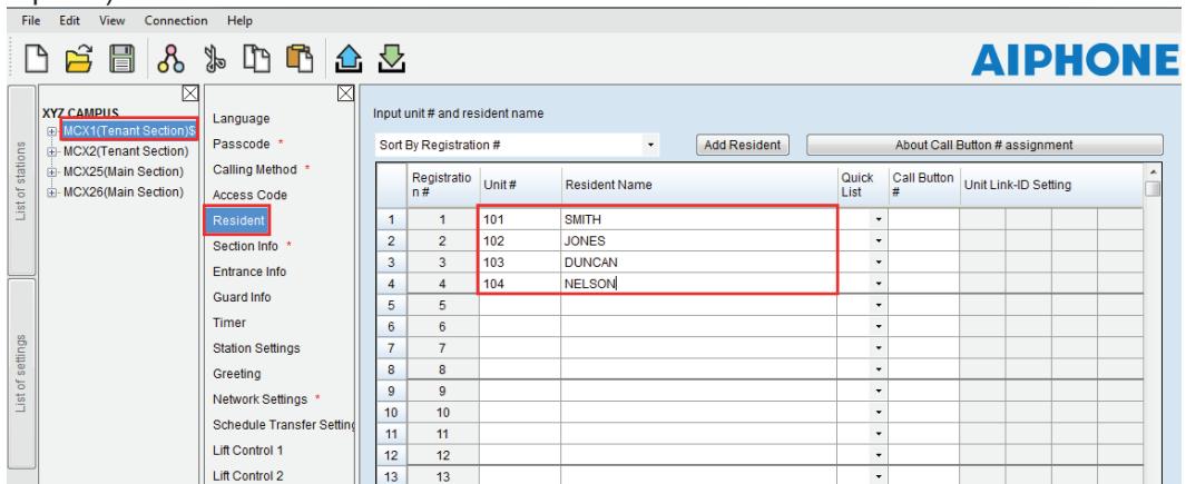
Step 1: Click MCX1(Tenant Section) and then click Resident . Enter a Unit # (required) and a Resident Name (not required) for each station in this section.
- Step 2: Click Save , and then Yes .
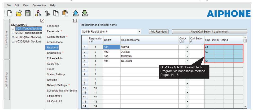
- Step 3: Enter a Unit Link-ID Setting for each station based on the correlation table on page 19.
- Step 4: Click Save , and then Yes .
- Step 5: Repeat Steps 1-4 for each MCX(Tenant Section) in the system. Ensure that each MCX is programmed with a unique Unit # for each tenant.
Example: MCX1 Unit # = 101, 102, 103, etc. MCX2 Unit # = 201, 202, 203, etc.
Step 5: The unique resident information created for each Tenant Section will need to be copied to each Main Section in the system. Use Copy /Paste (Ctrl C, Ctrl V) when copying the data. When copying to the Main Sections, do not overwrite the resident info copied from Tenant Section 1 when copying the resident info from Tenant Section 2.
Example of resident info in a MCX(Main): Tenant Section 1 resident info = lines 1-4 Tenant Section 2 resident info = lines 5-8
Note: If programming a multi-building system with more than 500 tenants, ensure that the Calling Method is set to either Section List + Unit# , Section# + Unit# , or Unit Number in the Main Section. When set to these calling methods, resident information is not required in a Main Section when more than 500 tenants are being called. Tenants must be called via station number only.
PROGRAMMING: ENTERING ENTRANCE STATION AND GUARD STATION INFORMATION
Programming Entrance/Guard Information
Step 1: Click the MCX1(Tenant Section) , then select Entrance Info . Enter the Section ID , Entrance ID (2-16), Entrance #, and Entrance Name (not required) for each entrance station in the system. Ensure that the Section ID is correct in relation to which section the entrance station resides.
The GT-MCX uses Entrance ID 1 for each section.
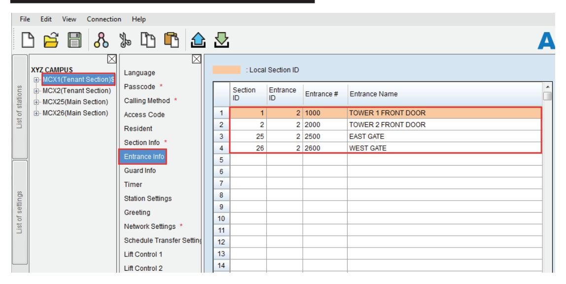
Step 2: Click Guard Info . Enter the Section ID , Guard ID (2-4), Guard #, and Guard Name (not required) for each guard station in the system. Ensure that the Section ID is correct in relation to which section the guard station resides.
The GT-MCX uses Guard ID 1 for each section.
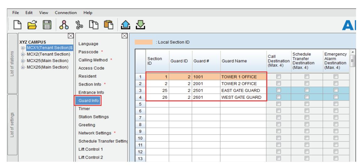
- Step 3: Click Save , and then Yes .
- Step 4: Copy the Entrance Info and Guard Info from MCX1(Tenant Section) to each of the MCX's in the system. Use Copy/Paste (Ctrl C, Ctrl V) to save time.
PROGRAMMING: TRANSFER DATA TO ENTRANCE STATIONS AND GUARD STATIONS
Compare and Merge (copy data to other stations in a section)
Warning: Do not Compare and Merge Settings between MCX Sections.
- Step 1: Click Compare and Merge Settings to copy data from the MCX to entrance stations and guard stations within the same section.
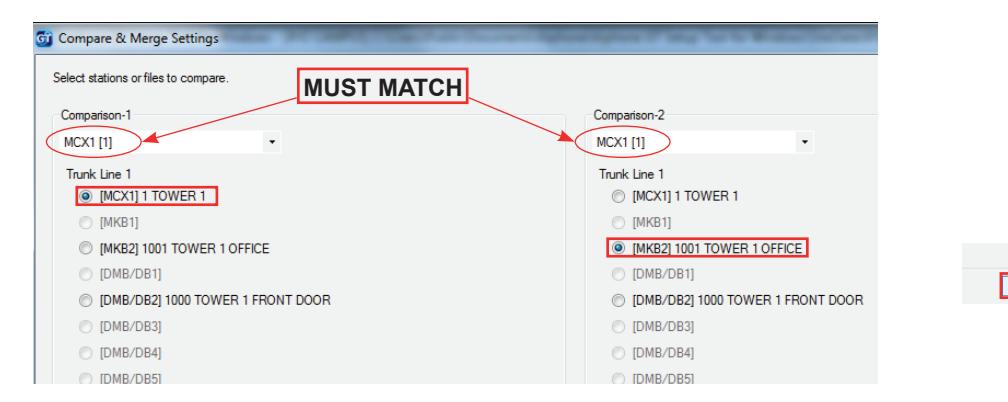
- Step 2: Ensure that the drop down under Comparison-1 and Comparison-2 have the same section selected. Important: To prevent duplicate IP addresses, do not Compare/Merge settings between MCX adaptors. In the Comparison-1 column, select the MCX1 radio button that was fully programmed. In the Comparison-2 column, select the desired entrance station/guard station that you want to copy the data to. Click Compare .
Step 3: Click Copy All Settings , then click Comparison-1 >> Comparison-2 to copy the data to the new station. In the Do you want to overwrite all of the data? popup, click Yes . Enter the Admin Passcode (default is *1111) for the device being copied to. Click OK. When done, click Save, then Yes .

- Step 4: Click Select comparison to return to the compare and merge screen and repeat for each entrance station and guard station in this section.
- Step 5: Repeat steps 2-4 for each MCX(Tenant/Main section). When done copying all settings to each station in each section, click Exit to return to the main programming screen.
PROGRAMMING: UPLOADING TO GT-MCX VIA LAN
- Step 1: Click Upload .
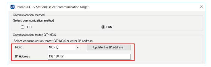
- Step 2: From the Upload menu, select the LAN radio button.
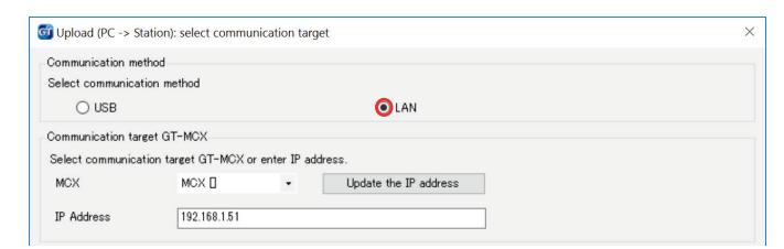
Step 3: Select the desired GT-MCX and verify the correct IP address .
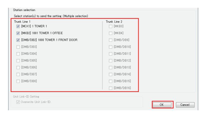
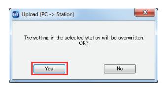
Step 4: Select each station that you wish to upload the setting file to. Multiple stations can be selected at the same time. Click OK . Click Yes in the popup window asking if it's ok to overwrite the selected stations.
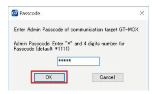
Step 5: Enter the Admin / Manager Passcode and click OK . The default Admin Passcode is *1111.
Note:
If the upload to the stations does not work, check the following:
- 1. Ensure that the entrance station and guard station ID settings are correct. Duplicates on like stations within a section and ID#1 cannot be used.
- 2. Check that the GT-BC and GT-MCX are connected and powered on.
- 3. Check that the NIC setting for the GT Support Tool is set correctly. Check this under Connection > Network Interface Card: NIC
- 4. Ensure that you can ping the GT-MCX from your PC.
PROGRAMMING: SHARING HANDSHAKE DATA
The handshake programming method can be used within a Tenant Section only. The handshake is a correlation between the tenant and an entrance station or guard station. In order for the Main Section to call a tenant station that was programmed via handshake in the Tenant Section, the link ID will need to be shared between the entrance/guard station that was programmed and the Tenant Section MCX.
After completing the handshake process on pages 14-15 for the tenant stations, download the data from the entrance station or guard station that was programmed for those stations.
- Step 1: Click Download .
- Step 2: From the Download menu, select the LAN radio button. Select the Tenant Section MCX where the entrance/guard station programmed with handshake data resides. Verify the IP address is correct.
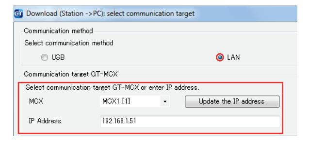
Step 3: Select the entrance/guard station that was programmed with the handshake data. Click OK . Click Yes in the popup window asking if it's ok to overwrite the data. Enter the Admin Passcode and click OK . The default Admin Passcode is *1111.
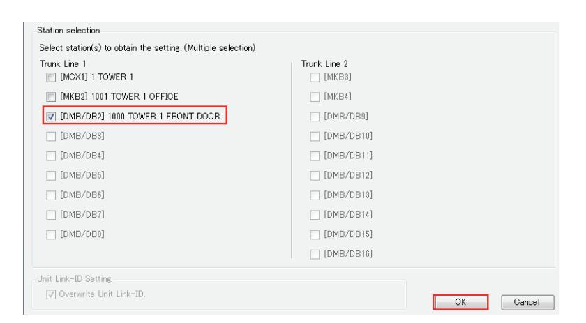
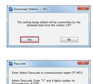
- Step 4: Copy/paste (Ctrl C, Ctrl V) or use Compare and Merge Settings (page 22) to send the newly downloaded resident data from the downloaded entrance/guard station to the Tenant Section MCX and other entrance/guard stations in this section.
- Step 5: After all data has been copy/pasted or Compare and Merged to the MCX and each entrance/guard station in this section, Upload settings to all stations in this section again (see page 23).
- Step 6: Repeat steps 1 5 for each tenant section in the system.