Aiphone NHX System Installation Manual
Open the original PDF document
View PDF

HEALTH CARE COMMUNICATION SYSTEM for Nursing Homes & Health Care Facilities
NHX SYSTEM
INSTALLATION MANUAL
CONTENTS
| Pı | recautions on Installation & Wiring | 3 |
|---|---|---|
| 1 | System Outline & Components | 4 - 7 |
| System Outline | 4 - 5 | |
| Components available | 6 - 7 | |
| 2 | Names & Features | 8 - 12 |
| • Names | 8 - 11 | |
| System Features | 12 | |
| System Capabilities | ||
| 3 | Installation & Wiring | 13 - 21 |
|
||
| • Power off system resetting • Zone light installation | 13 | |
| • Setting Station #1 ~ 10 on Sub stations | ||
| • Initializing NHX-80X for Sub stations | ||
|
||
| Terminal block layout | ||
| Wiring diagrams | ||
| 4 | Mounting | 24 - 27 |
| 5 | _ | |
| 6 | Technical Precautions | |
| Specifications |
This Manual is supplied with the NHX-80X Central Control Unit.
Prior to installation of NHX system, the contents of this Manual must be thoroughly read and understood. The Operation Manual is supplied with the NHX-50M master station.
PRECAUTIONS ON INSTALLATION & WIRING
: WARNING
(Negligence could result in death or serious injury)
: PRECAUTIONS
(Negligence could result in injury or damage to property)
: GENERAL PRECAUTIONS.
: Prohibitions to dismantle equipment.
: Prohibitions to subject the equipment to water.
: Take the unit to earth ground.
WARNING
- 1. Do not connect a power supply other than Aiphone Model PS-24E or PS-2420 to terminals +, – on NHX-80X. Doing so can cause fire or damage to the unit.
- 2. Do not change or modify NHX equipment.
- 3. The NHX equipment must not be exposed to water or any other liquid.
- 4. Do not open NHX-80X without first unplugging power supply(ies) to prevent electric shock.
- 5. Make sure wires are connected properly before plugging in the power supply(ies).
- 6. Keep AC cord free from being pulled or crushed.
- 7. Do not plug or unplug with wet hands.
- 8. Keep AC outlet away from moisture and dust.
PRECAUTIONS
- 1. Mount the NHX-80X unit on wall in a convenient location, but not where it could be bumped or jarred.
-
2. Do not install NHX components in any of the following locations, as it may cause the system to malfunction;
- High or extreme cold temperature area: under direct sunlight, near equipment that varies in temperature, in front of air-conditioner, inside a refrigerated area, etc.
- Places subject to moisture or humidity extremes.
- Places subject to environmental conditions, such as oil, dust, chemicals, salt, etc.
- Places subject to constant vibration or impact.
- 3. Take to earth ground every bed of metal pipe construction to protect Bedside sub stations and hand-held call buttons from ESD(Electrostatic discharge).
GENERAL PRECAUTIONS
- 1. NHX system is not operable during a power failure.
- 2. In areas where broadcasting station antennas are close by, NHX intercom system may be affected by radio frequency interference.
- 3. Keep all DC wiring at least 30cm, 20" away from AC100~240V wiring, fluorescent lighting, or dimmer switches. Cross AC wiring at a 90° angle.
- 4. Do not connect any devices other than the Aiphone Models covered in this Manual.
Markings
In accordance with CSA C22.2 No.125-M1984, the 4th Edition Standard, For Electromedical Equipment the following NHX Series units are provided with the "Risque class1 Part" (and in French- "Risque La Pièce class1") marking.
Model NH-1SA, and -2SA, -1SA/A, -2SA/A Patient Stations;
Model NHR-7A, Bath Pull-Cord Stations;
Model NHR-8A, Call Cord
1 SYSTEM OUTLINE & COMPONENTS
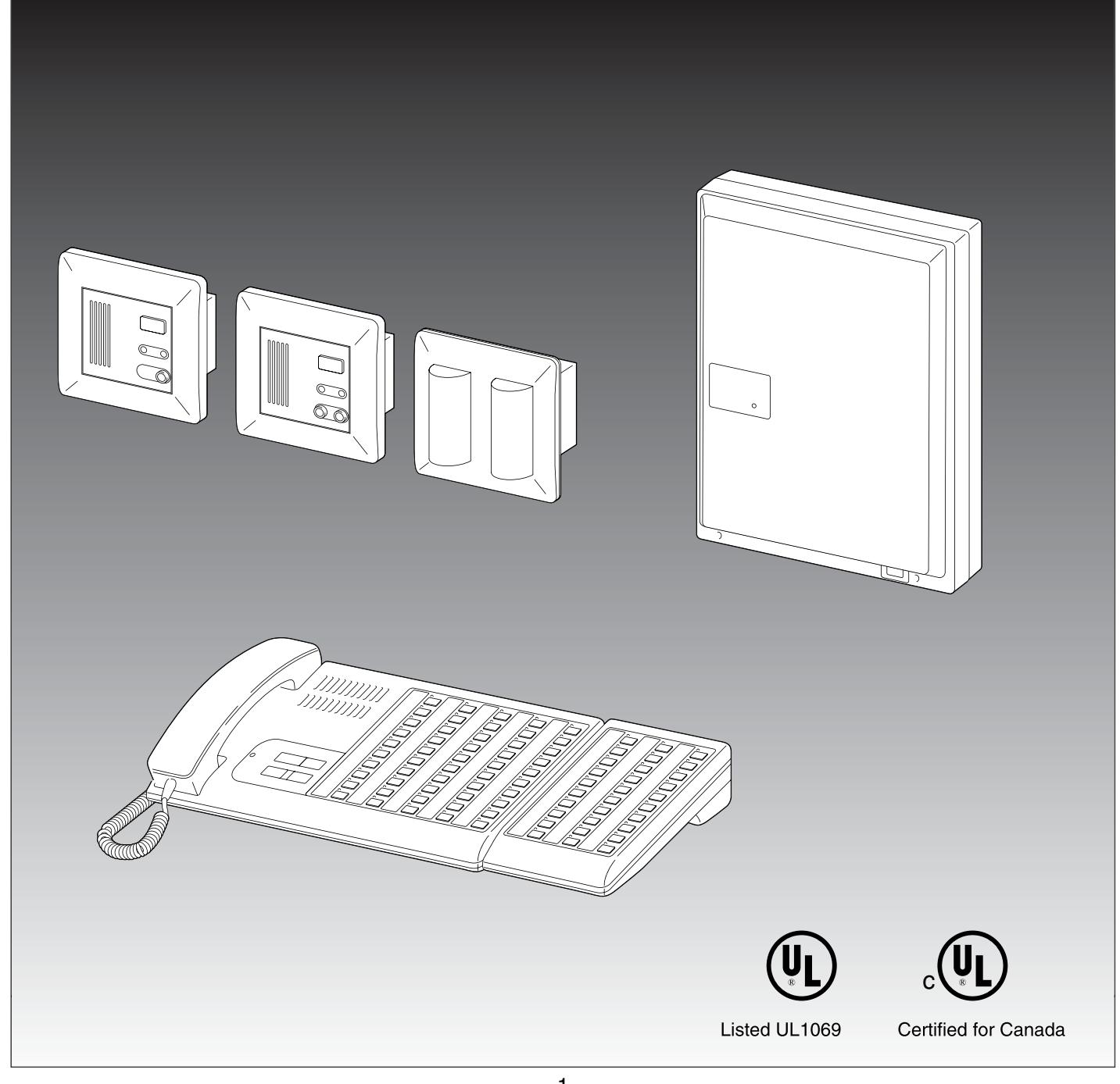
The NHX is a Health Care Communication System, exclusively designed for patient to staff communications in health care facilities. The NHX system is UL Listed under UL1069 the Standard for Hospital Signalling & Nurse Call Equipment. At Nurses Center, the NHX-50M master station is an extremely compact, low profile console. Add-on 30-call selector can be plugged into NHX-50M. In each room, single or dual-call Nurse Call bedside sub stations are used with corridor light and bathroom call switch. The NHR-3TS is a common area or hallway sub station, which can be used with a NHR-7A pullcord urgent call switch.
- Package Contents
- Central Control Unit (NHX-80X)
- Packet of screws
- Installation Manual
- Replacement 3A Fuse (2) (attached inside back case)
SYSTEM OUTLINE
1. Up to 8 Sub trunk lines (10 rooms each).
Failure on one line does not affect the other trunk lines.
- Optional conduit wiring through junction boxes.
- Max. 10 sub stations in parallel per block.
- Programming # on each sub.
- Sub station may have urgent bathroom call button (ea. 3 wires).
- Corridor light mounted on 1-gang box (3 wires).
- Gang box may be used for junction of 3P Trunk cable.
2. NHX-80X Central Control Unit.
50 or 80-call station capacity.
- CCU wall-mounts on 3-gang box or inside electrical enclosure (both UL Listed).
- Install NHR-30K, 30-call add-on Trunk Card in the NHX-80X.
3. Compact 50-call Master Station.
- 30-call add-on selector plugs in and connects with bracket.
- Max. 4 Zone lights, ceiling or wall mount. With any type of call, light comes on to indicate the calling zone. One separate PS-24E or PS-2420 required for 2 Zone lights.
- Duty station (NHR-SP) annunciates call tone, with TONE OFF button.
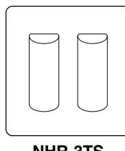
4. NHR-3TS Bathroom call sub station places an urgent call.
- NHR-3TS contains sub station circuitry.
- May be used in two ways: one as common area bathroom call sub station(2 red lights) used with NHR-7A bathroom pullcord, the other as hallway staff call sub station (one white lamp used) used with the same NHR-7A call switch.
5. Bedside sub station NH-1SA/A and NH-2SA/A for multiple installation within a patient room.
- Max. 6 bedside sub stations within a patient room.
- Single and common bathroom call switch.
- Single or two corridor light installation.
COMPONENTS AVAILABLE
- Central Control Unit Urgent bathroom call sub station (common area)
- Bedside sub stations


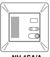
NHR-3TS NH-1SA/A NH-1SA
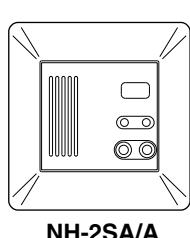
NH-2SA/A NH-2SA
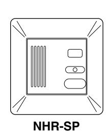
• Master station & Add-on selector • Duty station

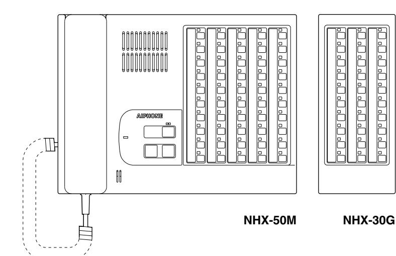
• Central Control Unit NHX-80X: Central Control Unit(CCU) w/50 or 80 station capacity.
• Master station NHX-50M: 50-call master console.
NHX-30G: 30-call add-on selector, plug-in connector.
• Duty station NHR-SP: Duty station. Call tone receiver. • Bedside sub stations NH-1SA/A, NH-1SA: Single-call sub station. NH-2SA/A, NH-2SA: Dual-call sub station.
• Corridor lamp (sub) NHR-3TS: Common area call station, used w/NHR-7A Bathroom pullcord.
NHR-3TS: Urgent staff call sub station, used w/NHR-7A mechanical lock switch
in the hallway.
• Power supply PS-24E or PS-2420: AC 120V. DC24V, 2A. 2 required for NHX-80X only.
One separate PS-24E or PS-2420 required for two Zone lights.
• 30-call add-on trunk card NHR-30K: XC-461 Card complete with mounting accessories for system
expansion to 80 stations.
Accessories: Aiphone Models & UL Listed locally available
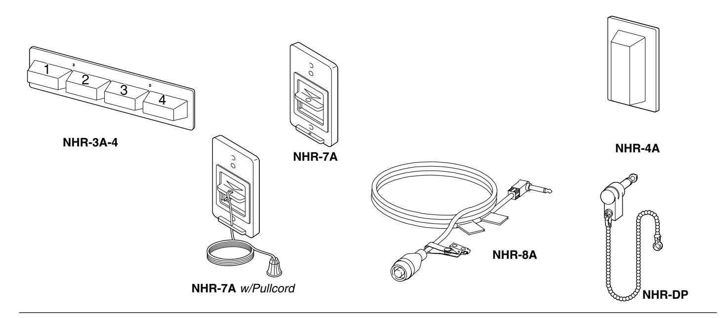
• Zone light 4-zone indicator light. Max. 4 units.
(NHR-3A-4) Up to 2 units powered by a PS-24E or PS-2420 power supply.
• Urgent call switch Provides dry closure contact, with mechanically latching switch.
(NHR-7A) Master-RING LED is lit.
Used with bedside sub station, or NHR-3TS corridor lamp in common area for urgent bathroom call, or in the hallway for urgent staff call. Urgent call switch
cannot be used alone.
Contact Ratings; DC 24V, 10mA to max. 20mA (min. 5mA or more).
(NHR-8A)
• Hand-held call cord Provides dry closure contact with 1/4" phone plug.
• Corridor lamp Connected to each. Bedside sub station.
(NHR-4A) Two lamps (red & white). Ratings; 24V, 100mA.
(NHR-DP)
• Dummy plug Plugs into jack unused on bedside sub stations.
2 NAMES & FEATURES -
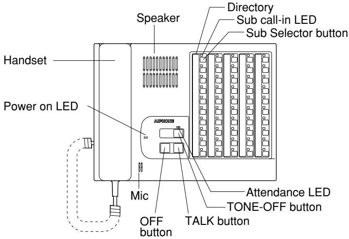
■ NHX-50M
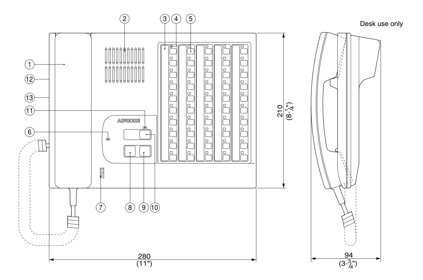
NHX-50M
- 1. Handset
- 2. Speaker
- 3. Directory
- 4. Sub call-in LED
- 5. Sub selector button
- 6. Power on LED
- 7. Mic.
- 8. OFF button
- 9. TALK button
- 10. TONE-OFF button
- 11. Attendance LED
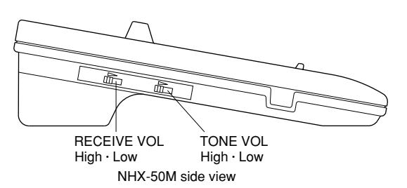
- 12. RECEIVE VOL.
- 13. TONE VOL. See OPERATIONS section.
■ NHX-30G
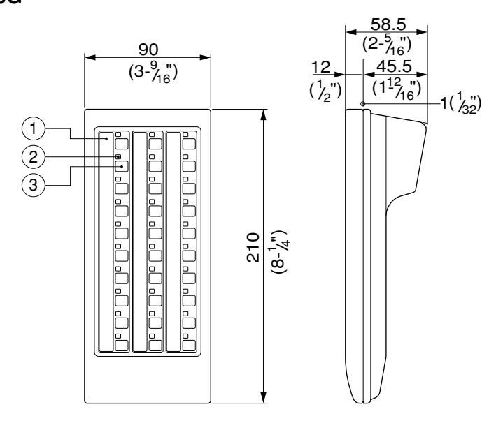
NHX-30G
- 1. Directory
- 2. Sub call-in LED
- 3. Sub selector button
■ NH-1SA/A
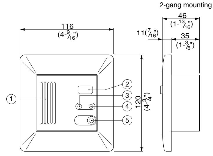
Speaker/mic.
2. CANCEL button (for routine call only)
3. TALK mode LED
4. Master-RING LED (CALL)
5. Jack (1) for CALL button
CANCEL button: Cancels a routine call only, while the bathroom and cord-out trouble call can be cancelled at the site.
■ NH-2SA/A

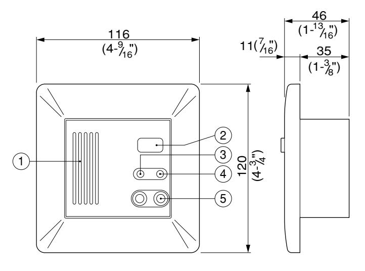
- 1. Speaker/mic.
- 2. CANCEL button (for Routine call only)
- 3. TALK mode LED
- 4. Master-RING LED (CALL)
- 5. Jacks(2) for CALL button
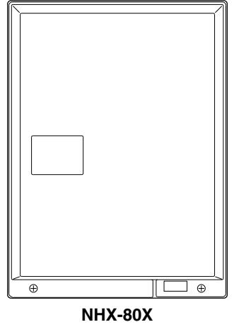
■ NHX-80X
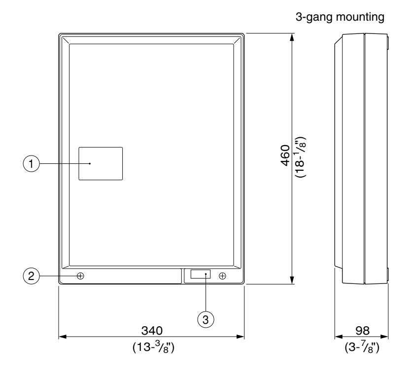
- Power on LED, green Front cover screw (2)
- 3. Power switch
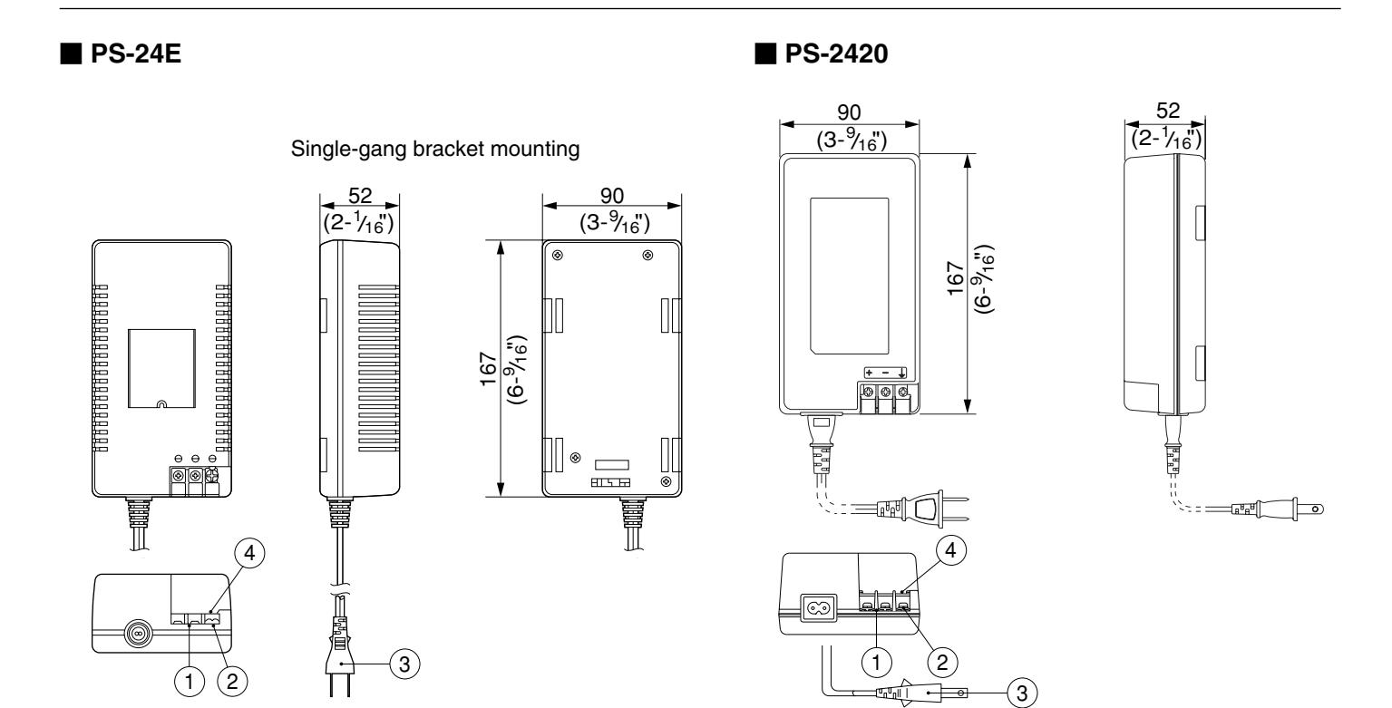
- 1. 24V DC output terminals
- 2. Terminal for grounding
- 3. 120V AC input power cord & plug of approx. 6'3"(1.9m) long
- 4. Cover of Terminal section
■ NHR-3TS
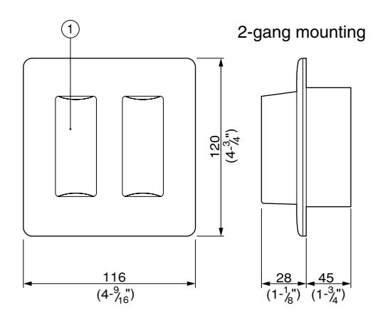
1. Lamp cover (2) Red lamps inside
■ NHR-4A
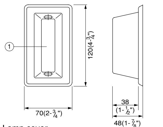
1. Lamp cover White & red lamps inside
■ NHR-SP
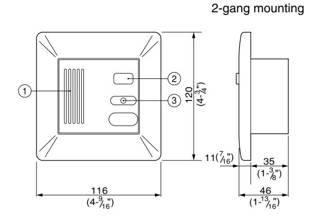
- 1. Speaker
- 2. TONE-OFF button
- 3. Master-RING LED (CALL)
■ NHR-7A
Single-gang mounting
Single-gang mounting
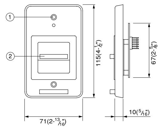
- 1. Master-RING LED
- 2. Pull-lock switch Tie up the pullcord supplied
■ NHR-3A-4
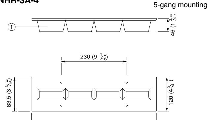
438 (17- 1/4")
- 1. Lamp cover (4) Red lamps inside
- 2. 5-gang mounting holes
■ NHR-8A
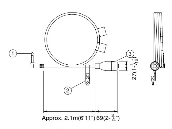
- 1. Plug
- 2. Clip
- 3. Call button
System Features
- 1. Listed UL1069 Patient to Staff Communication System for up to 80 stations.
- 2. Voice-actuated handset or press-to-talk communication. Single and private channel (cannot be broken into).
- 3. Up to 8 trunk lines for subs. Max. 10 sub stations per trunk line. 3 twisted pair looped wiring, plus one separate wire for zone light indicator.
- 4. Compact sized 50-call master station. 30-call add-on selector simply plugs into master. (Expansion card required for CCU)
- 5. Single or dual-call Nurse Call bedside sub stations, able to have multiple stations in one room with common bathroom pullcord and corridor lamp.
- 6. NHR-3TS Bathroom/Hallway urgent call sub station used with NHR-7A pullcord or switch.
- 7. Listed UL 1069 components: Corridor lamps, Bathroom pullcords, urgent call switches, and Zone lights.
-
8. Three types of calls with distinct tone and light signalling.
- 1) Routine Call
- 2) Urgent Call- from bathroom common area bath or urgent call station
- 3) Cord-out trouble call from bedside.
- Calls are answered in order of urgency and time of call.
- 9. Call tone & LED annunciation at Duty station.
- 10. Station number programming on each Sub station.
- 11. Sub stations connection verification at NHX-50M Master station.
- 12. Line-off trouble sounds intermittent buzzer with LED illumination.
- 13. Plug in wire terminations at Master and Sub stations. Makes replacement easy.
System capabilities
- 1. A call from dual-call bedside sub (NH-2SA/A) lights the same call-in LED on the NHX-50M or NHX-30G.
- 2. NHX-50M master holds max. five call-in LED's simultaneously.
-
3. The following features are not included in the NHX system;
- Second master in parallel (for routing calls). Ceiling mount sub
- Desk or hand-held sub. Call extension speaker
- Communication with 2 or more subs at a time. Background music
- All call
3 INSTALLATION & WIRING
Mounting location
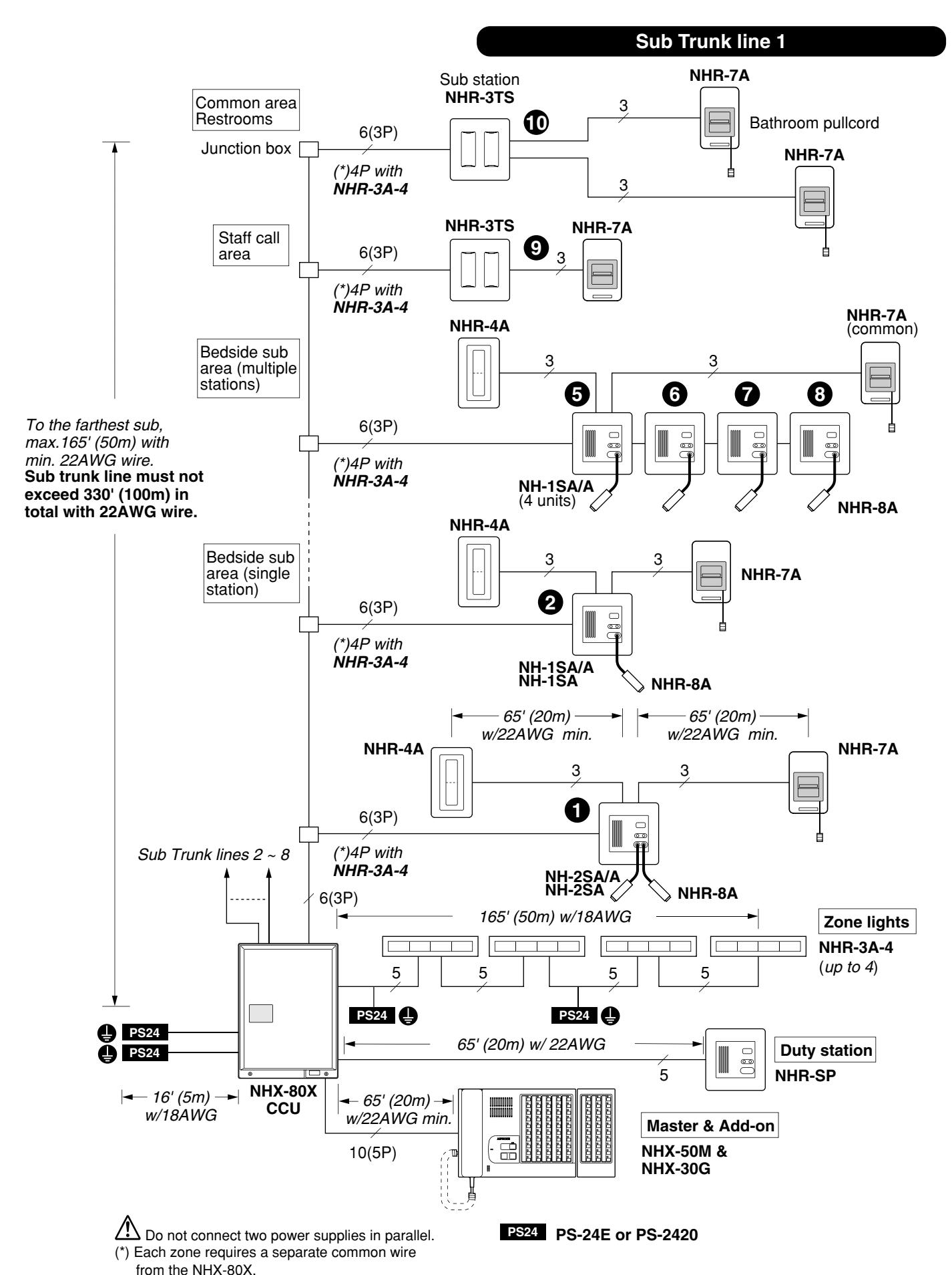
NHX equipment is designed for indoor use only. NHX-80X must be wall-mounted on a UL Listed 3-gang box or in a Listed electrical enclosure. The enclosure should be provided with a solid noncombustible mounting plate board for securing the NHX-80X chassis. ( Ref. NHX-80X dimensions: 460H x 340W x 98D. 18-1/8"H x 13-3/8"W x 3-7/8"D). Locate the NHX-50M master within close proximity of the NHX-80X CCU. (Max. 20m, 65' wiring distance)
Wiring
- 1. Use Aiphone specified shielded cable. Otherwise, run wires in metal conduit to prevent any malfunction or noise interference.
- 2. CAUTION: Risk of Electric Shock When installing, route field wiring away from sharp projections, corners, and internal components.
Cable
For wiring between NHX-80X, NHX-50M, and sub stations, use UL Listed twisted pair cable, only copper conductors, 22AWG min. or heavier, rated 300V. Cable to call buttons and lamps can be either parallel or twisted pair cable, 22AWG or heavier, UL Listed.
Power supply
For NHX-80X CCU, use the power supply exclusively designed, as listed below;
• PS-24E or PS-2420: Rated input 120V AC, 50/60Hz. Rated output: DC 24V, 2A (Requires two units per system).
For Zone light Model NHR-3A-4 (max. 4 per system), install a PS-24E or PS-2420 power supply for every 2 Zone lights.
Power off system resetting
When NHX system malfunctions, turn NHX-80X power switch off and on again, and entire system will be reinitialized. The reset switch on NHX-80X is used when initializing NHX-80X for sub stations. The reset switch on NHX-50M is used when checking connection of sub stations.
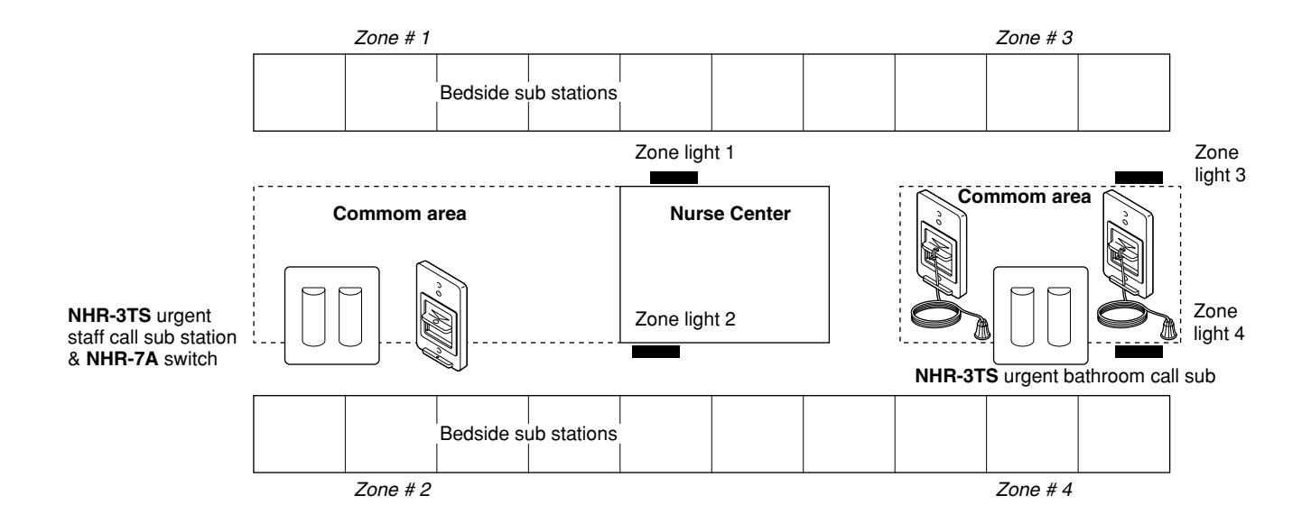
Zone light installation
Zone light will indicate which zone has a call placed at one to max. 4 locations in the facility.
• Permitted distance: 165' with 18AWG (50m with 1.0mmø) from the NHX-80X.
■ Setting Station #1 ~ 10 on Sub stations
Before installing sub stations:
- 1. Make a SUB STATION # CHART (Fig. 2), assigning sub station numbers to each room where sub will be installed.
- 2. Move 4 dip switches (1 ~ 4) on the back of the sub station according to the # chart.
• NHX-50M master station
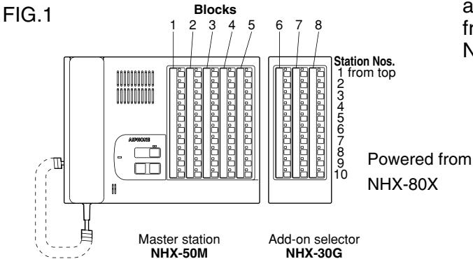
As shown in Fig. 1, the vertical rows of Call buttons are assigned sub station (from top) of Trunks 1 - 5 from the left on NHX-50M.
NHX-30G controls Trunks 6 ~ 8.
Sub stations
Sub # Set switches: Initially all in OFF position. Move to upper ON position, according to the Chart.
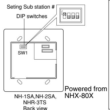
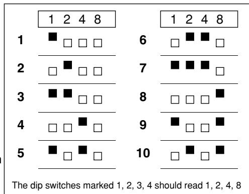
Example: #7:1+2+4=7
* Do not assign the same number for more than one sub within a trunk. Otherwise, system will malfunction.
FIG. 2 Example: Sub station # Chart
| Sub's Block | Туре | of Subs | Block # | Subs # |
Bathroom
Pullcord |
Corridor lamp |
Urgent
Call Sw. |
Zone # |
|---|---|---|---|---|---|---|---|---|
| & Number | Bedside | Toilet | Block # | Subs π | Yes or No | Yes or No | Yes or No | Assigned |
| BLOCK 1-1 | 0 | 1 | 1 | 0 | 0 | 1 | ||
| 2 | 2 | 0 | 0 | |||||
| 3 | 3 | 0 | 0 | |||||
| 4 | Ō | 4 | Ō | Ō | ||||
| 5 | 0 | 5 | Ö | 0 | ||||
| 6 | 0 | 6 | ||||||
| 7 | 0 | / | ||||||
| 8 9 | 00 | 8 9 | ||||||
| 10 | 0 | 0 | 10 | (NHR-3TS own) | (Staff call) | |||
| BLOCK 1-1 | 2 | 1 | , | 2 | ||||
| 2 | 2 | |||||||
| BLOCK 8-1 | 0 | 8 | 1 | 0 | 4 | |||
| 2 | Ŏ | 2 | Ŏ | |||||
| 3 | 3 | 0 | ||||||
| 4 | 4 | 0 | ||||||
| 5 | 5 | |||||||
| 6 | 0 | 6 | O O | |||||
| 7 | 0 | 7 | ||||||
| 8 | 0 | 8 | ||||||
| 9 | 9 | ( ) ( ) ( ) ( ) ( ) ( ) | ||||||
| 10 | 10 | I | (NHR-3TS own) |
Zone # 1 4: Assigned by wire terminations of Sub's ZL terminal. Corresponding terminals are Z1 - Z4 on NHX-80X).
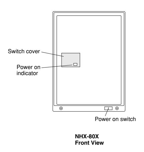
Inside the cover, are located dip switches SW2-1~4, RESET switch and four LED's.
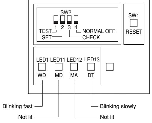
In standby, the status of the LED's are as above.
Initializing NHX-80X for Sub stations
The NHX-80X CCU must be set to zero after all the sub station numbers are programmed. Proceed as follows;
- 1. Remove the switch cover on front cover. Place the dip switch SW2-2(SET) to upper ON position. The rest dip switches must remain in OFF position.
- 2. Make sure sub stations are all in standby. If a sub is not in standby mode, it cannot be acknowledged properly.
- 3. Turn power switch on NHX-80X ON.
- 4. Press RESET switch. LED 1 blinks green.
- 5. LED13 blinks green for 5 seconds, and goes out.
- 6. Place the dip switch SW2-2(SET) back to OFF position.
- 7. Press RESET switch again. Programming for subs is complete. All the switches must be in OFF position. LED13 starts blinking. See the status of four LED's as above.
Checking Status of Sub stations on NHX-50M (Testing)
Test the NHX-50M to visually check status of all sub stations:
-
On the bottom of the NHX-50M, press RESET button while holding down OFF button on front panel. The NHX-50M enters testing mode. Check the sub stations throughout system as follows:
- From sub 1 of the first row, the LED is lit and goes out if the sub is connected.
- Then, the LED of sub 2 is lit and goes out. All subs are scanned in this way to check sub's status. If a sub is not connected, the LED is lit and remains on.
- If a sub is connected but the LED won't go out, check status of the sub station as follows:
- (1) Incorrect programming
- (2) Not placed in standby with bathroom call
- (3) Incorrect wire terminations
- On the subs(s), which have been found yet not programmed in testing mode, check number programming. Repeat process from Step 4 of the above section.
- To get out of testing mode, press OFF button on NHX-50M.
Terminal block layout
• NHX-80X
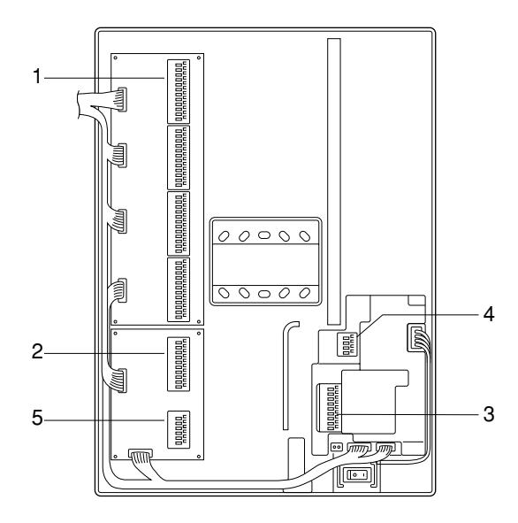
1. Subs trunk lines
11 ~ 16: for Block 1 21 ~ 26: for Block 2 31 ~ 36: for Block 3 41 ~ 46: for Block 4 51 ~ 56: for Block 5 61 ~ 66: for Block 6 71 ~ 76: for Block 7 81 ~ 86: for Block 8
1, 2: Voice 3: + 24V 4: GND 5: DATA + 6: DATA –
2. NHX-50M master
M1: +24V M2: GND M3: DATA 1 M4: DATA 2 M5: Voice M6: Voice
M7: Duty station connection M8: Duty station call tone. M9: Duty station call control M10: Duty station LED control
3. Zone light connection
(to sub's ZL terminal)
Z1: to Subs of zone 1 Z2: to Subs of zone 2 Z3: to Subs of zone 3 Z4: to Subs of zone 4
* A sub cannot have more than one zone indication. (to Zone light)
R1: to zone light, lamp 1 control R2: to zone light, lamp 2 control R3: to zone light, lamp 3 control R4: to zone light, lamp 4 control
RC: Common
4. Power supply
A+: DC 24V, 2A input
A–:
B+: DC24V, 2A input
B–:
DO NOT cross wires.
5. Duty station NHR-SP connection
S1: Power S2: GND S3: Call control S4: LED control S5: Call tone
S6: Call tone
Terminal block layout
• NHX-50M
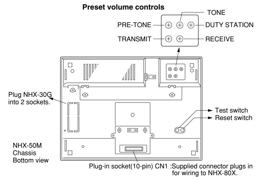
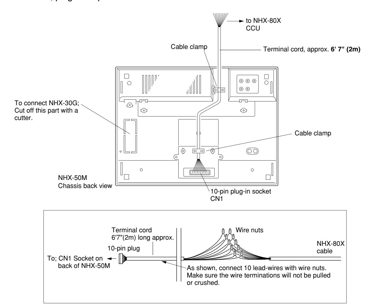
10 connector lead wires : connect to NHX-80X with 10 (5P) cable using wire nuts.
• NH-1SA/A NH-1SA NH-2SA/A NH-2SA NHR-3TS
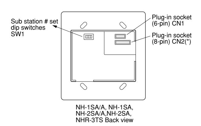
Plug in the supplied connector for wiring to Sub Trunk line.
Plug in the supplied connector for wiring to bathroom pullcord, corridor lamp & zone light #.
(*)7-pin on NH-1SA, NH-2SA and NHR-3TS
1 ~ 6: Connect 3P cable to Subs Trunk line. Ten stations per trunk, connected to NHX-80X 11 - 16 (up to 81 - 86) terminals.
ZL: Zone light to a Zone No. terminal (Z1 ~ Z4)
• NHR-SP
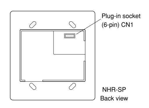
Plug in the supplied connector for wiring to NHX-80X.
CAUTION: When NHR-SP Duty Station is installed, remove the Shorting Connector (CN104) on NHX-80X CCU.
1. NHX-80X CCU to NHX-50M, NHX-30G & Duty station
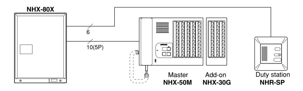
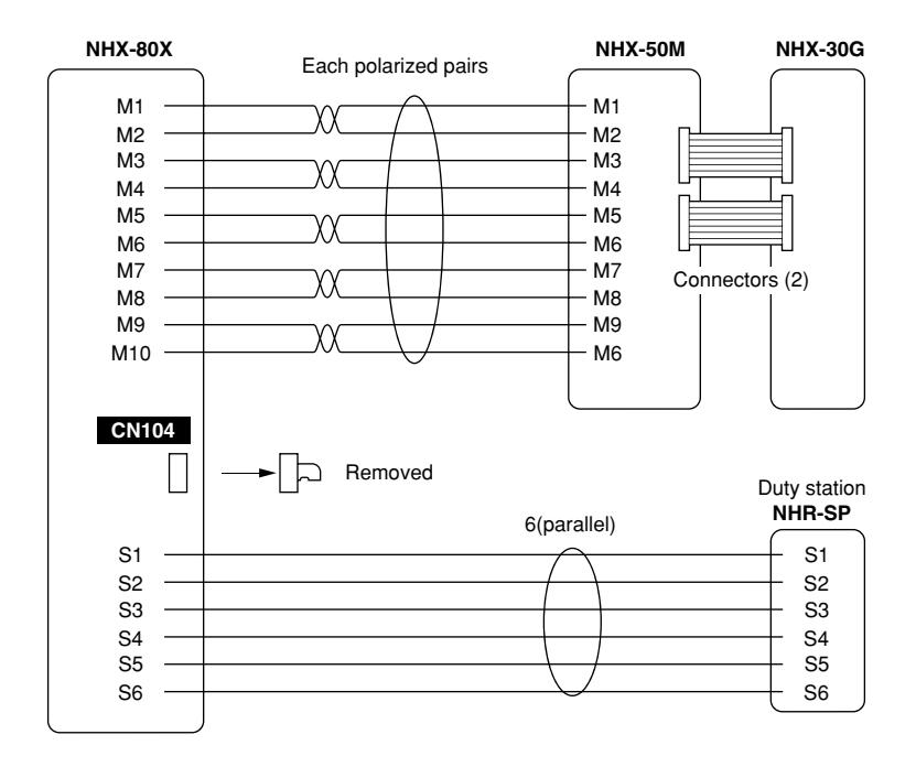
Wiring on NHX-80X CCU
* Use UL Listed cable for all wiring.
| To: NHX-50M | To: NHR-SP | |
|---|---|---|
| Cable | 5P | 6 parallel conductors |
| Distance |
65' w/22AWG
(20m w/0.65mmø) |
65' w/22AWG
(20m w/0.65mmø) |
* When Duty station (NHR-SP) is installed, remove the shorting connector from CN104 socket . Line-off trouble will be activated at the NHX-50M when wires to NHR-SP are broken.
* The Shorting connector is kept in the CCU, attached to internal wires. It is necessary only when wires to NHR-SP are broken. To silence the tone, plug in the shorting connector until NHR-SP is restored to normal operation.
2. Zone lights
NHX-80X Zone light NHR-3A-4 PS-24E or PS-2420 power supply. 1 2 3 4 5 5 5 9 PS-24E or PS-2420 power supply.
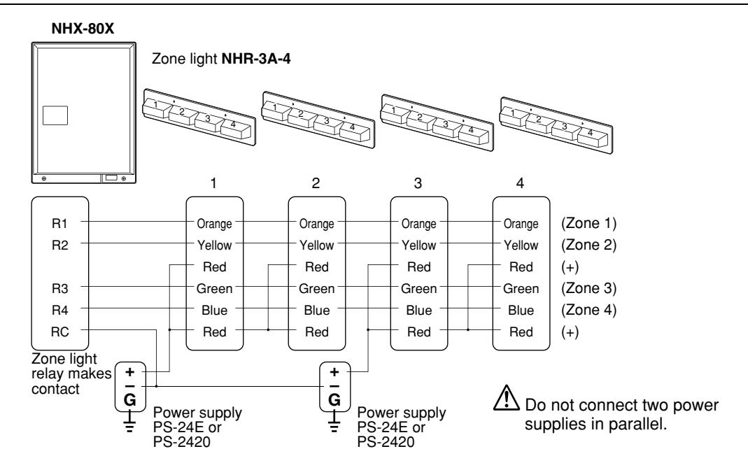
Wiring on NHX-80X CCU * Use UL Listed cable for all wiring.
| To: Zone light | |||
|---|---|---|---|
| Cable | 5 parallel conductors | ||
| Distance |
165' w/18AWG
(50m w/1.0mmø) |
||
* The NHX-80X zone light connection terminals (R1~R4, RC) are rated: DC 24V, 4A.
• Lamp; Rated DC 24V ~, 100mA (each lamp). Total 400mA per NHR-3A-4.
■ Schematic diagram of Zone light NHR-3A-4
* Take G terminal to earth ground on each
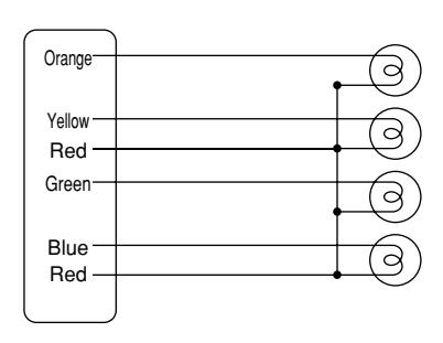
* Power supply for Zone light(s); Use a power supply rated 24V DC, 2A. A second PS-24E or PS-2420 power supply is required for Zone lights 3 & 4.
3. NHX-80X CCU to Sub stations
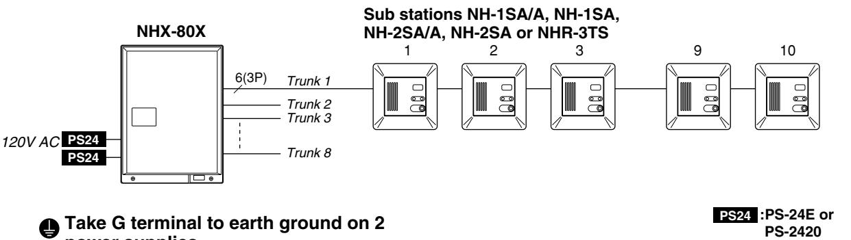
power supplies.
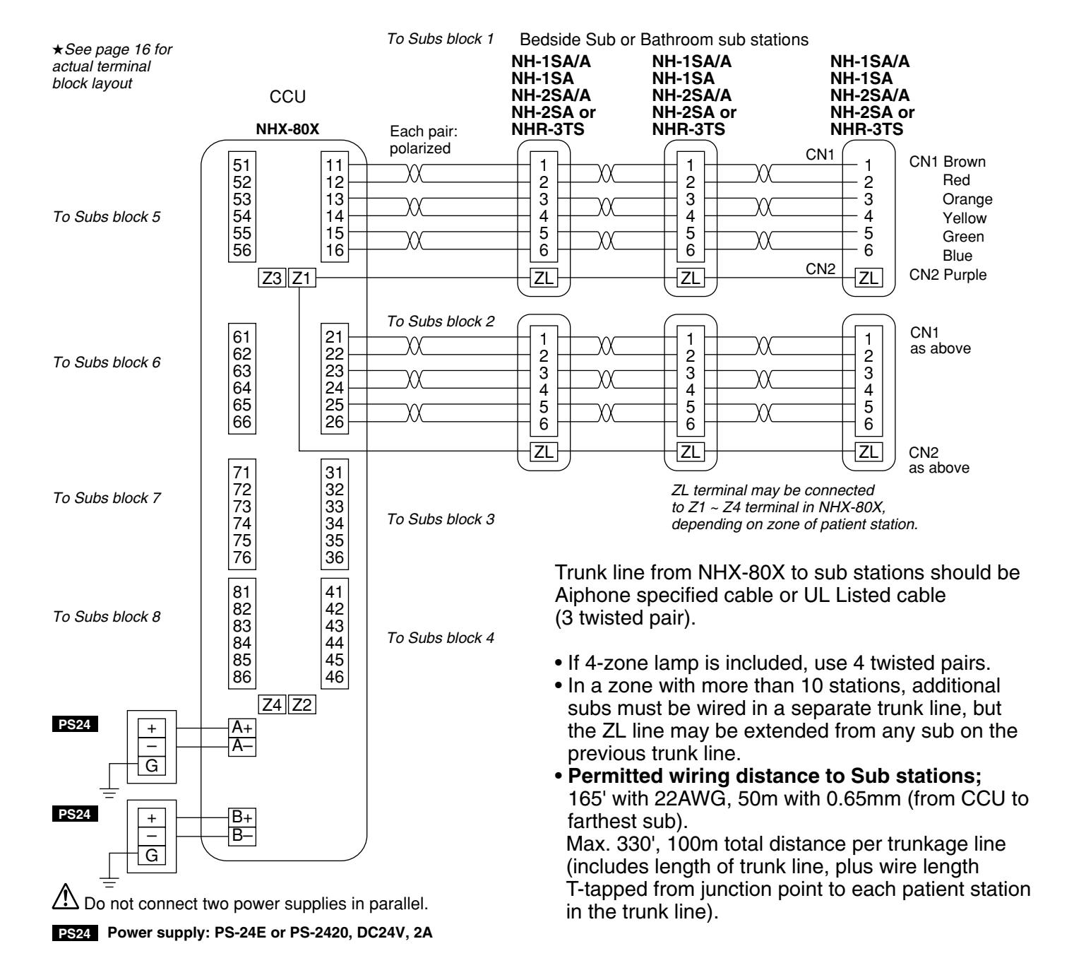
4. Bedside sub stations w/Corridor lamp & Bathroom Pullcord
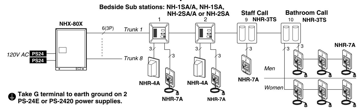
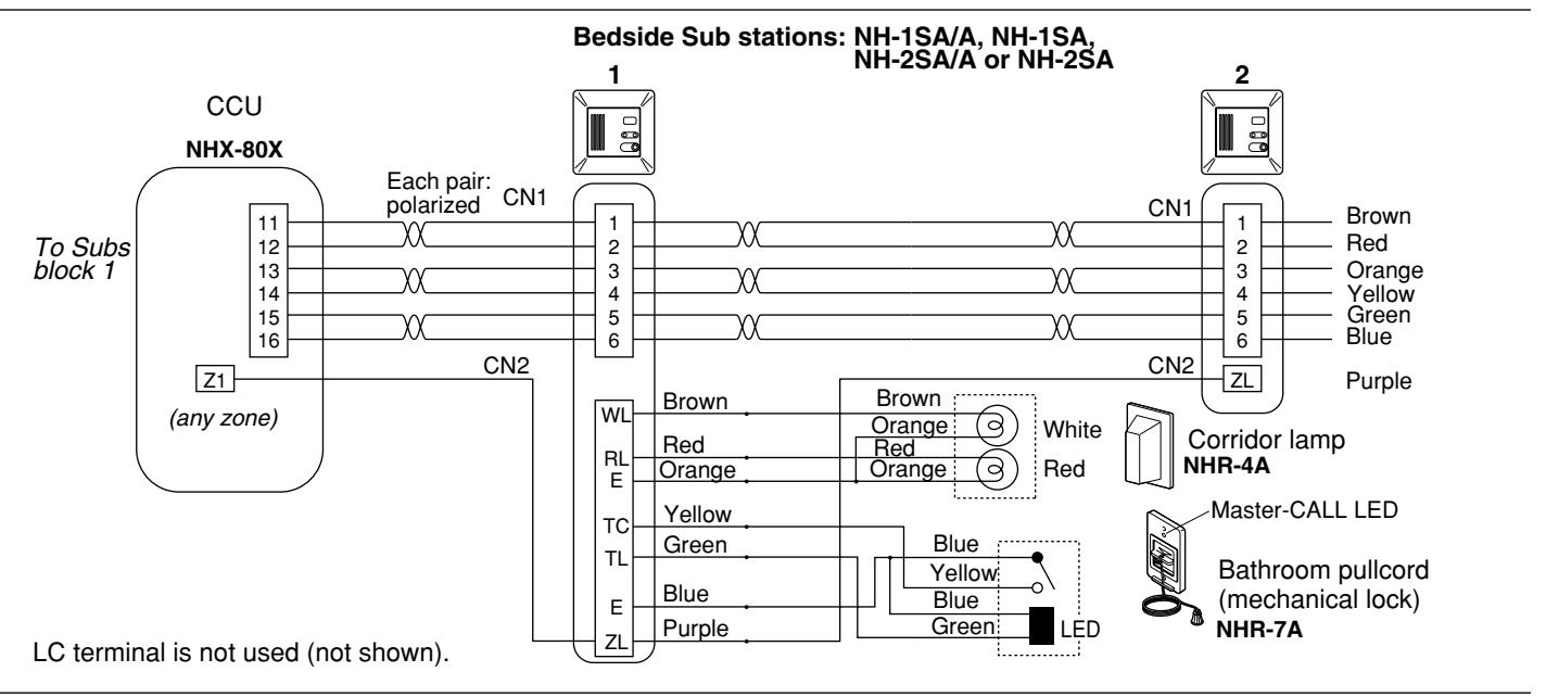
5. Bathroom call sub station: NHR-3TS

Multi-Station Patient Room Applications
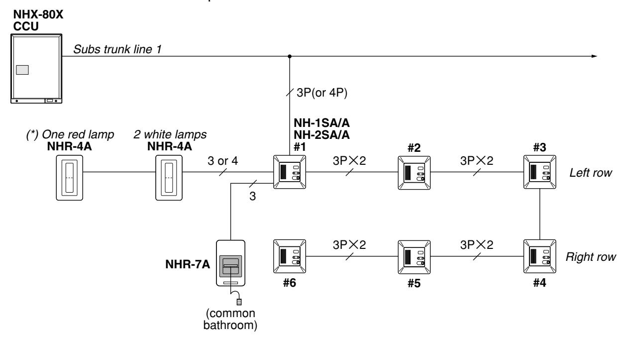
Multiple NH-1SA/A and NH-2SA/A bedside sub stations can also be installed within a patient room. Observe the following conditions:
- Max. 6 bedside sub stations may be connected per room for max. 12 calls (when NH-2SA/A stations are used).
- A corridor lamp inside (NHR-4A) must not be connected with more than 4 bedside sub stations.
- Due to the above, install two NHR-4A corridor lamps when more than 4 sub stations are in one room, i.e. two WHITE lamps used in one NHR-4A, and one RED bulb used in the other NHR-4A.
- NH-1SA/A and NH-2SA/A station numbers must be programmed in numerical order and connected to the same substrunk line.
- NHR-7A bathroom pullcord is optional.
1. Four bed application covered by four NH-1SA/A sub stations
with a common bathroom pullcord
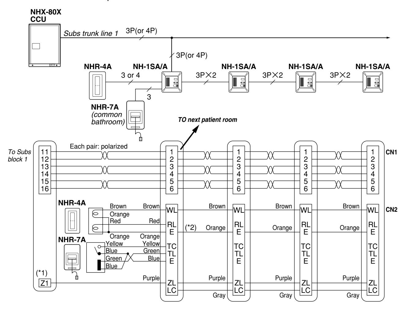
- (*1) Terminal Z1 for lighting Lamp 1 in NHR-3A-4.
- (*2) NHR-7A may be wired to any sub station convenient. Terminal RL is wired only on the sub station which NHR-7A is connected to.
The above example shows a patient room with four beds, in which a common bathroom pullcord is used. Multiple sub applications can be arranged in the following manner.
| Beds in Room | Subs combinations | Beds in Room | Subs combinations |
|---|---|---|---|
| 2 | One NH-2SA/A or two NH-1SA/A | 7 | Three NH-2SA/A & one NH-1SA/A |
| 3 | One each NH-2SA/A & NH-1SA/A | 8 | Four NH-2SA/A |
| 3 | or three NH-1SA/A | 9 | Four NH-2SA/A & one NH-1SA/A |
| 4 | Two NH-2SA/A or four NH-1SA/A | 10 | Five NH-2SA/A |
| 5 | Two NH-2SA/A & one NH-1SA/A | 11 | Five NH-2SA/A & one NH-1SA/A |
| 6 | Three NH-2SA/A | 12 | Six NH-2SA/A |
Note; Bedside sub station Models: NH-1SA and NH-2SA CANNOT be used in multiple bed patient rooms.
Multi-Station Patient Room Applications
2. Max. 12 bed application covered by six NH-2SA/A sub stations
with or without a common bathroom pullcord
(*) Requried only when NHR-7A bathroom pullcord is used.
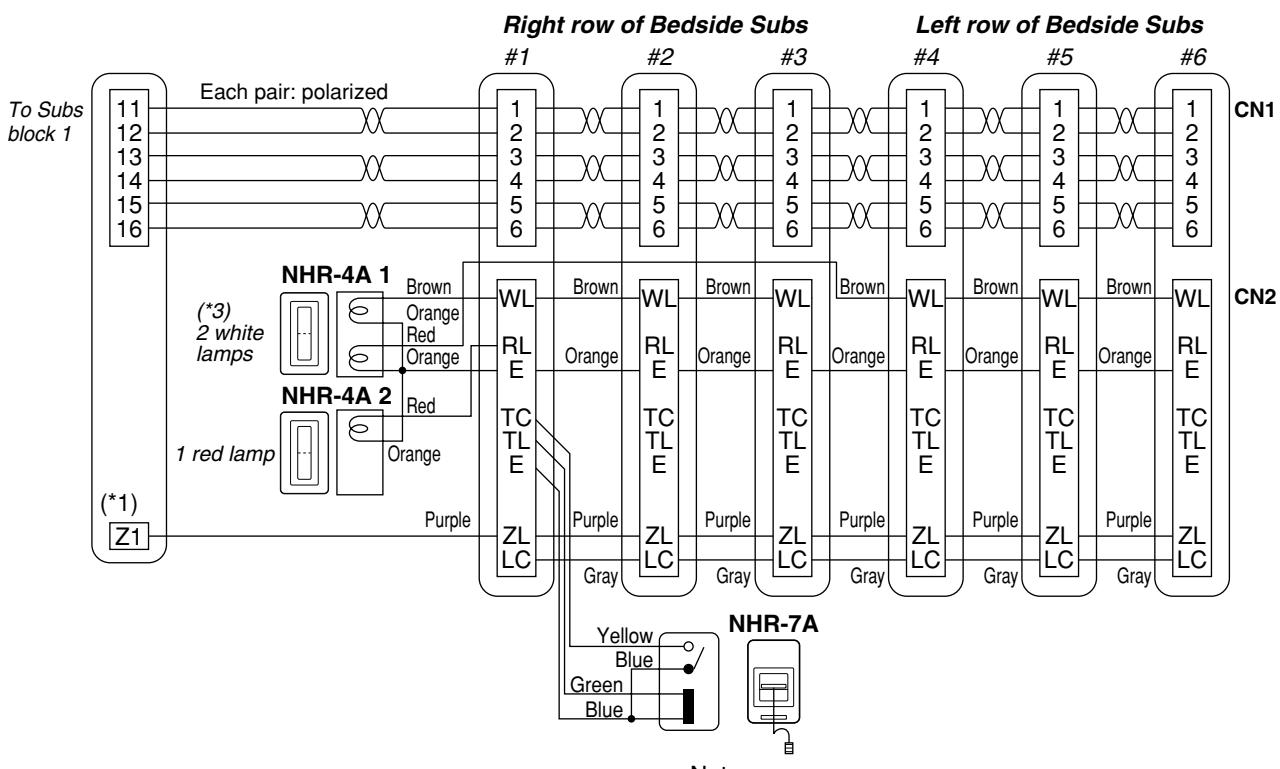
- (*1) Terminal Z1 for lighting Lamp 1 in NHR-3A-4.
- (*2) NHR-7A may be wired to any sub station convenient. Terminal RL is wired only on the sub station which NHR-7A is connected to.
- (*3) Remove the red cap on a lamp inside.
- Notes:
- In the above example, NHR-4A 2 is required only when NHR-7A, bathroom pullcord is installed in single and common bathroom.
- 2. Bedside sub stations Models: NH-1SA and NH-2SA CANNOT be used in multiple bed patient rooms.
4 MOUNTING
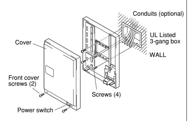
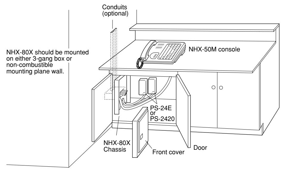
The NHX-80X should be mounted on either 3-gang box or on inside UL Listed electrical enclosure. To open the front cover ;
- 1. On the NHX-80X, pull at bottom of the cover and lift cover off the chassis.
- 2. Unplug CN-1~CN-5 connectors to disconnect from chassis.
■ Mounting NHX-50M on 3-gang box Chassis mounts on "flush" box with no extension or spacer. (screwless wire terminations)
■ Mounting NHX-80X inside Electrical Enclosure The size of the electrical enclosure should be more than 23-5/8" H×19-11/16" W×4" D. 600H×500W×100D (mm) and with secured door.
-
1. A suitable, non-combustible mounting surface adequately sized must be attached inside the enclosure. NHX-80X dimensions:
- 18-1/8" H×13-3/8" W×3-7/8" D. 460H×340W×98D (mm).
- 2. Cut off openings for cable inlet.
- 3. Secure chassis with 4 wood screws: 4.1mm×16mm.
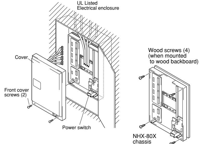
■ NHX-80X mounting example :
Underneath counter
4. MOUNTING
Mounting NHX-50M master station
As shown, NHX-50M can be wired to NHX-80X CCU, using terminal cord supplied. At NHX-50M end, plug in 10-pin connector.
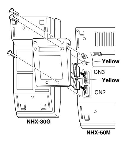
Assembling two Consoles: NHX-50M & NHX-30G
On the bottom of the NHX-50M, cut off the socket part and plug 2 connectors from the NHX-30G into the socket. Mount the cover at 3 points, which connects NHX-50M & NHX-30G units together.
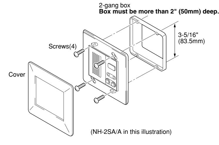
2-gang semi-flush mounting (NH-1SA, NH-2SA, NHR-SP, NHR-3TS)
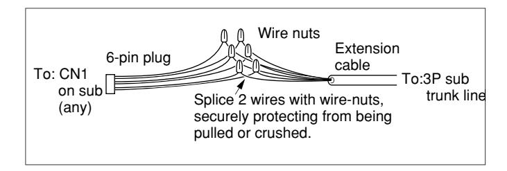
The sub station flush-mounts in 2-gang box (UL Listed). Cover clicks to attach. As shown terminate connector wires to the Trunk line with wire nuts, and plug into the socket.
Sub station back case dimensions (in recess);
| H | W | D | H | W | D | |
|---|---|---|---|---|---|---|
|
NH-1SA/A,
NH-2SA/A |
68.5 | 86.5 | 35 | 2-11/16" 3-7/16" 1-3/8" | ||
| NHR-3TS | 68.5 | 86.5 | 45 | 2-11/16" 3-7/16" 1-3/4" |
Sub trunk line cabling
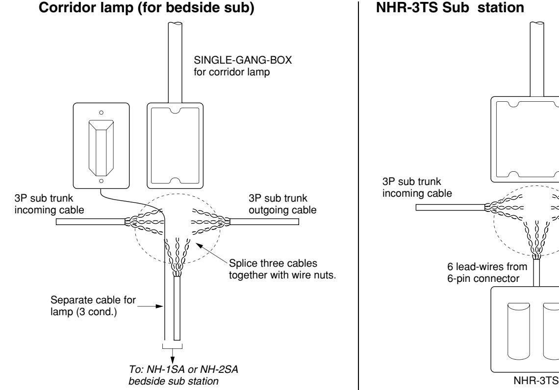
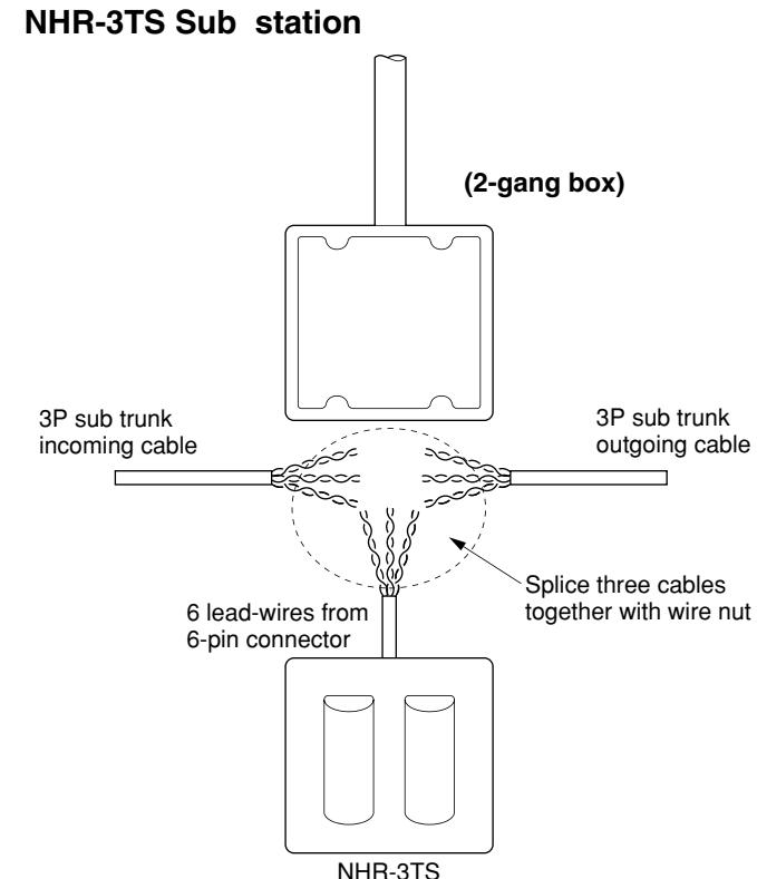
It is recommended to use a junction box to divide 3P trunk line to each Sub station. Splice three cables together, i.e. Trunk line in & out cables and the cable going to the Sub at the Singlegang box of Corridor lamp or 2-gang box for NHR-3TS.
- CAUTION: THE TOTAL SYSTEM CHASSIS RISK CURRENT SHOULD NOT EXCEED 500µA.
- ATTENTION: LE COURANT DE RISQUE TOTAL ADMISSIBLE AU CHASSIS NE DOIT PAS DEPASSER 500µA.
NHR-4A
- 1. Remove the lamp cover, pressing on both sides.
- 2. Terminate 3 wires from NH-1SA/A or NH-2SA/A bedside sub.
- 3. Mount NHR-4A on 1-gang box with 2 screws supplied.
- 4. Reattach the lamp cover.
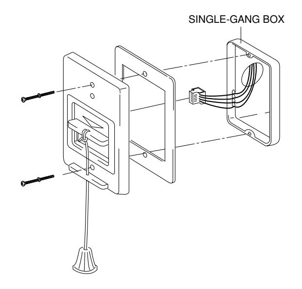
NHR-7A
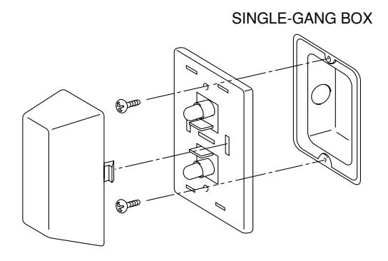
- 1. Terminate 3 wires from NH-1SA/A or NH-2SA/A. bedside sub or NHR-3TS common area call station.
- 2. Mount NHR-7A on 1-gang box.
- 3. For bathroom call, tie up pullcord supplied.
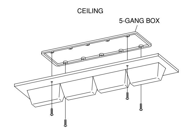
NHR-3A-4
- 1. Put number labels (1 ~ 4) on lamp covers.
- 2. Terminate 5 wires from NHX-80X as follows;
R1 to Orange (Zone 1)
R2 to Yellow (Zone 2)
R3 to Green (Zone 3)
R4 to Blue (Zone 4) and
RC to Red (PS-24E terminal)
3. Mount NHR-3A-4 to 5-gang box with 4 screws supplied.
At NHX-50M 5 OPERATIONS on NHX-50M
• Receiving a Routine Call (Bedside)
At NHX-50M At site
When a Bedside sub station presses CALL button;
- 1. Single chime tone rings on NHX-50M every 6 seconds, and a call-in LED blinks slowly every 2 seconds.
- 2. Press TONE-OFF button to silence tone. The LED above is lit.
- 3. Go to the Sub station. Press CANCEL button to reset.
For communication;
- 1. Simply lift handset and communicate (voiceactuated). Or press TALK button and communicate.
- 2. At conclusion, replace handset, or press OFF button.
A corresponding zone lamp is steadily lit.
At corridor lamp;
At Zone light;
White lamp is steadily lit.
At Sub station;
While NHX-50M is ringing, red CALL LED is lit, and stays on even after TONE-OFF is pressed.
OR When NHX-50M replies, green 'TALK' LED is lit. 'TALK' LED goes out when communication is finished.
• Receiving a Bathroom Pullcord Call (or call from NHR-3TS sub)
At NHX-50M At site
When a cord is pulled at Bathroom;
- 1. Single chime tone rings on NHX-50M every 1.8 seconds, together with LED double blinking.
- 2. Press TONE-OFF button to mute. The LED above is lit for attendance.
- 3. At Sub station, attendant unlocks CALL switch to reset the call.
At Zone light;
Light will indicate which zone has a call placed.
At corridor lamp; Red light blinks.
At Sub station;
Red CALL LED is lit.
* Communication is not available from Bathroom.
• Receiving a Cord-Out Trouble Call
At NHX-50M At site
When a plug has been pulled out of jack;
- 1. Single chime tone rings on NHX-50M every 0.5 seconds, and a call-in LED blinks fast.
- 2. Press TONE-OFF button to silence tone. The attendance LED is lit above.
- 3. At the Sub station, attendant may plug the pullcord back into jack to reset the call.
Light will indicate which zone has a call placed.
At Corridor lamp; White light blinks.
At Zone light;
At Sub station;
Red CALL LED is lit. When the pullcord is plugged in, all lights are reset.
* To communicate, either lift handset or press TALK button to establish channel.
At NHX-50M
• Placing Call
At NHX-50M At site
To call a Bedside Sub station;
- 1. Press a Sub selector button. The red LED is steadily lit.
- 2. Lift handset and communicate, voice actuated. OR Press TALK button to talk, and release to listen.
- 3. At conclusion, replace handset, or press OFF button.
• Volume Adjustments
Speaker receive voice volume & call tone signal are adjustable as needed on the left side of NHX-50M. RECEIVE: 3 positions. TONE: 3 positions
At Zone light; Not lit. At Corridor lamp; Not lit. At Sub station; Pre-tone sounds, and green TALK LED is lit.Communicate handsfree.
• When multiple calls are received
Up to 5 calls from subs can be displayed simultaneously, and additional calls are placed on hold (Zone light only will be on). When a call is answered and reset, the next call on hold will light on the NHX-50M, until all calls are answered.
• Other operations
- 1. Call-in during communication will activate both call tone & LED.
- 2. While call tone is muted, call-ins will be annunciated by tone & LED in the order of urgency first, then in the order they were received.
At Duty Station
When a bedside or NHR-3TS sub station has placed any type of call, the duty station indicates a Routine, Urgent Bathroom call or Cord-out Trouble Call.
- 1. Call tone sounds, and CALL LED blinks.
- 2. Press TONE-OFF button to silence tone. NHX-50M keeps on ringing.
At NHR-3TS Sub station
• Urgent Bathroom Call Bathroom call sub station(NHR-3TS) is a 2-light corridor lamp in the hallway and the NHX-50M acknowledges a call;
- 1. When a pullcord has activated an urgent call to the NHX-50M, the NHR-3TS lamp blinks red.
- 2. Communication is not available. Wait for the attendant to come to the location.
• Urgent Staff Call
- 1. Press or pull an urgent call switch connected to NHR-3TS.
- 2. NHR-3TS lamp starts blinking white.(Red lamp cover is removed.)
- 3. Wait for the attendant to come to the location.
Call tone & light annunciation
(*) Sound & LED time is approximate.
| Type of calling | Call tone | Light | |
|---|---|---|---|
| At NHX-50M Master station | |||
| • Receiving |
Routine call
Bathroom call (urgent) Cord-out trouble call |
Single chime, every 6 sec.
Single chime, every 2 sec. Single chime, every 0.5 sec. |
Blinking, every 2 sec.
Double blinking, every 1.8 sec. Blinking fast, every 0.4 sec. |
| • Line-off trouble |
Bedside sub from Trunk
Duty station from NHX-80X |
Slow buzzer, intermittent
Faster buzzer, intermittent |
Lit 0.2 sec., every 2 sec.
No light |
| • While talking | Call tone (as above) | Call-in LED steadily lit | |
| At NH-1SA/A, NH-1SA, NH-2SA/A or NH-2SA Bedside Sub station | |||
| • Placing | Routine call | – | CALL steadily lit |
| Bathroom call (urgent) | – |
Not lit
CALL lit on Pullcord switch |
|
| Cord-out trouble call | – | CALL steadily lit. | |
| • While talking | – | CALL is off, and TALK is on. | |
| • When master calls in | Pre-tone | TALK is on | |
| At NHR-4A Room Corridor lamp (white/red) | |||
| • When Sub placed a call Routine call | – | White steadily lit | |
|
Bathroom call (urgent)
Cord-out trouble call |
–
– |
Red blinking
White blinking |
|
| While talking | – | Not lit | |
|
At NHR-3A-4 Zone light
• When Sub placed |
Routine call | – | 1 ~ 4 lamp turns on for any call from |
| Urgent call | – | Bedside sub or NHR-3TS. | |
| Cord-out trouble call | – | ||
| At NHR-3TS sub station (w/corridor lamp) in Common area or Hallway | |||
| Placing | Bathroom call (urgent) | – | Red blinking on NHR-3TS |
| Staff call (urgent) | – | White blinking on NHR-3TS | |
| At NHR-SP Duty station | |||
| • When Master received Routine call | Single chime, every 6 sec. | CALL blinking, every 2 sec. | |
| Urgent call | Single chime, every 2 sec. | CALL double blinking, every 1.8 sec. | |
| Cord-out trouble call | Single chime, every 0.5 sec. | CALL blinking fast,every 0.4 sec. | |
| While Master talking | – | Not lit | |
|
Calling from NHX-50M
except TALK LED lit green on the sub station. |
When NHX-50M has called a bedside Sub station, no light turns on on the corridor lamp, zone light and sub station | ||
6 TECHNICAL PRECAUTIONS
Temperatures
NHX-80X and NHX-50M are rated to operate at temperatures 10˚C~49˚C(50˚F~120˚F).
Duty Station Operation
At NHR-SP, sub station call-in is annunciated by tone & LED, which are the same as on NHX-50M.
- The TONE-OFF button silences tone, but CALL LED remains lit. When the NHX-50M begins communication, both tone and LED are deactivated.
- 90 seconds after the call tone is muted, it will ring again. Press TONE-OFF button, and it will no longer ring (tone will resume when another sub calls).
Call Holding
Every Routine call is held electronically at bedside sub station, and will be automatically connected when handset is lifted or TALK button is pressed at the NHX-50M. To reset the call, press CANCEL button on the Sub station. When a Bathroom call & Cord-out trouble call is activated, the LED will remain on even after the NHX-50M has answered. The call must be reset at the calling site.
RESET switch
Do not use RESET switch except for initializing or testing the NHX-80X. If RESET is pressed while a call is being placed or a Bathroom call or Cord-out trouble call has been placed, it will suspend the call.
* Do not press RESET switch except when installing, changing subs, or when system malfunctions.
Adjusting Preset Volumes
On the bottom of the NHX-50M, adjust volume controls to desired level.
- * TRANSMIT: Adjusts the NHX-50M's voice heard at bedside sub.
- * RECEIVE: Adjusts the speaker volume on NHX-50M. Adjustable 3-position control on the left panel.
- PRE-TONE: Adjusts pre-tone to the desired level heard at bedside sub.
- TONE: Adjusts initial call tone level. 3-position switch varies volume from preset level (user-adjustable).
- DUTY STATION: Adjusts call tone level heard at Duty Station
When System Malfunctions;
Call tone sounds on the NHX-50M without being called. Call-in LED is lit, but no call tone.
In such occasions, check the status of system, and turn power switch off and on again at the NHX-80X. If the system does not return to normal operation, turn OFF power switch and contact your installing dealer or Aiphone.
Call priority:
- 1. Cord-out trouble call
- 2. Bathroom call, or NHR-3TS common area bathroom call or staff call (urgent call),
- 3. Routine call
In Standby mode;
Priority is put in the order of Cord-out trouble call, Bathroom call and Routine call.
Cord-out trouble call is put in first priority, and overrides any other calls on the system.
During communication;
The NHX-50M master station sounds an incoming call tone while talking to another station, the same as in standby mode. A new call doesn't override an existing conversation. Reply after concluding current call.
Up to 5 sub call-ins can be displayed on the selector switch bank. All the calls placed are held in a queue, and will resume light and tone at NHX-50M after each previous call is concluded.
Momentarily hang up handset, and the next call tone is audible. The sixth call will not illuminate on NHX-50M nor on Corridor lamp (Only zone light will be lit).
The NHX-50M is capable of having as many calls held as there are sub stations. To reply to next call, hang up and lift handset or press TALK button to establish channel.
- If calls are of the same level; in the order of time of call,
- If calls are of different levels; in the order of urgency.
Operational Modes in Multi-Station Patient Room application
When single or multiple calls have been placed from the same patient room, corridor lamp will be activated as follows;
| Type of calls placed | Corridor lamp | |||
|---|---|---|---|---|
| Sub1 |
Sub2
Sub2 |
Sub3 | Red | White |
| Routine |
–
– |
– | – | Steady |
| – |
Bathroom
Bathroom |
– | Blinking | – |
| – |
–
– |
Cord-out | – | Blinking |
| Routine |
Bathroom
Bathroom |
– | Blinking | Steady |
| Routine |
–
– |
Cord-out | – | Blinking |
| – |
Bathroom
Bathroom |
Cord-out | Blinking | Blinking |
| Routine |
Bathroom
Bathroom |
Cord-out | Blinking | Blinking |
Warning tone
- (1) If a call has been left unanswered for 90 seconds, the call tone volume will go up to HIGH level regardless of the set position.
- (2) If handset is left off the hook at NHX-50M for 90 seconds during communication, a warning tone(steady) will be heard. Replace handset, and the tone will stop.
Line-off Trouble: Connector unplugged status on Bedside or Bathroom call sub stations & Duty station
When a buzzer warning tone (*) has been activated at the NHX-50M, the wire connector is disconnected from the back of the Sub station or Duty Station. The warning tone cannot be silenced by TONE-OFF button. To mute the slow buzzer (with a blinking call-in LED on the corresponding Sub), either lift handset or press TALK button. To mute faster buzzer with no LED lit, remount the shorting connector (**) on CN104 at the NHX-80X. The Duty Station will no longer be acknowledged. To restore, call the installing dealer or Aiphone.
- (*) Line-off Trouble detects disconnected status of 3, 4, 5 & 6 wires only on sub station.
- (**) Shorting connector is attached to the internal wires inside the NHX-80X.
Other Operations
- (1) On a corridor lamp, the white lamp steadily lit (during routine call) may vary if another bathroom call or cord-out trouble call has been placed in the same trunk.
- (2) A pullcord call in a bathroom illuminates the master call indicator lamp on the panel.
If another call has been placed from a bathroom nearby, the lamp will look dimmer on both units.
Fuse replacements
If either fuse blows, there is a problem with the system's power or wiring. Turn power switch on NHX-80X off, and call the installing dealer immediately. The cause of the problem must be found and resolved before new fuses are installed, restoring the system to normal operation.
Two UL Listed replacement fuses (250V AC, 3A) are included in the NHX-80X.
7 SPECIFICATIONS (NHX-80X)
• Power source: NHX-80X: 24V DC.
• Current consumption: Max. 4A.
• Power supply: Install two power supplies PS-24E or PS-2420 (Rated input 120V AC, 50/60Hz.
Rated output: 24V DC, 2A) to the NHX-80X.
All other accessories are powered by NHX-80X Central Control Unit except for
Zone light Model: NHR-3A-4.
• Station capacity: 50 sub stations (NHX-50M), plus 30 sub stations (NHX-30G).
Add NHR-30K when NHX-30G is included.
• Talk channel: Single and private. • Call-in priority: 1. Cord-out trouble call.
2. Bathroom call, room or common area, or NHR-3TS staff call (urgent call).
3. Routine call.
• Wiring: Use UL Listed twisted pair only copper conductor cable for all wiring.
6 (3P) looped, CCU to a trunk line of 10 subs.
10 (5P), CCU to NHX-50M.
• Wiring distance:
| 22AWG | 0.65mmø | |
|---|---|---|
|
CCU to farthest sub
Each sub trunk line must not exceed; |
165'
165' 330' 330' |
50m
100m |
| CCU to NHX-50M |
65'
65' |
20m |
| CCU to Duty station |
65'
65' |
20m |
| 18AWG | 1.0mmø | |
|---|---|---|
| CCU to Zone light |
165'
165' |
50m |
| CCU to Power supply |
16'
16' |
5m |
WARRANTY
Aiphone warrants its products to be free from defects of material and workmanship under normal use and service for a period of one year after delivery to the ultimate user and will repair free of charge or replace at no charge, should it become defective upon which examination shall disclose to be defective and under warranty. Aiphone reserves unto itself the sole right to make the final decision whether there is a defect in materials and/or workmanship; and whether or not the product is within the warranty.
This warranty shall not apply to any Aiphone product which has been subject to misuse, neglect, accident, or to use in violation of instructions furnished, nor extended to units which have been repaired or altered outside of the factory. This warranty does not cover batteries or damage caused by batteries used in connection with the product.
This warranty covers bench repairs only, and any repairs must be made at the shop or place designated in writing by Aiphone.
Aiphone will not be responsible for any costs incurred involving on site service calls.