Aiphone Master Sentry LEF-3C 5C 10C Instructions
Open the original PDF document
View PDF

MASTER SENTRY SEMI-FLUSH MOUNT LOUDSPEAKER SYSTEM
Models;
(3-call master)
(5-call master)
(10-call master)
INSTRUCTIONS
The LEF-C System is a semi-flush mount loudspeaker communication system, which can accomodate a communication network of up to 11 stations. By adding the PanTilt video system, the Master Sentry is the ideal communication system for residential and commercial applications. These instructions primarily explain the LEF-C audio system, with some references to integration with the video system. For more detailed information on the other components used with the system, see the instructions for those products.

NAMES AND FUNCTIONS
Master Stations LEF-5C
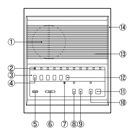
LEF-10C
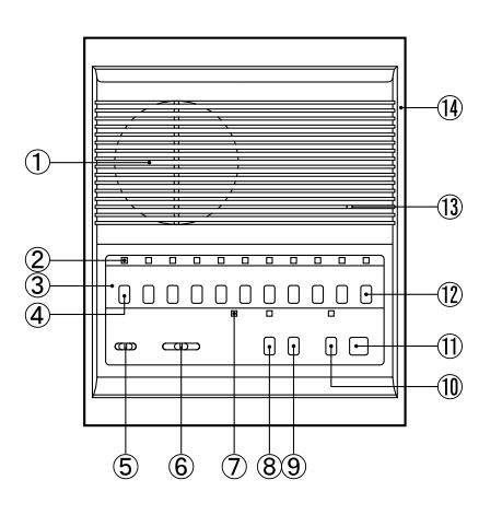
- ① Speaker
- ② Sub call-in annunciator LED (also illuminates on master to indicate the station is being selected)
- 3 Directory card & button identification plate
- 4 Station selector button
- ⑤ Music volume control
- 6 Communication volume control
- Occupied LED
- 8 All-call button & mode indicator
- Door Release button (not included on LEF-3C)
- 10 Privacy button PRIV. & mode indicator CALL TALK
- 11) Talk button
- 12 OFF button OFF
- (13) Microphone
- (14) Chassis

NAMES AND FUNCTIONS (continued)
Master Station LEF-3C
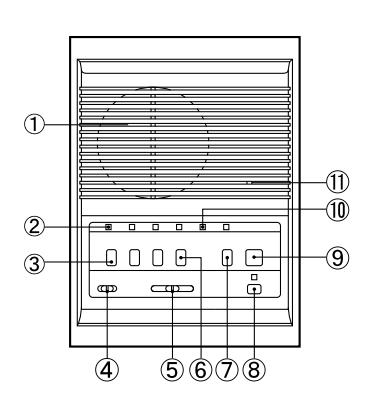
- 1) Speaker
- ② Call annunciator LED
- 3 Station selector button
- 4 Music volume control
- 5 Voice volume control
- 6 OFF button
- Privacy button & mode indicator
- 8 All-call button & mode indicator
- 9 TALK button
- ① Occupied LED
- 11 Microphone
Sub master station LEF-1C
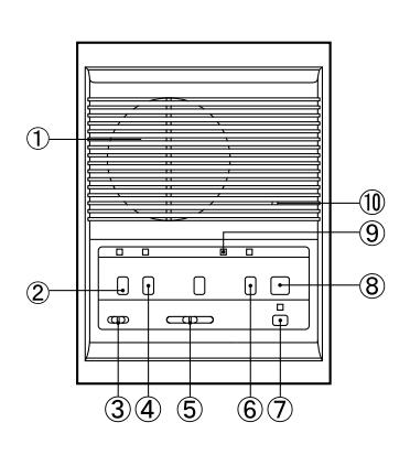
- ① Speaker
- 2 Privacy button & mode indicator
- 3 Music volume control
- 4 Door release button
- 6 Voice volume control
- Occupied LED
- 8 OFF button
- 9 All-call button & mode indicator
- 10 TALK button
- ① Microphone
Indoor sub stations LE-B. LE-BN
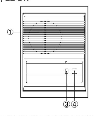
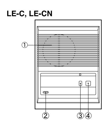
- 1 Speaker/microphone
- ② Music volume control (LE-C, CN only)
- ③ Privacy button & mode indicator ( LE-BN, CN only )
- 4 CALL button
Weather-resistant sub stations
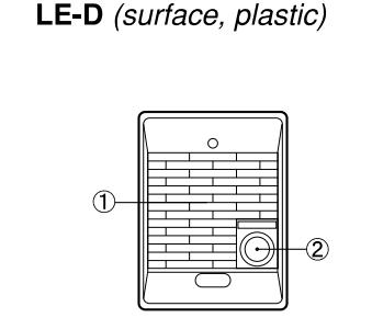
① Speaker/microphone
LE-DA (flush, stainless)
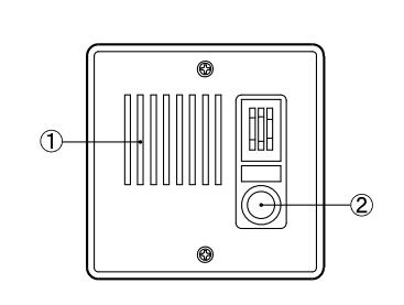
2 CALL button
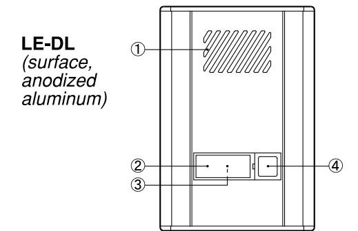
- ① Speaker/microphone
- 2 Directory card
- Illumination lamp (under directory)
- 4 CALL button

- 1. A wide variety of system configurations. All-master, Single-master or Intermixed systems can be created.
- 2. 3-call, 5-call & 10-call masters intermixable.
- 3. All-call from any LEF-C master station (when system includes BG-10C).
- 4. Background music (BG-10C All call amp. is required).
- 5. PanTilt video can be incorporated.
- 6. LEF-1C sub master adds more versatility, having All-call and door answering capabilities.

SYSTEM COMPONENTS
Basic Audio Communication;
| * Master stations; Select a suited master station for to form basic audio communication Listed models are semi-flush models. | on network. | * Models Available; LEF-3C: 3-call LEF-5C: 5-call LEF-10C: 10-call LEF-1C: 1-call sub master |
|---|---|---|
| * Sub stations; For locations requiring only calling room stations. Privacy button and are optional. Listed models are semi-flush models. | d Music volume control | LE-B: Standard LE-BN: Privacy LE-C: Standard w/music volume control LE-CN: Privacy w/music volume control |
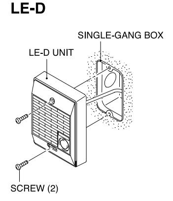
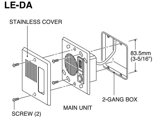
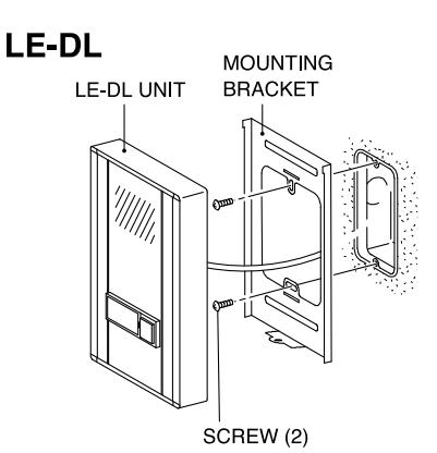
| * Door stations; To receive calls from guests, etc. door, rear door, or gate for entry a Weather resistant. | LE-D: Surface, plastic cover LE-DA: Flush, stainless steel cover LE-DL: Surface, anodized aluminum cover | |
| * Power supply; To supply power for audio comme either power supply to suit the system. |
PS-1225UL or PS-1225S:
DC 12V, 2.5A.
LEF units |
Optional functions; Video
| * For video entry security system; Max. 3 doors To incorporate video for entry security, use 1- or 3-camera adaptor to connect to PanTilt video systems. | MYW-P1L: 1-camera adaptor MYW-P3L: 3-camera adaptor MYH-CUB: Semi-flush video monitor MK-DAC: PanTilt video door station, surface, plastic cover MK-DBC: Semi-flush mount, plastic cover MK-DGC: Semi-flush mount, metal cover PS-1820UL or PS-1820S: Power supply for video |
|---|---|
| * All Call, Door Chime, and Music distribution; To have the All Call feature, and a chime from the door station(s), include the BG-10C (with related power supplies). |
BG-10C: All Call & Chime Adaptor
PS-1225UL or PS-1225S: Power supply for BG-10C |
(1) Mounting guidelines;
- Aiphone Corporation recommends that when installing any of its communication products, the wiring must be run at a distance of at least 2 feet (60cm) from any AC wiring, fluorescent lights, or dimmer switches.
- Aiphone Corporation is not responsible for improper installations of its products which result in interference generated by AC voltage, dimmer switches, fluorescent lighting fixtures, or other similar electrical devices. If noise is induced into the intercom system from one of these sources, it must be corrected at the source by the installing party.
LEF Audio Communication System Pre-Installation: Wiring
- ① Select the proper type of wire for the system being installed. Use the maximum number of conductors for the system. Consult the following wiring information to determine how many conductors will be required for your system, and what gauge is required.
- ② Shielded wire is recommended, but not required. It may help to minimize possible interference from outside sources. Use a multi-conductor cable with an overall shield, not twisted pairs. Run the cable in a "daisy-chained" configuration, in and out of each station in the system from beginning to end. Sub stations may be homerun to the nearest master station in the system. Door stations should be homerun to the main master station (where the BG-10C is wired into the system).
Note:
Some intercom stations require the same common wires, plus individual wires for each station on the same wire run. Assure that the cable has enough conductors for every station included. When running intercom cable, maintain a distance of at least 24" (60cm) from any AC wiring, fluorescent lighting, and dimmer switches. When crossing AC wires, do so at a 90° angle.
Avoid running intercom cable in the same stud space with electrical wiring, and install the intercom station on a different portion of the wall from electrical devices.
Installation
- ① Lay out your system in advance, determining which stations will be located in each room, and what their respective station number will be. Fill in this information on your wiring diagram.
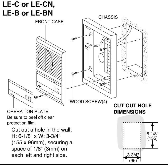
- 2 Cut the proper sized holes in the wall to semi-flush mount the intercom stations (C-version units only).
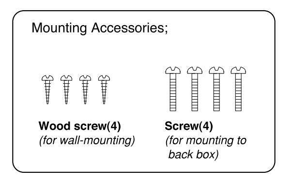
- ③ Separate the intercom from the back chassis by carefully removing the control panel cover and directory strip and loosening the screws. Lift up on the intercom portion before pulling it outward. Unplug the connectors, and store the intercom unit in the box until the wiring is completed.
- ④ Install the back chassis in the wall, and make wire connections as shown in the appropriate wiring diagram. Be sure to tighten screws securely onto the wires.
- ⑤ Reattach the intercom unit to the back chassis with the connectors, and place it on the back chassis from the top. Tighten the screws, and replace the directory strip and cover. Remove the plastic film over the control panel cover.
- ⑥ After all connections are made and intercom stations installed, test the operation of the system. Leave these instructions with the end-user for their reference. Fully train the end-user as to the functions and features of their intercom system. Advise the end-user on which rooms are assigned to each station number so they can fill in the directory card on each station.
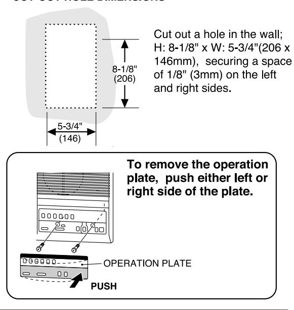
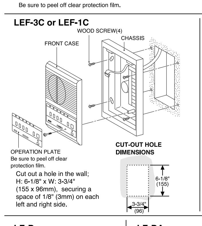
(2) Mounting instructions
LEF-5C or LEF-10C
CHASSIS WOOD SCREW(4) WALL FRONT CASE OPERATION PLATE
CUT-OUT HOLE DIMENSIONS
(3) Actual terminal locations;
LEF-5C LEF-10C
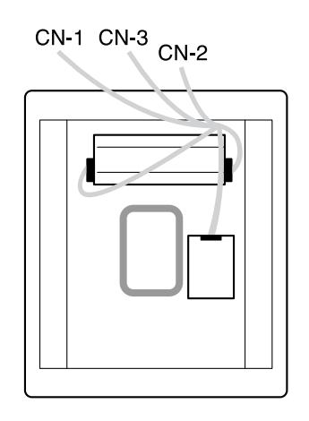
CN<sub>1</sub> 1 ~ 10 Station communication channels for
selective calling for common audio communication
CN 2 for power supply
Ε
for receiving a call and music С
R for occupied LED S for connection of external music speaker
(connected to S - E terminals)
for controlling occupied mode when called L
for door release (+12V DC when door
release button is pressed) for controlling all call
P1
P2, P3 for all call output
CN<sub>3</sub> K1 ~ K10 for selective door release, controlling video door
station, or control of remote devices (K# becomes negative when station button is depressed)
LEF-3C
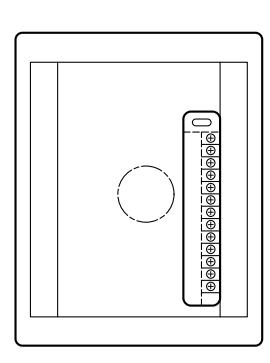
Station communication channels for
selective calling
for common audio communication Ε
for power supply
+ , C for receiving a call and music
R for occupied LED
S for connection of external music speaker
(connected to S - E terminals)
for controlling occupied mode when called
for door release (+12V DC when door
release button is pressed)
for controlling all call P1
P2, P3 for all call output
LEF-1C
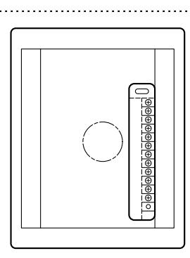
for receiving a call from master and music
Ε for common audio communication DA for door station communication
for power supply for occupied LED R
for controlling occupied mode when called
for door release (+12V DC when door release
button is pressed)
P1 for controlling all call
for all call output P2, P3
for video door station control
LE-C. LE-CN
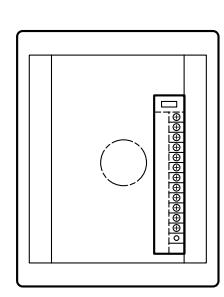
LE-B. LE-BN
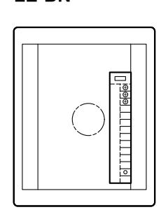
LE-D
LE-DA
Voice communication (to # on LEF-C) C Receiving music, All Call, and door
chime (w/BG-10C)
S-E External speaker output
E,R Common wires to LEF-C network
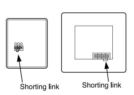
Voice communication (to # on LEF-C): Ε Common communication
Connect to - terminal
LE-DL
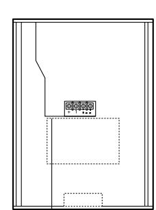
to supply power to lamp
voice communication (to # on
Ε Common communication

(1) LEF-3C audio communication system;
| No. | SYSTEM | MASTER | DOOR (audio) | ROOM SUB |
|---|---|---|---|---|
| 1 | All-Master system | 4 | ||
| 2 | with one door station | 3 | 1 | |
| 3 | Intermixed system | 2 | 1 | 1 |
| 4 | Single-Master system | 1 | 1 | 2 |
1 All-Master system
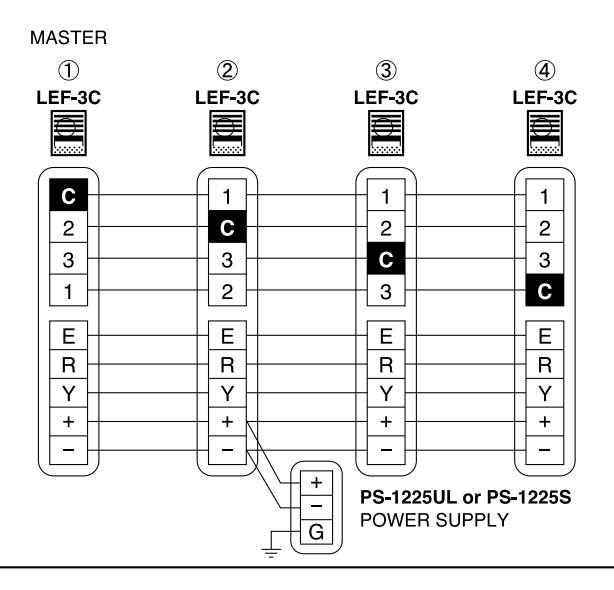
2 All-Master system w/one door station
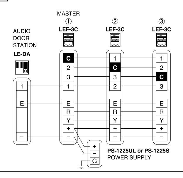
3 Intermixed System
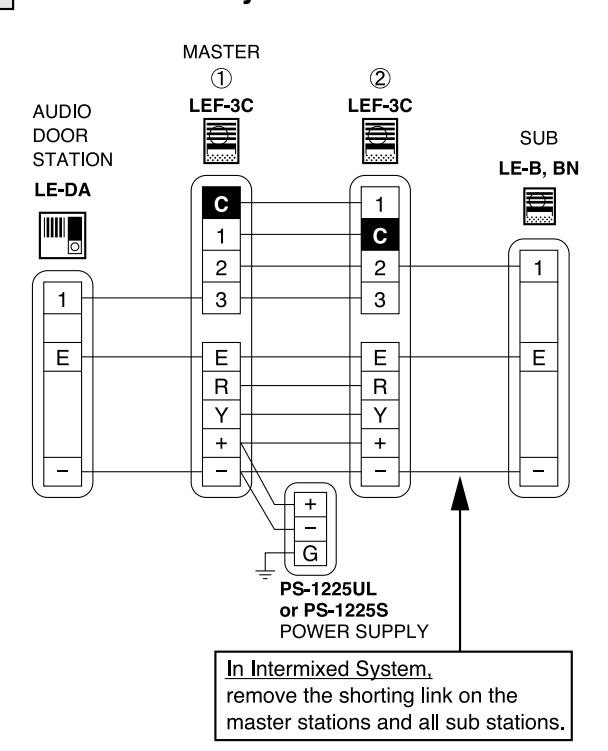
4 Single-Master system
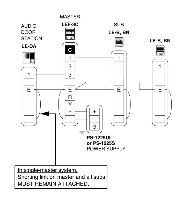

WIRING DIAGRAMS
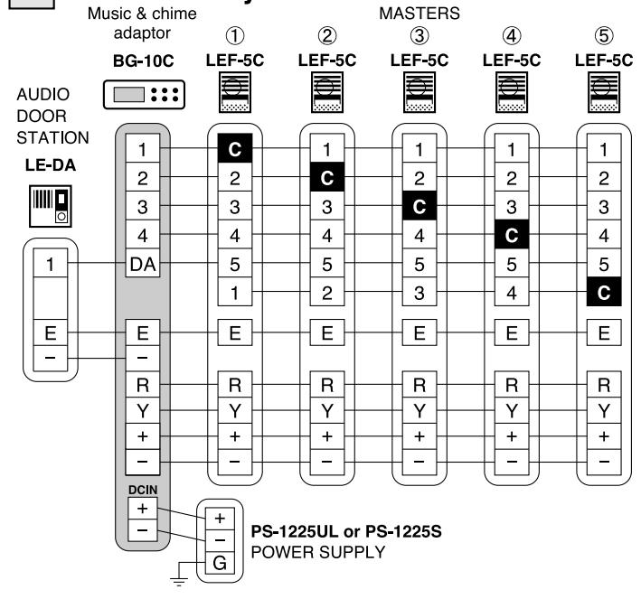
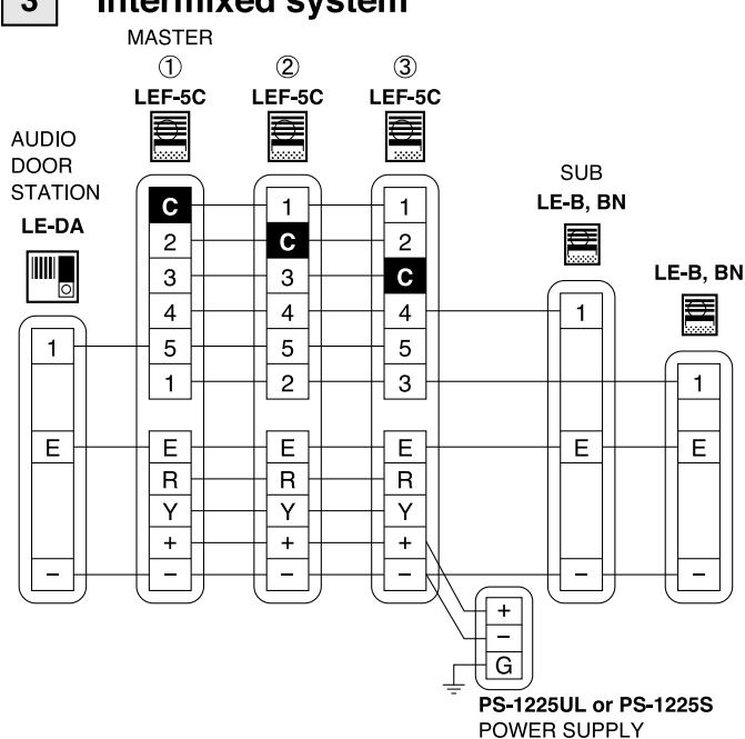
(2) LEF-5C audio communication system;
| No. | SYSTEM | MASTER | DOOR (audio) | ROOM SUB |
|---|---|---|---|---|
| 1 | A ll- Master system | 6 | ||
| 2 | All-Masters w/ door station | 5 | 1 | |
| 3 | Intermixed system | 3 | 1 | 2 |
| 4 | Single-Master system | 1 | 1 | 2 |
1 All-Master system
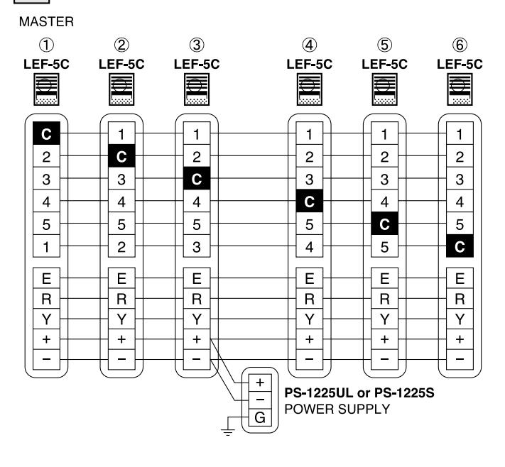
2 All-Master system w/one door station
3 Intermixed system
4 Single-Master system
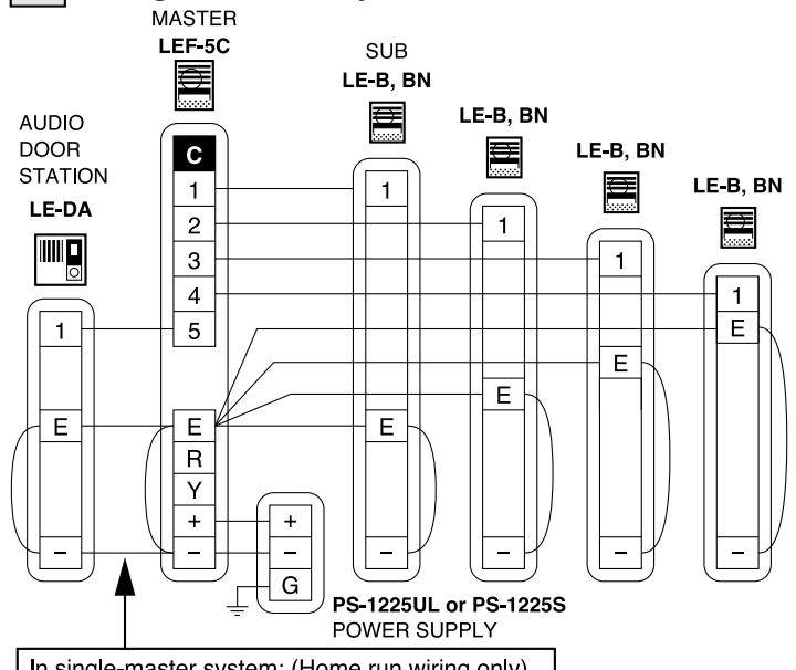
In single-master system: (Home run wiring only) Shorting link (between E & – terminals) on the master and all subs MUST REMAIN ATTACHED.
For daisy-chained wiring: Remove jumpers and run multi-conductor cable with 2 common plus 1 individual wire per station.

(3) LEF-10C audio communication system;
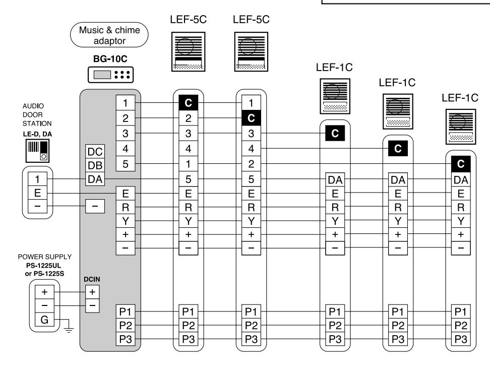
1 All-Master system with one door station All call & chime from door
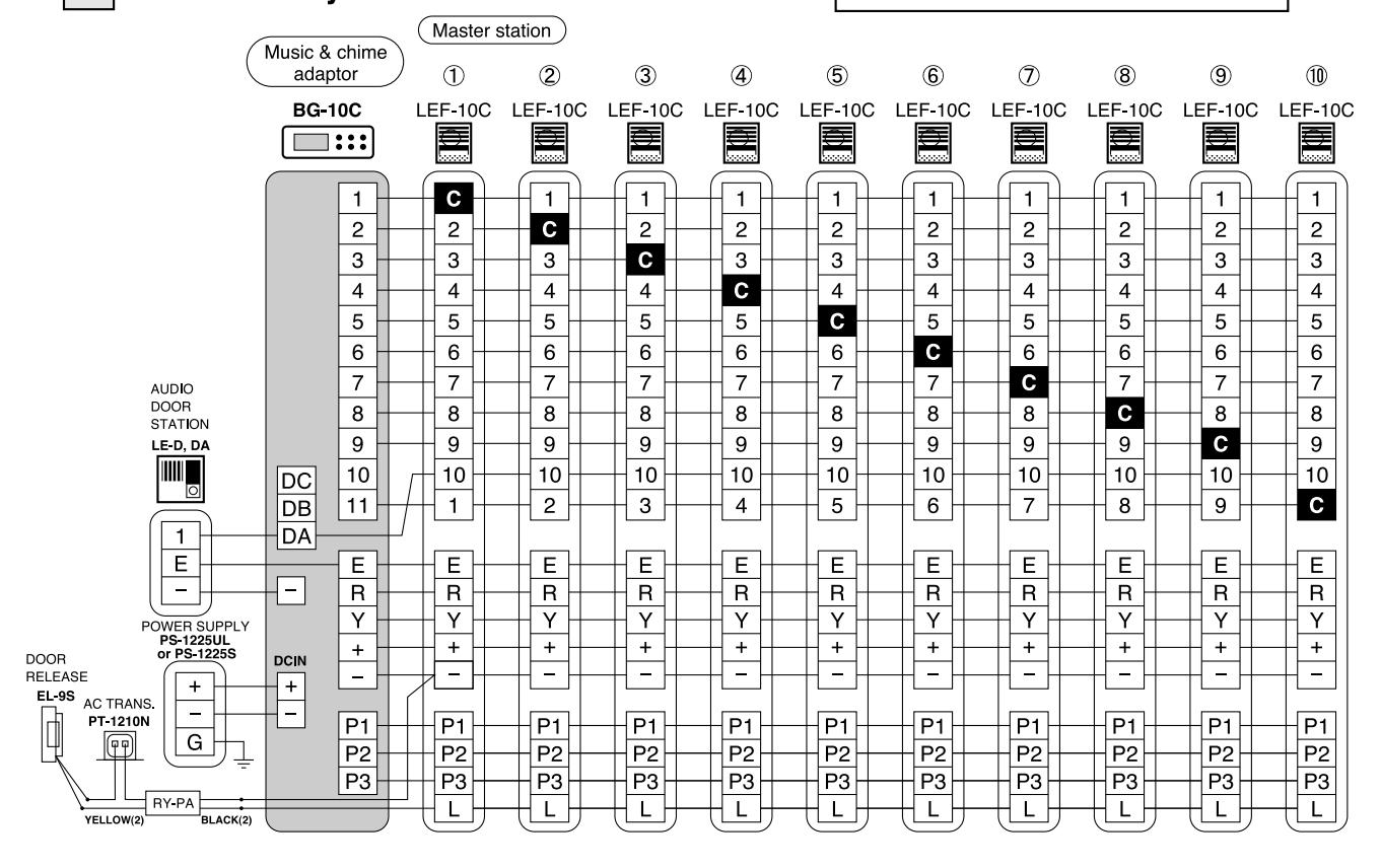
2 Dual Master w/ sub-masters
All call & chime from door

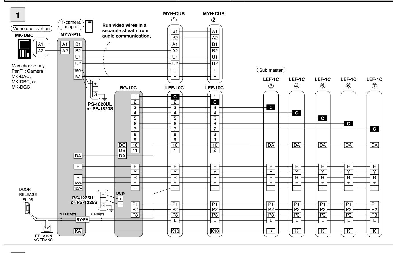
(4) 1 PanTilt video door station (MYW-P1L Adaptor)
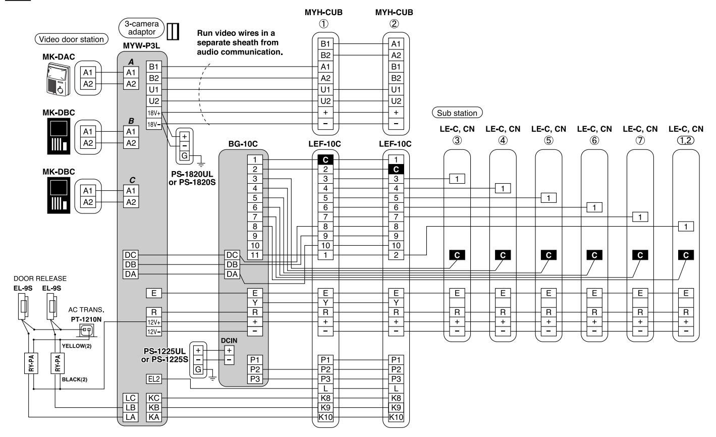
2 3 PanTilt video door stations (MYW-P3L Adaptor)
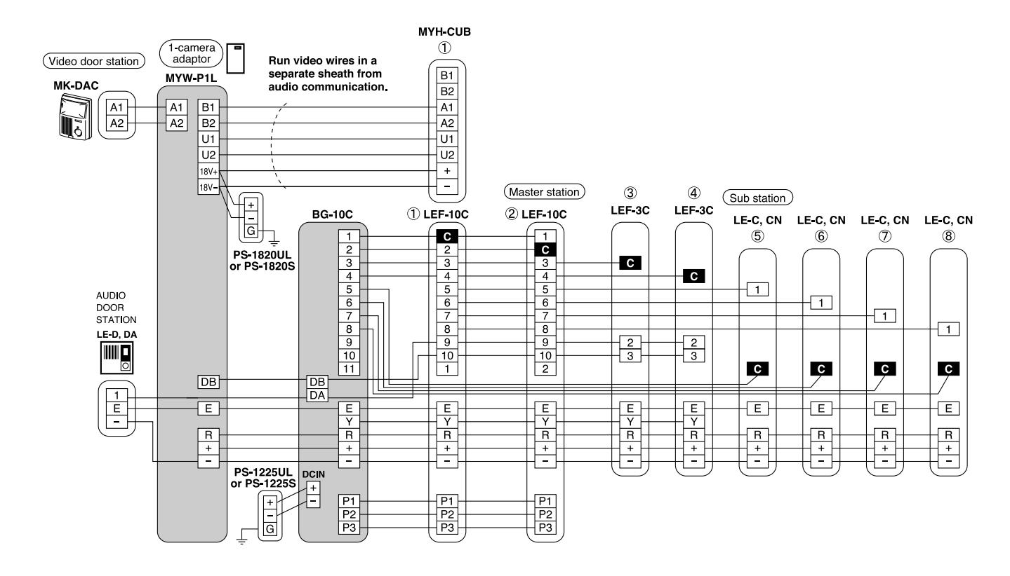
(5) Intermixed System - Audio and PanTilt Video
1
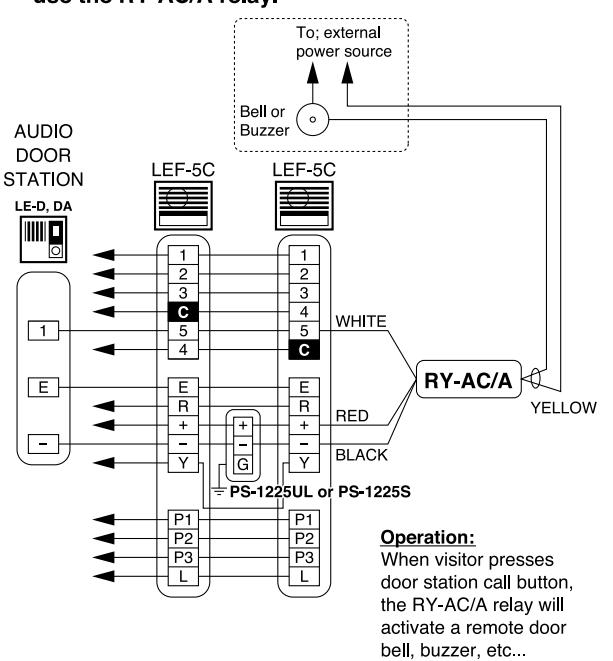
(6) RY-AC connection;
To activate a remote doorbell with the LEF-C system, use the RY-AC/A relay.
(7) Music speaker connection;
To receive music through a remote music speaker, connect 2 wires to S and E terminals on LEF-C masters and LE-C, LE-CN subs.
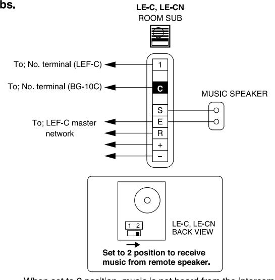
When set to 2 position, music is not heard from the intercom station, but all-call announcement can be received.

| * Power source: | DC 12V. Use PS-1225UL or PS-1225S power supply. | DC 12V. Use PS-1225UL or PS-1225S power supply. | |||
|---|---|---|---|---|---|
| * Current consumption: | Max. 300mA per station | ||||
| * Power output: | Max. 800mW at 20 ohm (reception) Max. 500mW at 20 ohm (transmission) | ||||
| * Calling: | From master to master / sub; by voice or electronic mono tone From LEF-1C to master; by all call announcement | ||||
| * Communication: | Press-to-talk at calling master. Handsfree communication at door, sub and receiving master. | ||||
| * Wiring: | Master Stations: Communication only: 5 common wires plus 1 per station in the system, looped. Comm. and All Call: 8 common wires plus 1 per station in the system, looped. Comm., All Call, Door Release: 9 common wires plus 1 per station in the system, looped. Standard Sub: 2 common wires plus 1 per station on the loop LE-C/CN: 4 common wires plus 2 per station on the loop Single Master System: 2 wires per sub, homerun. | ||||
| * Wiring distance: | Between two farthest master stations or master and each sub; | ||||
| AWG 24AWG 22AWG 20AWG | 18AWG | ||||
| Distance 400' 650' 1000' | 1600' | ||||
| Diameter 0.5mm 0.65mm 0.8mm | 1.0mm | ||||
| Distance 120m 200m 300m | 480m | ||||
| * Switching contact capacity for door release | AC 110V, 1A. DC 24V, 1A (selective door release or control of external devices), on output of RY-PA relay. | ||||
|
DC 12V, 1A | ||||
| * Dimensions & weight: |
LEF-3C, LEF-1C;
210 x 155 x 35 (mm); 8-1/4"H x 6-1/8"W x 1-3/8"D, Approx. 470g (1.04 lbs.) LEF-5C, LEF-10C; 240 x 200 x 35 (mm); 9-7/16"H x 7-7/8"W x 1-3/8"D LEF-5C Approx. 680g (1.50 lbs.) LEF-10C Approx. 750g (1.65 lbs.) |
||||
air air air air air air air air air air
WARRANTY Aiphone warrants its products to be free from defects of material and workmanship under normal use and service for a pone year after delivery to the ultimate user and will repair free of charge or replace at no charge, should it become dupon which examination shall disclose to be defective and under warranty. Aiphone reserves unto itself the sole right to the final decision whether there is a defect in materials and/or workmanship; and whether or not the product is windle warranty. This warranty shall not apply to any Aiphone product which has been subject to misuse, neglect, accident, or to violation of instructions furnished, nor extended to units which have been repaired or altered outside of the factor warranty does not cover batteries or damage caused by batteries used in connection with the unit. This warranty covers repairs only, and any repairs must be made at the shop or place designated in writing by Aiphone. Aiphone will responsible for any costs incurred involving on site service calls. Aiphone will not provide compensation for any loss or concerning the products during use, or for any consequent inconvenience and losses the result. Aiphone warrants its products to be free from defects of material and workmanship under normal use and service for a period of one year after delivery to the ultimate user and will repair free of charge or replace at no charge, should it become defective upon which examination shall disclose to be defective and under warranty. Aiphone reserves unto itself the sole right to make the final decision whether there is a defect in materials and/or workmanship; and whether or not the product is within the warranty. This warranty shall not apply to any Aiphone product which has been subject to misuse, neglect, accident, or to use in violation of instructions furnished, nor extended to units which have been repaired or altered outside of the factory. This warranty does not cover batteries or damage caused by batteries used in connection with the unit. This warranty covers bench repairs only, and any repairs must be made at the shop or place designated in writing by Aiphone. Aiphone will not be responsible for any costs incurred involving on site service calls. Aiphone will not provide compensation for any loss or damage incurred by the breakdown or malfunction of its products during use, or for any consequent inconvenience and losses that may

http://www.aiphone.com/
AIPHONE CO., LTD., NAGOYA, JAPAN AIPHONE CORPORATION, BELLEVUE, WA, USA AIPHONE S.A.S., LISSES-EVRY, FRANCE