Aiphone IS Series Quick Start Programming Guide
Open the original PDF document
View PDF

IS SERIES
Hybrid System with IS-IPC
Connecting IS Local with IS Network Based Equipment
QuikStart Programming Guide

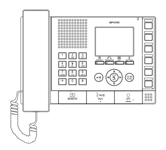
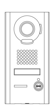
ATTENTION:
This is an abbreviated programming manual, addressing basic program settings for an IS Series Hybrid (Local + IP) System. A complete set of instructions (Standard (IP)
Operation Manual / Standard (IP) Settings Manual) can be found on the CD provided with the IS-IPMV, IS-SOFT, or IS-CCU.
Terminology
Area An Area defines a location description to a common group of stations. Example: "High School,"
"Front Office," or "Warehouse."
Site A Site in an IS system is a LAN which contains a single Host and up to 31 Clients. While the
IS system can have up to 32 Sites, this guide only covers a single Site system.
Host A Host is the unit in an IS Site containing a configuration file used to control how each device in the
Site behaves. Any IS-IPC, IS-IPMV, IS-IPDV, or IS-IPDVF can be a Host.
Client A Client is a unit in an IS Site that does not contain a complete configuration file, and relies on the Host
for operational instructions. Any IS-IPC, IS-IPMV, IS-IPDV, IS-IPDVF, or IS-SOFT can be a Client.
DHCP DHCP (Dynamic Host Configuration Protocol) allows all DHCP configured devices to ask for an IP address
when it powers on. In the context of an IS system, Clients may be DHCP, but a Host should always be Static. DHCP with a reservation configured by the DHCP server is possible, but not recommended.
LAN A LAN (Local Area Network) is typically managed by a DHCP enabled router. Anything connected to the
WAN port of the router is considered outside the Local Area Network. While there are numerous ways of connecting multiple LANs together, the only supported network layout for this guide is a LAN or a VPN.
VPN A VPN (Virtual Private Network) is a method of allowing two isolated LANs to communicate with each
other through a public network without losing privacy. For the purposes of the IS system, it can be
considered a single LAN.
IGMP IGMP (Internet Group Management Protocol) is the protocol used by Multicasting systems, including
the IS system. This protocol must be supported by and enabled on the networking hardware.
Multicast Multicasting is a method of communicating a single stream of information, such as video or paging
announcements, from a single host to many hosts. This saves bandwidth compared with sending the same packets to each recipient one at a time. The IS system uses Multicast for video during the call-in, but not when a master monitors the door (since it is the single recipient when the MONITOR button is used).
General Precautions
HOW TO USE THIS GUIDE
This guide is intended to be used for a single site IS Hybrid system running on a IPV4 network that includes an IS-IPC control unit, IS-IP door stations, IS-IPMV master stations, and IS-SOFT PC master stations.
Note: Refer to the IS Series Standard (IP) Setting Manual when using a IPV6 network or when multiple sites are required.
IMPORTANT:
When changes are made while programming, click Temporarily stored to save data prior to leaving each screen. The saved data will be applied to the system when the system is updated.
Step 1: System Layout
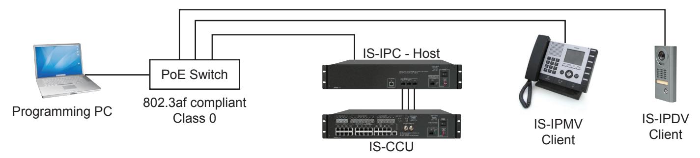
It is recommended that the IS-IPC be set as the Host . All other devices will be set as Clients . The final network needs to be a LAN or a VPN that supports Multicast. To program, use a network switch and CAT-5e cable to connect the PC to each device one at a time. When using a PoE switch, an 802.3af compliant PoE Class 0 switch is required.
Wiring Example:
Step 2: Configure PC's IP Address (not required if using a DHCP server)
The default IP address for each IS-IP device is https://192.168.0.40 . The PC will need to be set in the same subnet in order to connect to the IS-IP devices.
A. Open Control Panel
- - Windows® XP (classic view) Network Connections Double click Local Area Connection to open Connection Status window.
- - Windows® 7 (Category View) Network and Internet View network status and tasks Click Local Area Connection to open the Local Area Connection Status window.
- - Windows® 8 (Category View) Network and Internet View network status and tasks Click the active network adapter to open the Local Area Connection Status window.
- B. Click the Properties button to open Local Area Connection Properties window.
- C. Scroll down and left click Internal Protocol (TCP/IP) then click Properties button to open Internet Protocol Properties window.
- D. Select the Use the following IP address radio button. Type in the IP address 192.168.0.100 (the last number can be any valid host address except 40) and change the subnet mask to 255.255.255.0 . Click [OK].
- E. Click [OK] in the Connection Properties window to accept these changes.
Step 3: Log into IS-CCU (if using the IS-CCU)
When using the IS-CCU with the IS-IPC, the IS-CCU will need to be changed from a "local" system to an "IP" system.
- A. Open a web browser and point the address bar to https://192.168.0.30 . If using DHCP, enter the unit's IP address discovered with the IS_IPSEARCH program and hit [Enter]. Note: ensure that https (for security) is being used in the address bar.
- B. A security certificate error message will appear. Click "Continue to this website."
- C. Choose preferred language.
- D. Log in to the unit using the default administrator ID "aiphone," and default password "aiphone".
- E. Click the Standard system (IP system) radio b utton.
Figure 3.1: System configuration setting

- F. Click Temporarily stored to save changes.
- G. Click Updating the system from the menu on left.
- H. Click Update to update the IS-CCU unit with all stored data.
Step 4: Install and Configure IS-SOFT Application (OPTIONAL)
Note: IS-SOFT is not required to program the system. If using IS-SOFT, the application requires a PC with speakers and a microphone , or a headset in order to communicate with the stations in the system. A USB style microphone / headset is recommended.
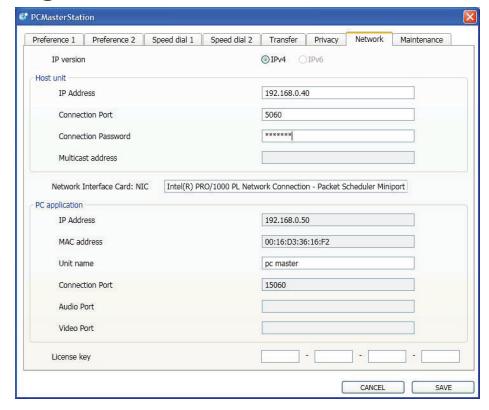
- A. Click the Setting button and click the Network tab.
- B. Enter the Host's IP address, the Connection password "aiphone" and choose the Network Interface Card from the drop down list. Enter the license key provided in the CD case (limit one per PC).
- C. Click Save .
IMPORTANT:
The software will attempt to make contact with the Host, but will give an error message because the Host isn't set up yet. Ignore this error and proceed to Step 5: Log in to IS-IP Device .
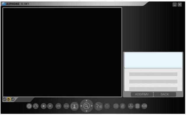
Note: Please register the IS-SOFT. See Step 14.
Figure 4.1: IS-SOFT Figure 4.2: Network Tab
Step 5: Log in to IS-IP Device (IS-IPC, IS-IPMV, IS-IPDV, IS-IPDVF)
IMPORTANT:
By default, the IS-IP devices will be set to DHCP. If using DHCP, use the IS_IPSEARCH program found on the CD to identify the IP address of the units. When not tied to a DHCP network, the units will have the default address of 192.168.0.40. By default, all units have the same address, making it important to hook up and program each station one at a time.
- A. Open a web browser and point the address bar to https://192.168.0.40 . If using DHCP, enter the unit's IP address discovered with the IS_IPSEARCH program and hit [Enter]. Note: ensure that https (for security) is being used in the address bar.
- B. A security certificate error message will appear. Click "Continue to this website."
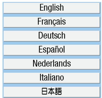
- C. Choose preferred language (see Figure 5.1 ).
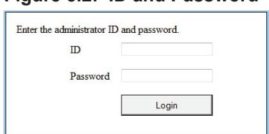
- D. Log in to the unit using the default administrator ID "aiphone," and default password "aiphone" (see Figure 5.2 ).
Figure 5.1: Select Language Figure 5.2: ID and Password
Step 6: Set Up Client Devices
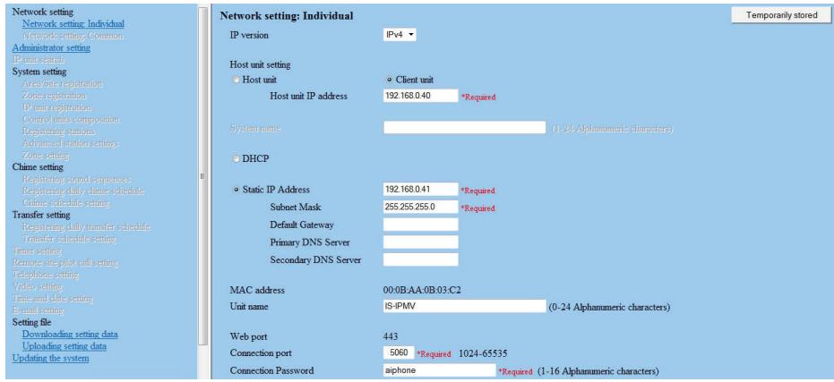
- A. Select Network setting from the menu on left.
- B. Click the Client unit radio button.
- C. Enter the Host unit IP address (This will be the Static IP address assigned to the host unit in Step 7).
- D. By default DHCP is utilized. Aiphone recommends assigning a static IP address by clicking the Static IP Address radio button and entering a unique IP address and Subnet Mask. (see Figure 6.1 )
- E. Enter a Unit name for the device (This is used for identifying the unit in programming only).
- F. Enter the Connection port and the Connection password for the system.
- G. Click Temporarily stored to save changes.
- H. Select Updating the system from the menu on left. Repeat Steps 5 & 6 for all client devices, then do Step 5 to log in to the host.
Figure 6.1: Network Setting - Client
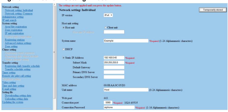
Step 7: Set Up Host Device
- A. Select Network setting from the menu on left.
- B. Click the Host unit radio button.
- C. Enter the System name (max. 24 alphanumeric characters).
- D. By default DHCP is utilized. Aiphone recommends assigning a static IP address by clicking the Static IP Address radio button and entering a unique IP address and Subnet mask (see Figure 7.1 ).
- E. Enter a Unit name for the device (This is used for identifying the unit in programming only).
- F. Enter the Connection port and the Connection password for the system.
- G. Click Temporarily stored to save changes.
Figure 7.1: Network Setting - Host
Step 8: IP Unit Registration - Host
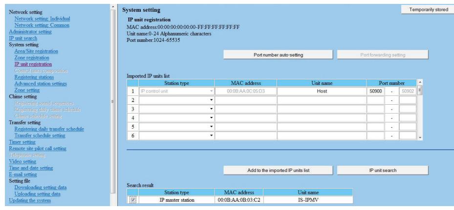
- A. Select IP unit registration from the menu on left.
- B. Scroll down and click IP unit search in the lower right (see Figure 8.1 ).
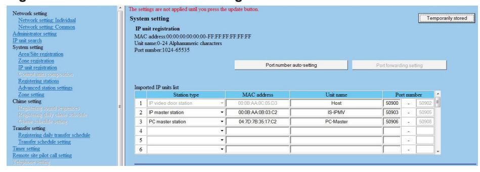
- C. Check the station(s) needing to be added to the Imported IP units list . Click Add to the imported IP units list to add them. Any units not appearing can be manually entered (see Figure 8.2 ).
Figure 8.1: IP Unit Registration - IP Unit Search Figure 8.2: Manual Entry
| Station type | MAC address | Unit nam | ||
|---|---|---|---|---|
| 1 | IP control unit | - | 00:0B:AA:0C:05:D3 | Host |
| 2 | IP master station | - [ | 00:0B:AA:0B:03:C2 | IS-IPMV |
| 3 | PC master station | - | 04:7D:7B:35:17:C2 | PC-Maste |
| 4 | IP control unit | |||
| 5 | IP master station | |||
| 6 | IP video door station PC master station | i i |
- D. Click Port number auto-setting to assign the required ports to all stations that need to communicate (see Figure 8.3 ).
- E. Click Temporarily stored to save changes.
Figure 8.3: Port Number Auto-setting
Step 9: Control Units Composition
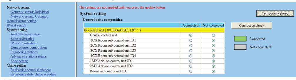
- A. Select Control units composition from the menu on left.
- B. For each IS-IPC in this Site, select which control units will be used (see Figure 9.1 ). Each IS-IPC can connect to a single IS-RCU or an IS-CCU with up to 2 IS-SCU and 4 IS-RCU control units.
- C. Click Temporarily stored to save changes.
Figure 9.1: Control Units Composition
Step 10: Registering Stations
- A. Select Registering stations from the menu on left.
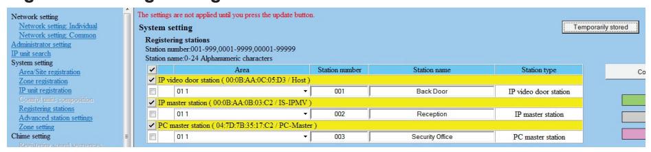
- B. The Registering stations table will be populated based on the settings made in Steps 8 & 9 . Enter a Station number and Station name for each door/master unit (see Figure 10.1 ).
- C. Click Temporarily stored to save changes.
Figure 10.1: Registering Stations
Step 11: Advanced Station Settings
- A. Select Advanced station settings from the menu on left.
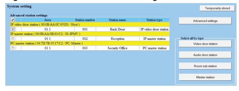
- B. The Advanced station settings table is populated based on the stations registered in Step 10 (see Figure 11.1 ).
- C. To program a door, check box and click Advanced settings . A new window will open. If multiple units need to call the same master station(s), check appropriate units and click Advanced settings .
Figure 11.1: Advanced Station Settings
D. Click Called stations (see Figure 11.2 ). A new window will open.
Figure 11.2: Advanced Settings Video Door Station

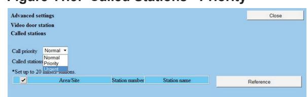
E. Select the Call priority level from the drop-down list (see Figure 11.3 ). Click Reference to open a new window to select the masters to be called (see Figure 11.4 ). Once the masters have been selected, click Close .
Figure 11.3: Called Stations - Priority Figure 11.4: Called Stations
| *Check the stations you want to add, then press [Close] button. | ||||||
|---|---|---|---|---|---|---|
| ~ | Area | Station number | Station name | Station type | ||
| ~ | IP video door station ( 00.0B:AA:0C:05:D3 / Host ) | |||||
| ~ | IP master station ( 00:0B:AA:0B:03:C2 / IS-IPMV ) | |||||
| V | 01 1 | 002 | Reception | IP master station | ||
| ~ | PC master station (04:7D:7B:35:17:C2 / PC-Master) | |||||
| V | 01 1 | 003 | Security Office | PC master station | ||
- F. Click Close to go back to the main Advanced station settings window.
- G. Repeat Steps C through G for all door stations.
- H. Click Temporarily stored to save changes.
Step 12: Time and Date Setting
- A. Click the Time and date setting from the menu on left.
- B. If the PC's date and time is correct, click Synchronized with PC . If not, set it manually then click Manual setting (see Figure 12.1 ).
Figure 12.1: Time and Date Setting

Step 13: Updating the System
- A. Click Updating the system from the menu on left.
- B. Click Update to update the unit with all stored data. The system will restart with all updated information. The update may take up to 10 minutes. The update will be complete when the LEDs on all door stations and master stations stop flashing.
Step 14: Register Products (Recommended)
We recommend that the IS hardware and IS-SOFT be registered. This will enable Aiphone to send alerts to the end user of firmware and software updates. Registering the software will also enable Aiphone to easily retrieve the License Key for the IS-SOFT should it ever be misplaced. Please use the following website to register all products in the installation. Register the products using the end user's contact information . www.aiphone.com/IS Sys Reg.htm
Troubleshooting
| Problem | Possible Cause | Solution | ||
|---|---|---|---|---|
| Secure address | Make sure you are typing "https://" and then the unit's IP address in the address bar of your | |||
| Can't access IS IP | prefix | browser. | ||
| device | IP range not the | Make sure your PC and the devices are in the same IP range (step 2 in this guide). | ||
| same | Disable WiFi and any additional Network Interface Cards on the PC. | |||
| Multicast not | IS_IPSearch utilizes multicast to search for and retrieve the IS-IP device's IP and MAC | |||
| enabled | address. Enable multicast address 239.197.40.41 on your network. | |||
| IS_IPSearch not | The IS_IPSearch program will search within the PC's domain, then filters results via MAC | |||
| working | IP range not the | Address. If IS_IPSearch does not find the IS-IP devices, | ||
| same | ensure that the PC is set to the same IP range as the IS-IP devices | |||
| (default range is 192.168.0.xxx). | ||||
| No video from IP door station when calling | Multicast address issue | In the event the IS-IPDV/F is able to call in and establish an audio connection to the IS-MV, IS-IPMV, or IS-SOFT master stations, but fails to establish video, this is a sign that the video multicast address is not being routed*. The specific multicast address used for video broadcast from the door to master is 239.0.1.4 (Network Settings: Common). This address must be routed between subnets for the system to work correctly. | ||
| * Note: When a master calls a door station, video most likely will be present. This is because master to door calls utilize unicast. | ||||
| Steady Amber | Standby mode | |||
| Flashing Amber | Applying setting changes after programming | |||
| Door station LED | Steady Red | Network / connection issue | ||
| indication | Flashing Red when call button pushed | Door station has a connection but is not programmed to call a master (step 11) | ||
| Solid Green | Active Communication | |||
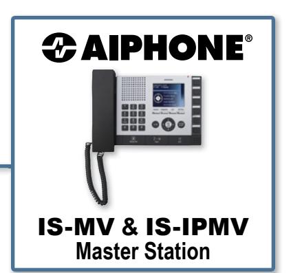
This operation guide describes the basic functions of your IS Series Master Station
For a complete operation manual (1.61 MB), scan QR code to download it from the manufacturer's website: www.aiphone.com/is-op-man

Operation Buttons
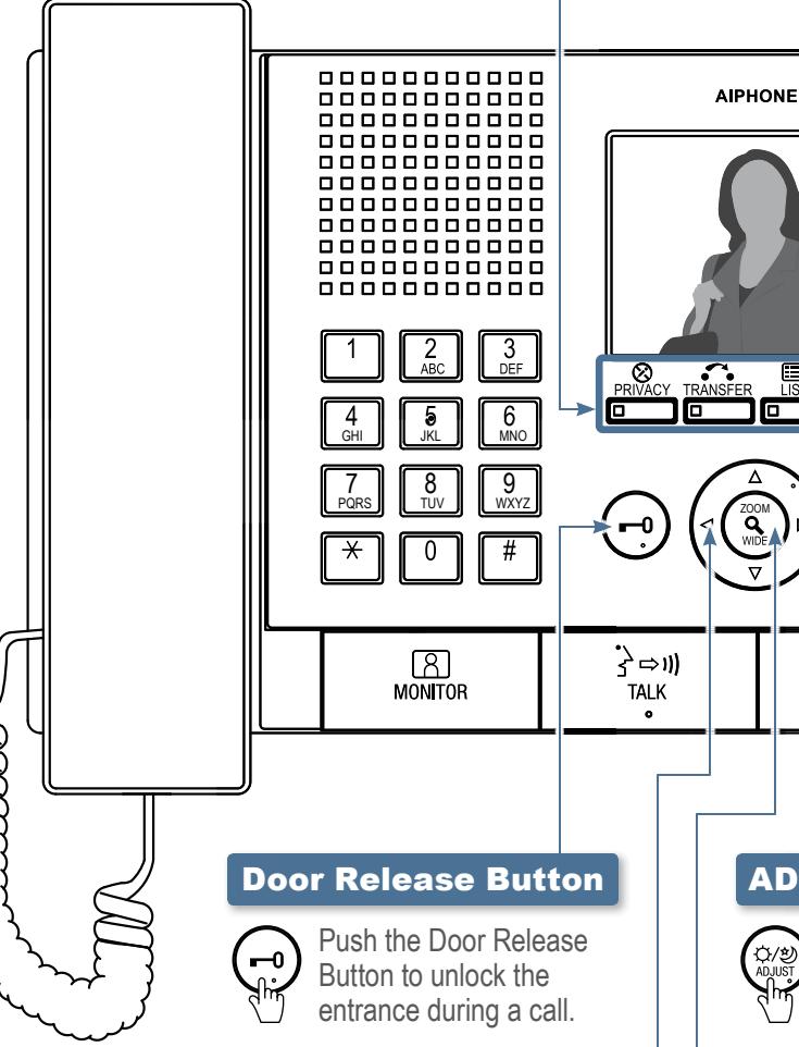
There are three privacy settings: OFF, 1, and 2. If set to OFF, a call from another master station can be answered by a voice response. If set to 1, a call from another master station can be answered by pushing the TALK Button or picking up the Handset. If set to 2, a call from another master station will provide a sound notification to you and the caller, indicating the station is in "do not disturb" mode. Push the PRIVACY Button to activate the selected setting (a red LED on the button remains lit when the feature is activated).
To manually send an answered call to another master station within the system, push the TRANSFER Button and select a destination (a red LED on the button blinks when transferring). To automatically send incoming calls to another master station within the system (CALL TRANSFER), push the TRANSFER Button to select your transfer options (a red LED on the button remains lit when the feature is activated).
Push the LIST Button to view stations and zones within the system. Use the Camera / Cursor Control and ZOOM/WIDE Buttons to make selections.
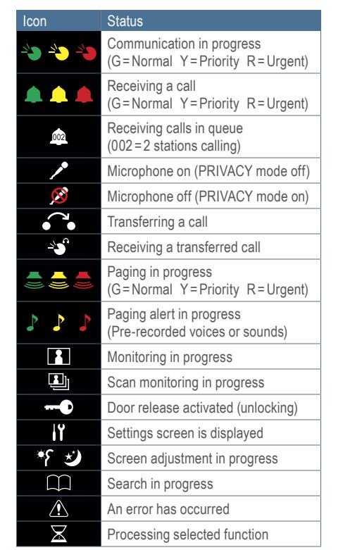
Push the SETTING Button to view all setting options for your specific master station. Use the Camera/Cursor Control and ZOOM/WIDE Buttons to make selections. A status icon appears on screen when a function is in operation (see chart below).
ADJUST Button
0FF

Push the ADJUST Button to compensate for low or bright backlight conditions when viewing video from a door station.
____
Camera/Cursor Control Button

Push , , , or to change the camera view (zoom-view only) or to scroll the cursor through the menu.
ZOOM/WIDE Button

Push the ZOOM/WIDE Button to change the screen view during a video call or while monitoring video. When scrolling through a menu, push the ZOOM/WIDE Button to make a selection.
This operation guide describes the basic functions of your IS Series Master Station
For a complete operation manual (1.61 MB), scan QR code to download it from the manufacturer's website: www.aiphone.com/is-op-man

Camera/Cursor Control and ZOOM/WIDE Buttons

See "IS-MV/IS-IPMV Master Station Operation Guide | 1 of 2" to read how the Camera/Cursor Control and ZOOM/WIDE Buttons operate.
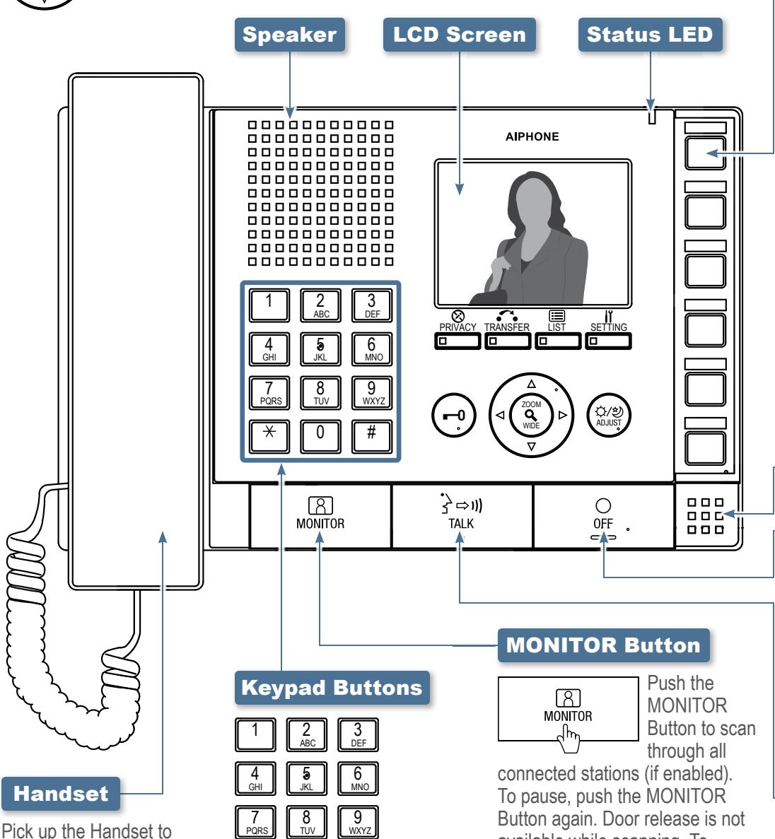
answer an incoming call or respond to an incoming page* Hang up the Handset to end the conversation. To make a call, search for the station or zone using the Keypad Buttons or the LIST Button. Once selected, push the TALK Button to establish the call. Pick up the Handset
for private communication.
Use the Keypad Buttons to search for a station or zone by number. To search by name, push the LIST Button and use the Camera/Cursor Control and ZOOM/WIDE Buttons to select name search. Once selected, use the Keypad Buttons to type the name of the station or zone.
connected stations (if enabled). To pause, push the MONITOR Button again. Door release is not available while scanning. To monitor a specific station, push the LIST Button and use the Camera/Cursor Control and ZOOM/WIDE Buttons to select a desired station. Once selected, push the MONITOR Button to begin monitoring activity where the station is located.
*Responding to a page while in broadcast mode is not an option.
Speed Dial Buttons
Speed Dial Buttons can be programmed to quickly select a station for calling and monitoring. They can also be programmed to quickly select a zone for paging. To program, use the SETTING Button. When programmed, push a Speed Dial Button to display the assigned station. To call/page the selected station at a normal priority level, push the TALK Button or lift the Handset. To call / page the selected station at a different priority level, push the ZOOM/WIDE Button to select the level before pushing the TALK Button. To monitor the selected station, push the MONITOR Button.
Microphone
OFF Button
Push the OFF Button to end a call (this does not turn off the
device). If in MONITOR mode, push the OFF Button to stop monitoring. If receiving a page, push the OFF Button to stop the page from going to your specific master station.
TALK Button
Push the TALK Button to answer an incoming call or respond to an
incoming page* Once answered, the conversation becomes hands-free. To make a call, search for the station or zone using the Keypad Buttons or the LIST Button. Once selected, push the TALK Button to establish the call.
This operation guide describes the basic functions of your IS Series PC Master Station Software
For a complete operation manual (1.25 MB), scan QR code to download it from the manufacturer's website: www.aiphone.com/soft-op-man
MAIN ENTRANCE


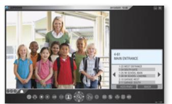
IS-SOFT PC Master Station Software
Talk Button

Click the Talk Button to answer an incoming call or respond to an incoming page* Once answered, the conversation becomes hands-free. To make a call.
search for the station or zone using the Keypad Buttons or the LIST Button. Once selected, click the TALK Button to establish the call. The spacebar also functions as the Talk Button.
*Responding to a page while in broadcast mode is not an option.
Off Button
Volume Button
Click the Volume Button
to view the digital volume
window. Once displayed.
Click the Keypad Button
to view the digital keypad
window. Once displayed,
use the Keypad Buttons
Speed Dial Buttons can
be programmed to quickly
select a station for calling
and monitoring. They
can also be programmed to quickly
use the Setting Button. When
programmed, click a Speed Dial
station. To call/page the selected
the Talk Button. To call/page the
station at a normal priority level, click
selected station at a different priority
level, click the Zoom/Wide Button to
Talk Button. To monitor the selected
select the level before clicking the
station, click the Monitor Button.
Button to display the assigned
select a zone for paging. To program,
adjust the call tone.
speaker, and microphone volumes
until the desired levels are reached.
Keypad Button
to search for a station or zone by
number. To search by name, click
the List Button and select the name
search option. Once selected, use
the Keypad Buttons to type the
name of the station or zone.
Speed Dial
Button

Privacy Button

There are three privacy settings: OFF, 1, and 2. If set to OFF, a call from
another master station can be answered by a voice response. If set to 1, a call from another master station can be answered by clicking the Talk Button. If set to 2, a call from another master station will provide a sound notification to you and the caller, indicating the station is in "do not disturb" mode. Click the Privacy Button to select the desired setting (the button remains lit when the feature is activated).
Transfer Button

To manually send an answered call to another master station within the system, click the Transfer
Button and select a destination (the button blinks when transferring). To automatically send incoming calls to another master station within the system (Call transfer), click the Transfer Button to select your transfer options (the button remains lit when the feature is activated).
Record Button
Monitor Button

Click the Monitor Button to scan through all connected stations (if enabled). To pause, click the Monitor Button again. Door release is not available while scanning.
To monitor a specific station, click the LIST Button and use the Camera/Cursor Control and Zoom/Wide Buttons to select a desired station. Once selected, click the Monitor Button to begin monitoring activity where the station is located.
Adjust Button

Click the Adjust Button to compensate for low or bright backlight conditions when viewing video from a door station.
Door Release Button

Click the Door Release Button to unlock the entrance during a call.
Play Button

Click the Play Button once to view the list of recorded images. Select the desired file and click the Play Button again to see the snapshot or motion JPEG video. Audio will play if the audio option was set to record along with the video images.

Click the Setting Button to view all setting options for your specific master station software. Use your computer
mouse to make selections. Click SAVE to keep any changes.
Camera/Cursor Control Button

Click ▲, ▼, ◀, or to change the camera view (zoom-view only) or to scroll the cursor through the menu.
Zoom/Wide Button
Click the Zoom/Wide Button to change the screen view during a video call or while monitoring video. When scrolling
through a menu, click the Zoom/Wide Button to make a selection.
List Button

Click the List Button to view stations and zones within the system. Use the Camera/Cursor Control and Zoom/Wide Buttons to make selections.
Setting Button

IS-SOFT Consumer Operation Guide | 1 of 1
January 2015