Aiphone BG-10C Installation Instructions
Open the original PDF document
View PDF

MUSIC & CHIME ADAPTOR
Model;
BG-10C
(Music, All-call & Chime adaptor for LEF-C and LEF systems)
INSTRUCTIONS
NAMES AND FUNCTIONS

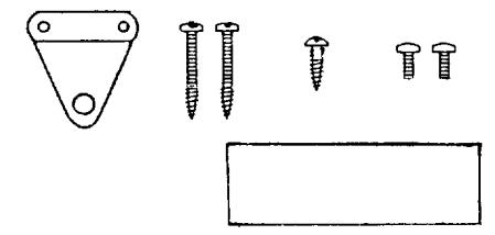
- * Mounting bracket
- * Operation seal(1)
- * Wood screw(2)
- * Wood screw & screw(2) (for attaching bracket)
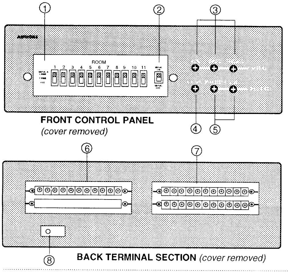
- 1 Music & Chime selector switch
- 2 Music ON/OFF switch
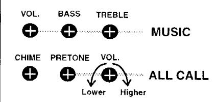
- 3 Music volume, Bass & Treble controls
- 4 Chime volume control
- (5) All-call Pretone volume and Speech volume controls
- ⑥ Terminals for power supply, music & door station connection
- 7 Terminals for LEF-C network (all call & music receiving)
- ® Cable clamp
2
FEATURES
-
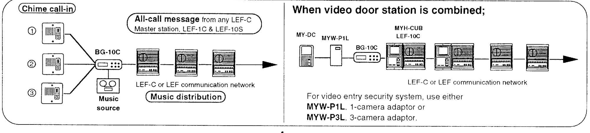
* BG-10C adaptor provides three functions for your LEF or LEF-C communication system.
- 1. All-call announcement from any LEF-C Room master Station(& LEF-10S, surface-mount and LEF-1C sub master station)
- 2. Music distribution (all-call & music can be received at all masters & LEF-1C, LE-C, CN subs)
- 3. Chime distribution for door station call-in

INSTALLATION GUIDELINES
For installation of LEF-C intercom & MY video systems, refer to Instructions for LEF-C & BGR-10A. According to the system configuration, make wiring diagram between BG-10C and the first LEF-C station.
* BG-10C works with only 2-wired PanTilt MY video system.
Coax-cabled camera adaptors MFW-P1 and MFW-P3B cannot be used with BG-10C.
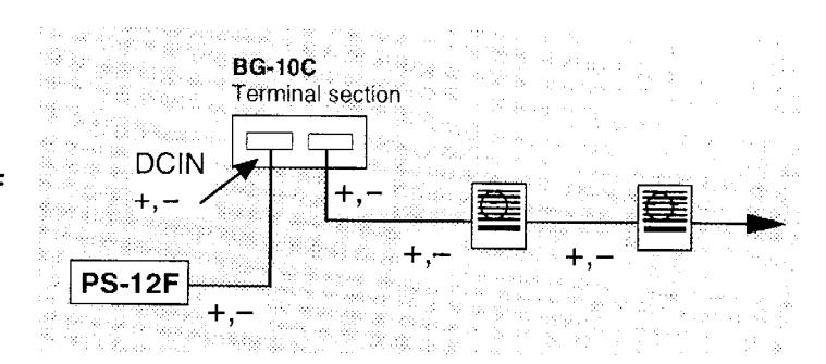
* Power supply;
Use one PS-12F power supply for an entire LEF-C and BG-10C adaptor.
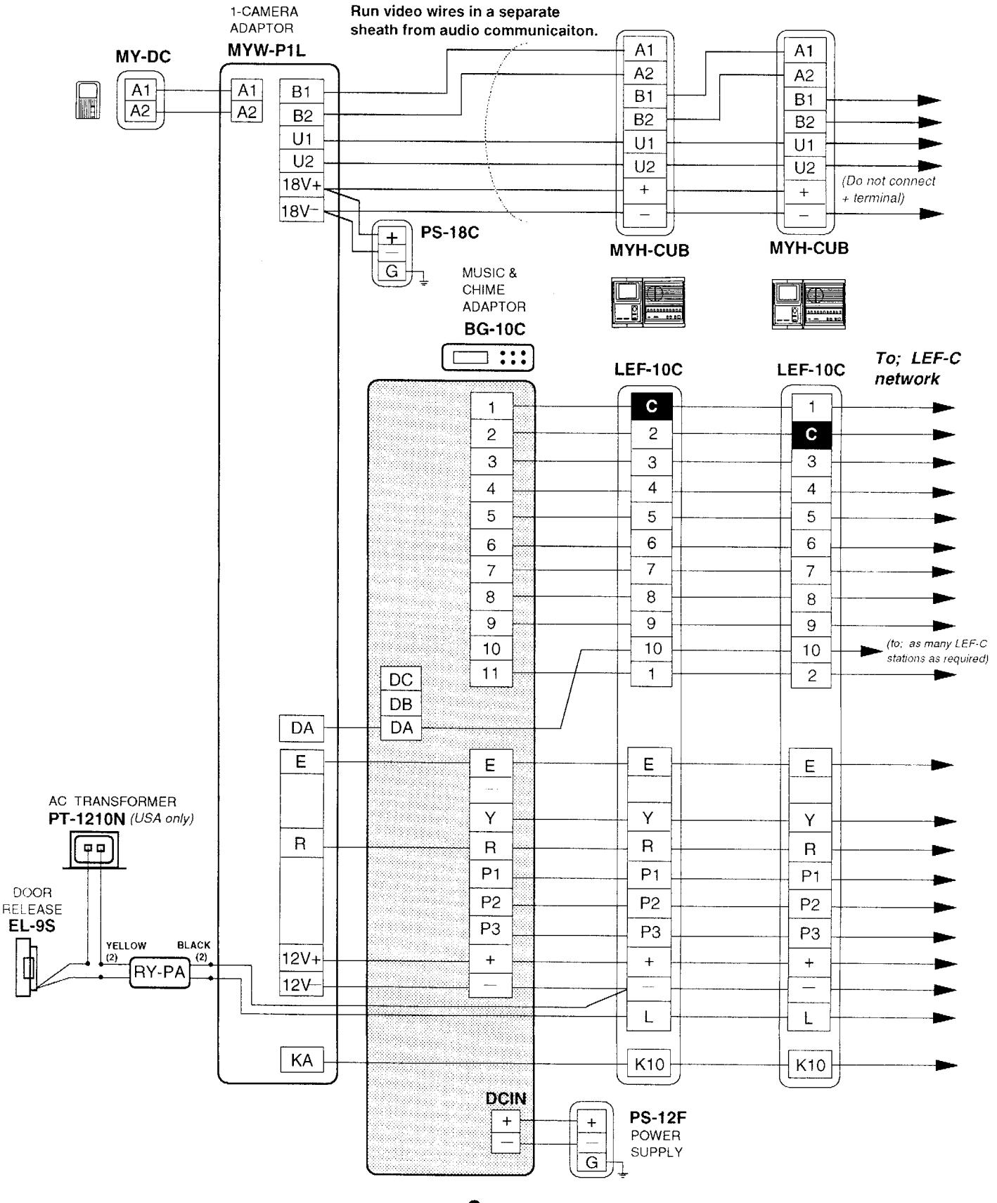
On BG-10C, connect +,- wires from PS-12F to DCIN +,- terminals, then extend power supply wires +,- to LEF-C network.
* Selector switches;
On BG-10C unit, 11 selector switches are provided to turn on/off music & chime tone for each LEF-C Room Station. After completing all the wirings, check if all MUSIC & CHIME selector switches are set properly.
* Music input voltage to AUX;
Rated input voltage to AUX terminal should not exceed 1V. If surpassed, it could cause sound distortion, intermittent transmission or unit failure.
* Do not open the case;
Do not open the case while BG-10C is powered. Some components inside the unit are warm while operational.
* Surface temperature;
During operation, it is possible that BG-10C's housing surface temperature could be warm to the touch. This a normal occurrence.
* Incorrect wiring;
Strictly observe the wiring polarity. Never connect PS-12F +,— power supply wires to any other terminals than DCIN +,— on BG-10C. If PS-12F +,— wires are wrongly connected to 1 11 and E, or to P2 and P3 on BG-10C, it could cause system disorder and severe damage to BG-10C. If +,— wires on BG-10C would be connected to No.(1 10) terminals on LEF-C unit, it could cause damage to LEF-C unit.
* Door station calling;
If a door station calls in while a unit is in the all-call mode, the chime will be heard through all of the stations, regardless of the position of each music/chime on/off switch.
* Installation locations;
Select the installation locations that would not be exposed to temperature/humidity extremes, water, oil, dust, iron dust, inflammable and chemical products, etc.
It is suggested that BG-10C unit and wiring be kept more than 2m(7') away from a radio, etc., as it may pick up chime call tone.
MOUNTING GUIDELINES
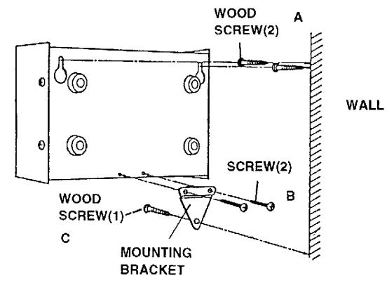
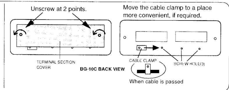
Attach the mounting bracket with the two screws B (supplied) on back of chassis.
Fasten the two screws A(supplied) on the wall, with a space of 220 mm( 8-5/8"), protruding approximately 10 mm( 3/8") from the wall. Hook the BG-10C unit onto the screws and pull the unit downward until it locks in place. Pass wires through cable clamp. Connect wires on terminal section. Fix the mounting bracket with the wood screw C. Attach terminal cover.

TERMINAL IDENTIFICATION
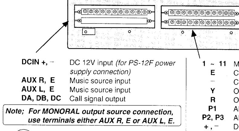
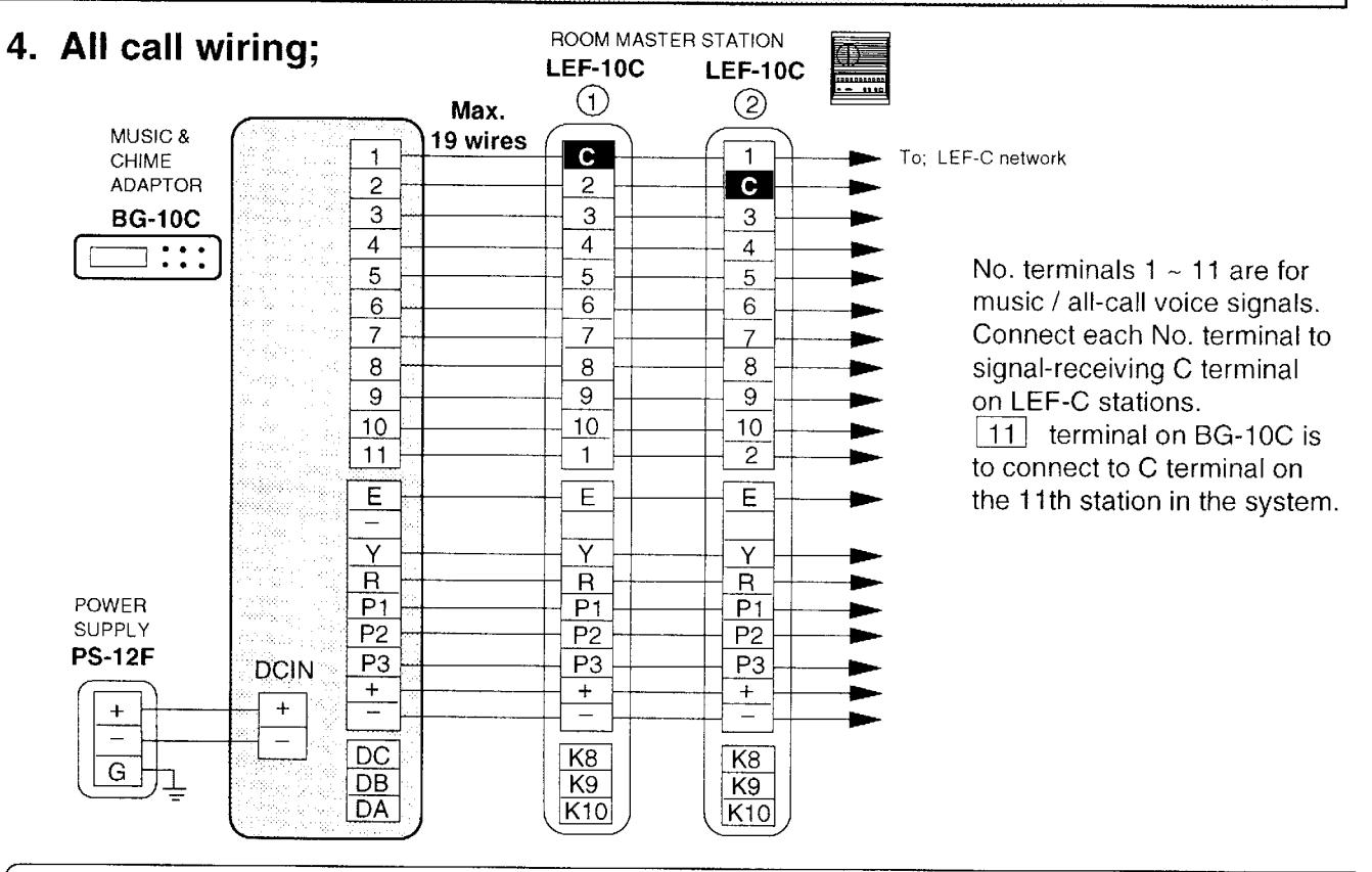
1 ~ 11 Music & all-call signal output to each station
BG-10C BACK VIEW (cover is removed)
E Common communication
Common negative
Y Occupied mode control during all call
R Occupied mode controlP1 All call activation control
P2, P3 All call communication input
+, - DC 12V output(for LEF-C communication network)

WIRING DIAGRAMS
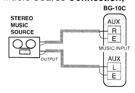
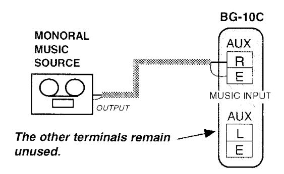
1. Music Source Connection;

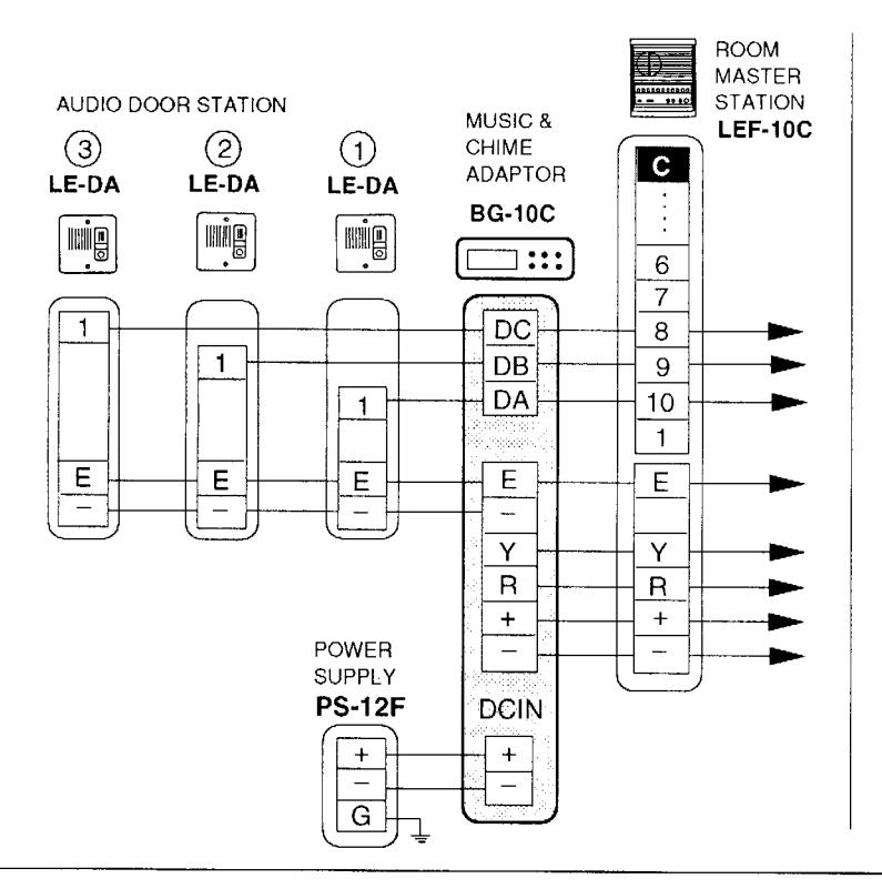
2. Door Station Connection;
NOTES;
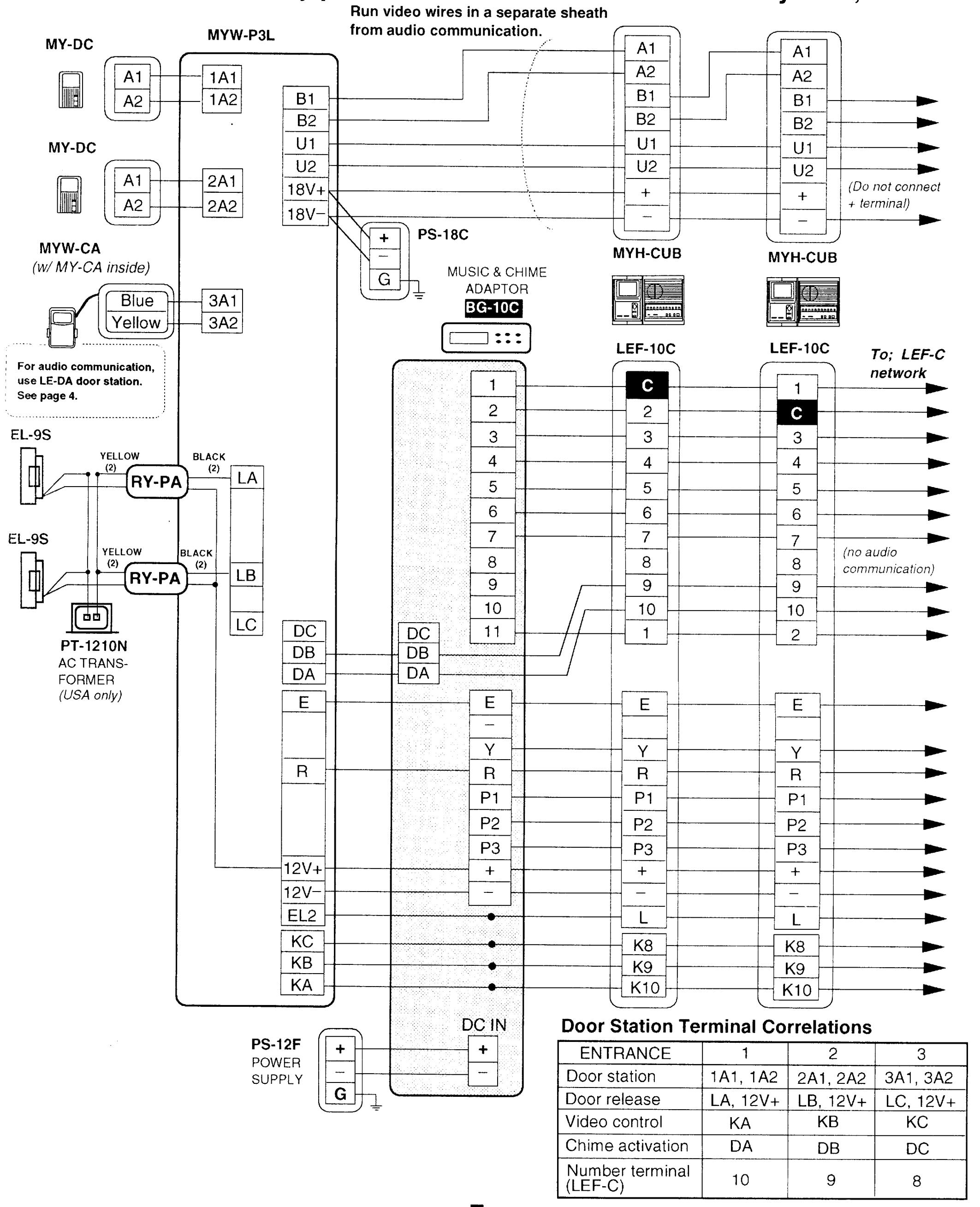
- 1 Max. 3 door stations can be connected to BG-10C & LEF-10C network.
- 2 Use LEF-C No. terminal for each door station;
DA - 10 for door #1 DB - 9 for door #2 DC - 8 for door #3
3 Connect to as many LEF-C room master stations as required(limited only by system capacity) for door station chime call-in(Chime is heard only when BG-10C is used).
3. Music Speaker Connection
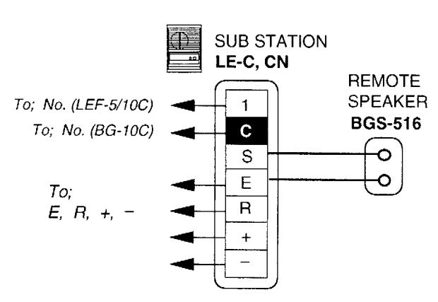
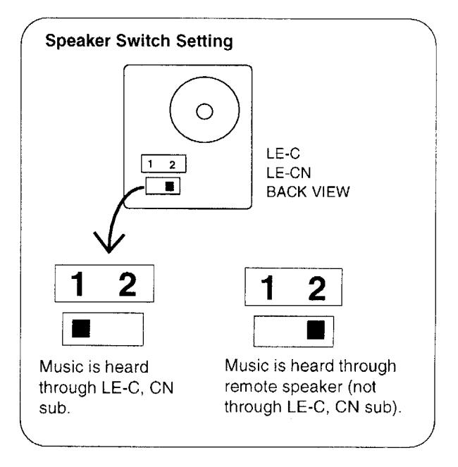
LE-C, CN sub station has C terminal, to be connected to BG-10C for music & all-call reception. If a remote speaker is installed for music reception at an LE-C/CN sub station, extend two wires from S, E terminals to remote speaker. (communication and all call are still received through LE-C/CN speaker)

BG-10C OPERATIONAL SETTINGS ;
For music distribution;
1 Put MUSIC switch to ON position. Turn on power of music source. Music is distributed through all of the connected LEF masters, LEF-1C sub master and LE-C/CN subs speakers. If music is not required at a particular station(s), set the MUSIC/CHIME selector switch to OFF or CHIME only position.
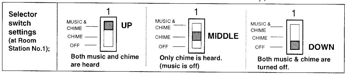
- 2) Music mutes automatically during station-to-staiton communication or All call.
- 3 Put MUSIC switch to OFF position to cut off music throughout the system.
For all call;
Initiate all call at one LEF-C master station or at LEF-1C sub master station. Depress ALL CALL switch, which produces pre-tone through all of LEF masters, LEF-1C & LE-C/CN subs. Send message while depressing and holding TALK button. Depress ALL CALL switch, and the switch is released. (on LEF-1C only, press and keep pressing ALL CALL switch to send message)
Turn control clockwise to increase each volume, treble and bass.
- * Do not initiate all call or any other operation, while Occupied LED is lit.
- * During room-to-room communication, call in from door station is annunciated by chime tone. Terminate present communication by depressing OFF button. Then depress a corresponding number button with a lighted LED to reply to door station.

5. LEF-10C & One Entry PanTilt MY Video system;

6. LEF-10C & 2-Entry plus Surveillance PanTilt MY Video System;

SPECIFICATIONS
| * Power source: |
[
E |
DC 12V. Use PS-12F power supply for entire LEF-C system and BG-10C adaptor | |||||
|---|---|---|---|---|---|---|---|
| * Current consumption: | l l | Max. 1.5A (music, chime & all-call) Max. 2.5A (music maximum output) 0.1A (standby) | |||||
| * All-call initiating station: | From LEF-3C, LEF-5C, LEF-10C and LEF-10S (surface) master stations, and LEF-1C sub master station | ||||||
| * All-call receiving station: | A | All master stations, and LEF-1C sub master & LE-C, CN sub stations | |||||
| * No. of door stations: | N | Max. 3 door stations (audio or audio /video) | |||||
| * Maximum intercom stations: | 1 | 11 stations (room master + door station) in total | |||||
| * Wiring: |
(r
3 (r 7 |
19 wires between BG-10C and LEF-10C (max. in all-master system w/11 LEF-10C) 3 wires between BG-10C and each door station (max. 3 door stations per system) 7 wires between BG-10C and MYW-P3L, 3-camera adaptor (when 3 video door stations are installed) | |||||
| * Wiring distance: | * | AWG Distance Diameter Distance Between door AWG Distance Distance Diameter |
24AWG
300' 0.5mm 90m |
22AWG
500' 0.65mm 150m |
20AWG
750' 0.8mm 230m |
18AWG
1180' 1.0mm 360m 18AWG 1600' 1.0mm |
|
| Distance | 120m | 200m | 300m | 480m | |||
| * Dimensions & weight: (H x W x D) |
165 x 250 x 77mm; 6-1/2" x 10" x 3"
Approximately 1,800g (3.97 lbs.) |
||||||
ijŦŶĸŶĸŶĸŶĸŶĸŶĸŶĸŶĸŶĸŶĸŶĸŶĸŶĸŶĸŶĸŶĸŶĸŶĸŶĸ WARRANTY
Aiphone warrants its products to be free from defects of material and workmanship under normal use and service for a period of one year after delivery to the ultimate user and will repair free of change or replace at no charge, should it become defective upon which examination shall disclose to be defective and under warranty. Aiphone reserves unto itself the sole right to make the final decision whether there is a defect in materials and/or workmanship; and whether or not the product is within the warranty. This warranty shall not apply to any Aiphone product which has been subject to misuse, neglect, accident, or to use in violation of instructions furnished, nor extended to units which have been repaired or altered outside of the factory. This warranty does not cover batteries or damage caused by batteries used in connection with the product. This warranty covers bench repairs only, and any repairs must be made at the shop or place designated in writing by Aiphone. Aiphone will not be responsible for any costs incurred involving on site service calls.
Aiphone Co., Ltd., Nagoya, Japan
Aiphone Corporation, Bellevue, WA, USA