Aiphone AXW-AZ Series Installation Instructions
Open the original PDF document
View PDF

AXW-AZ
AX Series Video Adaptor for CCTV Camera and Audio Door Station
- INSTRUCTIONS -
The AXW-AZ converts a standard CCTV camera's signal to a CAT-5e connection, providing a signal compatible with the AX Integrated Security and Communication system. This allows the utilization of a color CCTV camera and a separate audio door station (AX-DM or IE/IF-Series) to be used in place of an AX video door station. A motion detector or other activation device can be connected to the Sensor input to trigger camera activation. Video output is provided for continual viewing and/or recording via composite pass-through. The unit is equipped with a relay output to trigger an external device, such as a DVR or video switcher whenever the audio and/or video to the AX system is active.
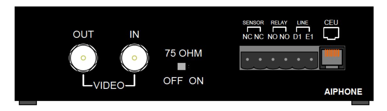
TERMINAL DEFINITIONS:
CEU (RJ-45): Output from AXW-AZ to AX CEU Door Station input LINE D1, E1: AX-DM or IE/IF-Series Audio Door Station input
RELAY NO, NO: Normally Open relay contact, activated when AX video is on.
SENSOR NC, NC: Normally Closed contact, activates call-in function and video at AX master
when tripped by motion detector or other device with N/C contacts.
VIDEO IN: Composite input signal from CCTV camera
VIDEO OUT: Composite output to external CCTV monitor, switcher, DVR, or video input on
another device
75 OHM SWITCH: Termination Switch. Set to OFF position when VIDEO OUT is connected to
CCTV system. Set to ON position when video output is not used.
COMPATIBLE AUDIO DOOR STATIONS:
AX-DM Mullion mount, black plastic
IF-DA Surface mount, brown plastic
IE-DC Surface mount, brown plastic w/aluminum
IE-JA Flush mount, 2 gang, stainless steel faceplate
IE-SS Flush mount, 2-gang, stainless steel vandal resistant
IE-SSR Flush mount, 2-gang, stainless steel vandal resistant w/red mushroom call button
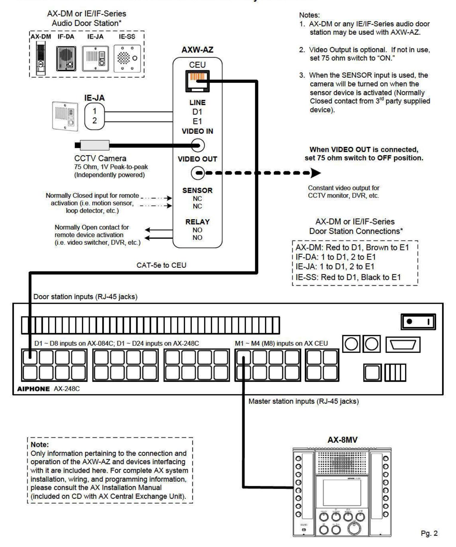
WIRING DIAGRAM:
AXW-AZ with Standard CCTV Camera and Audio-only Door Station
PROGRAMMING:
- 1. Follow standard AX programming procedures as described in the AX Installation & Operation manual (included on CD with the AX CEU).
- 2. When configuring door stations, be sure to set the station number corresponding to the AXW-AZ to "Video" in the AX setup utility.
| No. | Location Name |
Video
Audio |
Call
Level |
DR
Relay |
Scan
Monitor |
|---|---|---|---|---|---|
| 1 | Not Station | None | Normal | N.O. | Enable |
| 2 | Main Gate 02 | None | - ormal | N.O. | Enable |
| 3 | No3 Station | None | riolty | N.O. | Enable |
| 4 | No4 Station | Video | ormal | N.O. | Enable |
| 5 | No5 Station | Audio | ormal | N.C. | Disable |
| 6 | No6 Station | None | Priorty | NO. | Enable |
Typical configuration selection
OPERATIONS:
- 1. The AXW-AZ will function as a standard AX-series video door station, and can utilize all door station associated capabilities (i.e. Scan Monitor, Door Release, Priority Call Settings, etc).
- 2. If the SENSOR input is utilized, the AXW-AZ will generate a typical door station call indication at the associated master stations. The priority level will be as chosen in the AX setup utility.
SPECIFICATIONS:
Power: Supplied by AX CEU
Video Input & Output: Composite 1V Peak-to-Peak, NTSC
Connector: BNC
Audio Door input: Use AX-DM or any IE/IF-Series Audio Door Station
Relay: Normally Open contact output, 24V DC, 1A
Sensor: Normally Closed contact input
Wire: CAT-5e, 24AWG UTP-4
Wiring distance w/ Door: Max. 980' from AX-DM / IE/IF-series door to AX CEU
(through AXW-AZ)
Wiring distance w/o Door: Max 980' from AXW-AZ to AX CEU
Dimensions: 1-5/8"H x 7"W x 4"D
FCC Class B Verification
NOTE: This equipment has been tested and found to comply with the limits for a Class B digital device , pursuant to Part 15 of the FCC Rules. These limits are designed to provide reasonable protection against harmful interference in a residential installation. This equipment generates, uses, and can radiate radio frequency energy and, if not installed and used in accordance with the instructions, may cause harmful interference to radio communications. However, there is no guarantee that interference will not occur in a particular installation. If this equipment does cause harmful interference to radio or television reception, which can be determined by turning the equipment off and on, the user is encouraged to try and correct the interference by one or more of the following measures:
- Reorient or locate the receiving antenna.
- Increase the separation between the equipment and receiver.
- Connect the equipment into an outlet on a circuit different from that to which the receiver is connected.
- Consult the dealer or an experienced radio/TV technician for help.
Note:
Only information pertaining to the connection and operation of the AXW-AZ and devices interfacing with it are included here. For complete installation, wiring, and programming information regarding the AX system, please refer to the AX Installation Manual, which is included on the CD provided with the AX CEU.