Aiphone AXW-AVTR Series Installation Instructions
Open the original PDF document
View PDF

AXW-AVT / AXW-AVR
AX Series Audio-Video Adaptor for 3<sup>rd</sup> Party Transmission Equipment
- INSTRUCTIONS -
The AXW-AVT and AXW-AVR are designed to allow connection of a standard AX-series audio video door station (or audio-only IE-series door station) via the AXW-AVT, conditioning the signal for use with 3<sup>rd</sup> party transmission equipment (fiber optics, Ethernet, etc.) and converting it back via the AXW-AVR to a signal compatible with the AX-series exchange unit. External video input/output is provided at both adaptors to allow 3<sup>rd</sup> party camera input, output to recording devices, etc. A motion detector or other activation device can be connected to the Sensor input to trigger door / camera activation (AXW-AVT only). The units also feature a relay output to trigger an external device, such as a DVR or video switcher local to either the AXW-AVT or AXW-AVR whenever the audio and/or video is active. Alternatively, the AXW-AVT can be used to adapt an AX-series audio video door station to a standalone third party device (video server, network DVR, etc).
AXW-AVT
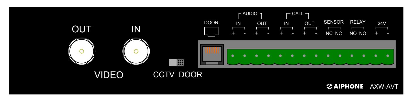
AXW-AVT TERMINAL DEFINITIONS:
DOOR (RJ-45 Jack): RJ-45 connection from AX-series audio video door, or spliced audio only door (IE/
IF-series).
AUDIO IN/OUT: Input / Output connections for audio transmission (line level, polarity indicated by
'+' and '-').
CALL IN/OUT: Transistor-switched input / output to be connected to relay input / output on
transmission equipment. 'Call In' indicates call placed by door station, 'Call Out'
indicates master-initiated activity (polarity indicated by '+' and '-').
SENSOR NC, NC: Normally Closed contact input, activates 'Call In' function when tripped by external
motion detector or other device with N/C contacts.
RELAY NO, NO: Normally Open relay contact, activated whenever communication is active. VIDEO IN: Composite input signal from CCTV camera, if used in place of AX-series audio
video door station.
VIDEO OUT: Composite output to external transmission equipment. Source dependent upon
CCTV / DOOR switch.
CCTV / DOOR SWITCH: Determines whether AX-series audio/video door station video ('DOOR' setting) or
external CCTV video ('CCTV' setting) will be present on 'VIDEO OUT' for
connection to external transmission equipment.
24V +, - 24V DC input (use Aiphone PS-2420UL).
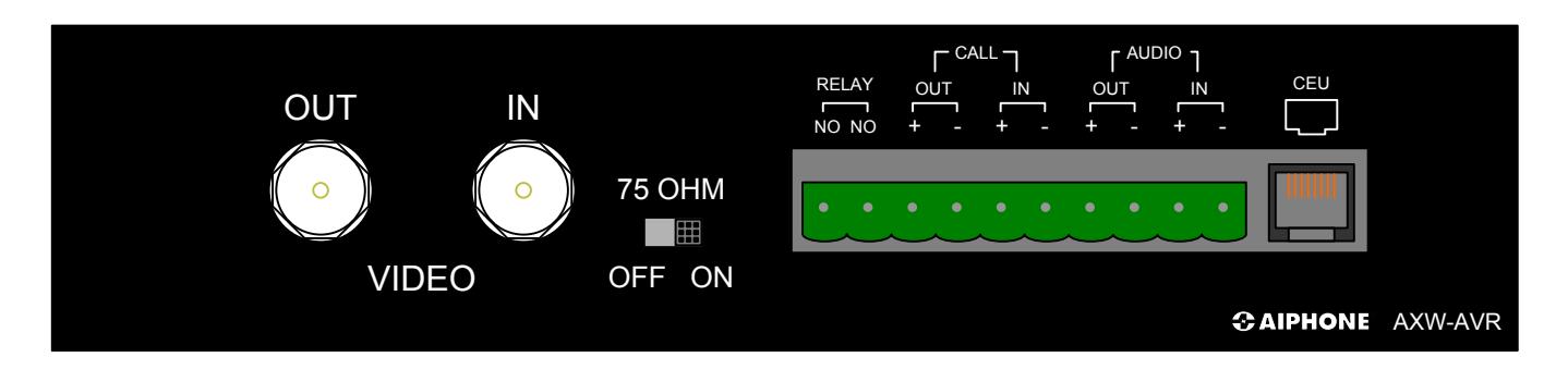
AXW-AVR TERMINAL DEFINITIONS:
RELAY NO, NO: Normally Open relay contact, activated whenever communication is active.
CALL IN/OUT: Transistor-switched input / output to be connected to relay input / output on transmission equipment. 'Call In' indicates call placed by door station, 'Call Out'
indicates master-initiated activity (polarity of input / output indicated by '+' and '-').
AUDIO IN/OUT: Input / Output connections for audio transmission (line level, polarity indicated by
'+' and '-').
VIDEO IN: Composite input signal from CCTV camera, if used in place of AX-series audio
video door station.
VIDEO OUT: Composite output to external transmission equipment. Source dependent upon
CCTV / DOOR switch.
OFF/ON SWITCH: Determines whether AX-series audio video door station video ('DOOR' setting) or
external CCTV video ('CCTV' setting) will be present on 'VIDEO OUT' for
connection to external transmission equipment.
CEU (RJ-45 Jack): RJ-45 connection from AXW-AVR to CEU, simulating a standard AX-series Audio/
Video door station.
COMPATIBLE DOOR STATIONS (AXW-AVT):
AX-DV Surface mount, die cast zinc, vandal resistant, Audio-Video AX-DVF Flush mount, stainless steel, vandal resistant, Audio-Video
AX-DM Mullion mount, black plastic, Audio Only IF-DA Surface mount, brown plastic, Audio Only
IE-DC Surface mount, brown plastic w/aluminum, Audio Only IE-JA Flush mount, 2 gang, stainless steel faceplate, Audio Only
IE-SS Flush mount, 2-gang, stainless steel, vandal resistant, Audio Only
IE-SSR Flush mount, 2-gang, stainless steel, vandal resistant w/red mushroom call button, Audio Only
PROGRAMMING:
- 1. Follow standard AX programming procedures as described in the AX Installation & Operation manual (included on CD with the AX CEU).
- 2. When configuring door stations, be sure to set the station number corresponding to the AXW-AVT / - AVR to "Video" in the AX setup utility.
|
Exchan-
ge No. |
No. | Location Name |
Video
Audio |
Call
Level |
F | ||
|---|---|---|---|---|---|---|---|
| ı | 1 | Main Gate #1 | Video | • | ormal | ||
| ı | 1 | 2 | Vestibule | None | ormal | ||
| ı | 3 | Front Cooridor |
Video
Audio |
ormal | |||
| ı | 4 | South Entry | ormal | ||||
| ı | 5 | North Entry | video | IN | formal | ||
| 6 | Video | Normal | |||||
Typical configuration selection
AXW-AVT / AXW-AVR with Meridian Technology Fiber (ST/SR-AiphoneAX1-XS), 1 of 2
Please Note:
Only information pertaining to the connection and operation of the AXW-AVT / AXW-AVR and listed 3rd party devices interfacing with it are included here. Aiphone is not responsible for attempts to connect the AXW-AVT / AXW-AVR to untested 3rd party transmission hardware. Consult the installation manual for the 3rd party device being utilized for further information regarding physical mounting, base functionality, power requirements, etc. For the most up-to-date compatibility information, please consult http:// www.aiphone.com or contact Aiphone Technical Support.
For complete AX system installation, wiring, and programming information, please consult the AX Installation Manual (included on CD with AX Central Exchange Unit, or available at http://www.aiphone.com).
AXW-AVT / AXW-AVR with Meridian Technology Fiber (ST/SR-AiphoneAX1-XS), 2 of 2
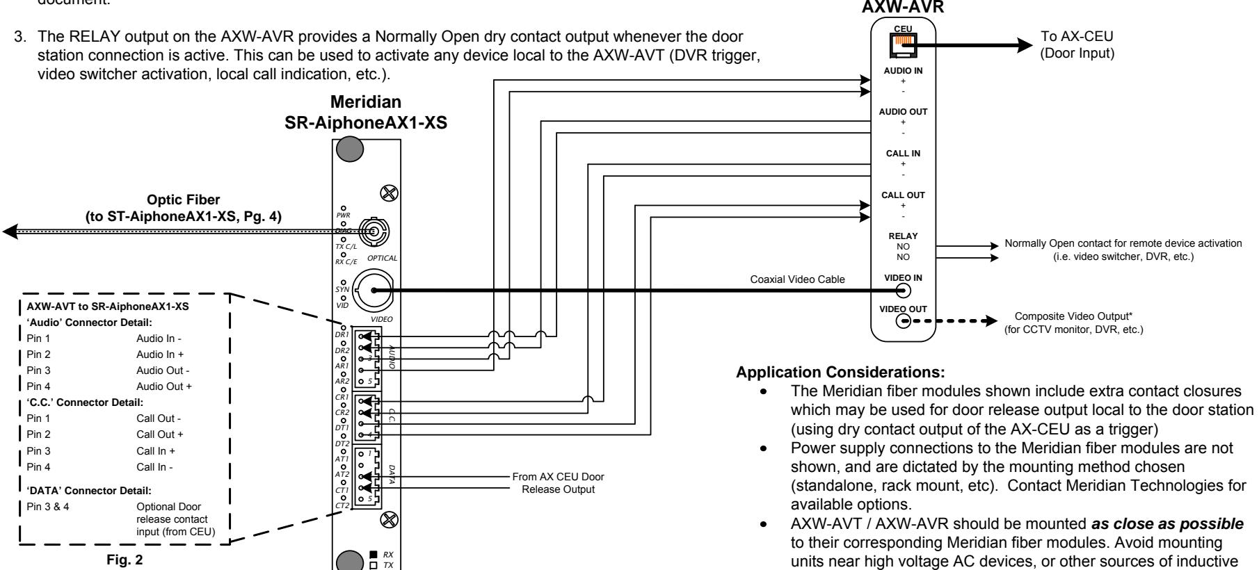
Configuration Notes (2 of 2):
- 1. Connect the AXW-AVR 'CEU' connection to an unused Door station input on the AX-CEU and ensure that the AX-CEU has been programmed to accept a video door station on that input (see Pg. 2).
- 2. Connect the Call In / Call Out and Audio In / Audio Out connections on the AXW-AVR to the Meridian fiber receiver module (as detailed below, Fig. 2). For complete pin definitions, consult the Meridian installation document.
Please Note:
Only information pertaining to the connection and operation of the AXW-AVT / AXW-AVR and listed 3rd party devices interfacing with it are included here. Aiphone is not responsible for attempts to connect the AXW-AVT / AXW-AVR to untested 3r d party transmission hardware. Consult the installation manual for the 3r d party device being utilized for further information regarding physical mounting, base functionality, power requirements, etc. For the most up-to-date compatibility information, please consult http:// www.aiphone.com or contact Aiphone Technical Support.
noise.
Pg. 5 Pg. 6 For complete AX system installation, wiring, and programming information, please consult the AX Installation Manual (included on CD with AX Central Exchange Unit, or available at http://www.aiphone.com).
AXW-AVT / AXW-AVR with Infinova Fiber (N3732TA-M/-R, N3732RA-M/-R), 1 of 2
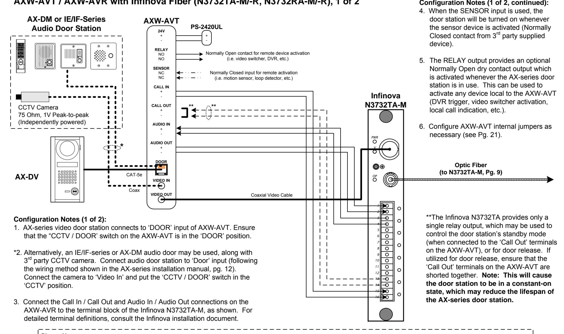
Please Note:
Only information pertaining to the connection and operation of the AXW-AVT / AXW-AVR and listed 3rd party devices interfacing with it are included here. Aiphone is not responsible for attempts to connect the AXW-AVT / AXW-AVR to untested 3rd party transmission hardware. Consult the installation manual for the 3rd party device being utilized for further information regarding physical mounting, base functionality, power requirements, etc. For the most up-to-date compatibility information, please consult http:// www.aiphone.com or contact Aiphone Technical Support.
Pg. 7 Pg. 8 For complete AX system installation, wiring, and programming information, please consult the AX Installation Manual (included on CD with AX Central Exchange Unit, or available at http://www.aiphone.com).
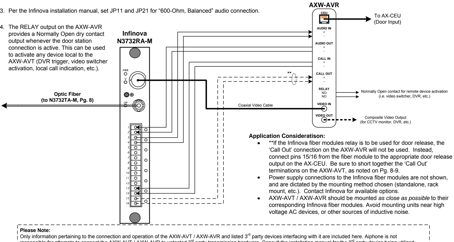
AXW-AVT / AXW-AVR with Infinova Fiber (N3732TA-M/-R, N3732RA-M/-R), 2 of 2
Configuration Notes (2 of 2):
- 1. Connect the AXW-AVR 'CEU' connection to an unused Door station input on the AX-CEU and ensure that the AX-CEU has been programmed to accept a video door station on that input (see Pg. 2).
- 2. Connect the Call In / Call Out and Audio In / Audio Out connections on the AXW-AVR to the terminal block of the Infinova N3732RA-M, as shown. For detailed terminal definitions, consult the Infinova installation document.
responsible for attempts to connect the AXW-AVT / AXW-AVR to untested 3rd party transmission hardware. Consult the installation manual for the 3rd party device being utilized for further information regarding physical mounting, base functionality, power requirements, etc. For the most up-to-date compatibility information, please consult http:// www.aiphone.com or contact Aiphone Technical Support.
Pg. 9 Pg. 10 For complete AX system installation, wiring, and programming information, please consult the AX Installation Manual (included on CD with AX Central Exchange Unit, or available at http://www.aiphone.com).
CONFIGURATION DIAGRAM: AXW-AVT / AXW-AVR with AFI (American Fibertek) Fiber (MT/MR-89A-AX), 1 of 2
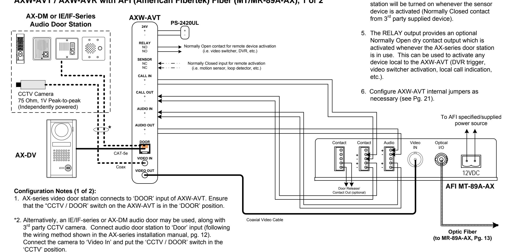
Connect the Call In / Call Out and Audio In / Audio Out connections on the AXW-AVT to the terminal block of the AFI MT-89A-AX, as shown. For detailed terminal definitions, consult the AFI MT-89A-AX installation sheet.
Please Note:
Only information pertaining to the connection and operation of the AXW-AVT / AXW-AVR and listed 3<sup>rd</sup> party devices interfacing with it are included here. Aiphone is not responsible for attempts to connect the AXW-AVT / AXW-AVR to untested 3<sup>rd</sup> party transmission hardware. Consult the installation manual for the 3<sup>rd</sup> party device being utilized for further information regarding physical mounting, base functionality, power requirements, etc. For the most up-to-date compatibility information, please consult http:// I www.aiphone.com or contact Aiphone Technical Support.
For complete AX system installation, wiring, and programming information, please consult the AX Installation Manual (included on CD with AX Central Exchange Unit, or available at http://www.aiphone.com).
Configuration Notes (1 of 2, continued): 4. When the SENSOR input is used, the door
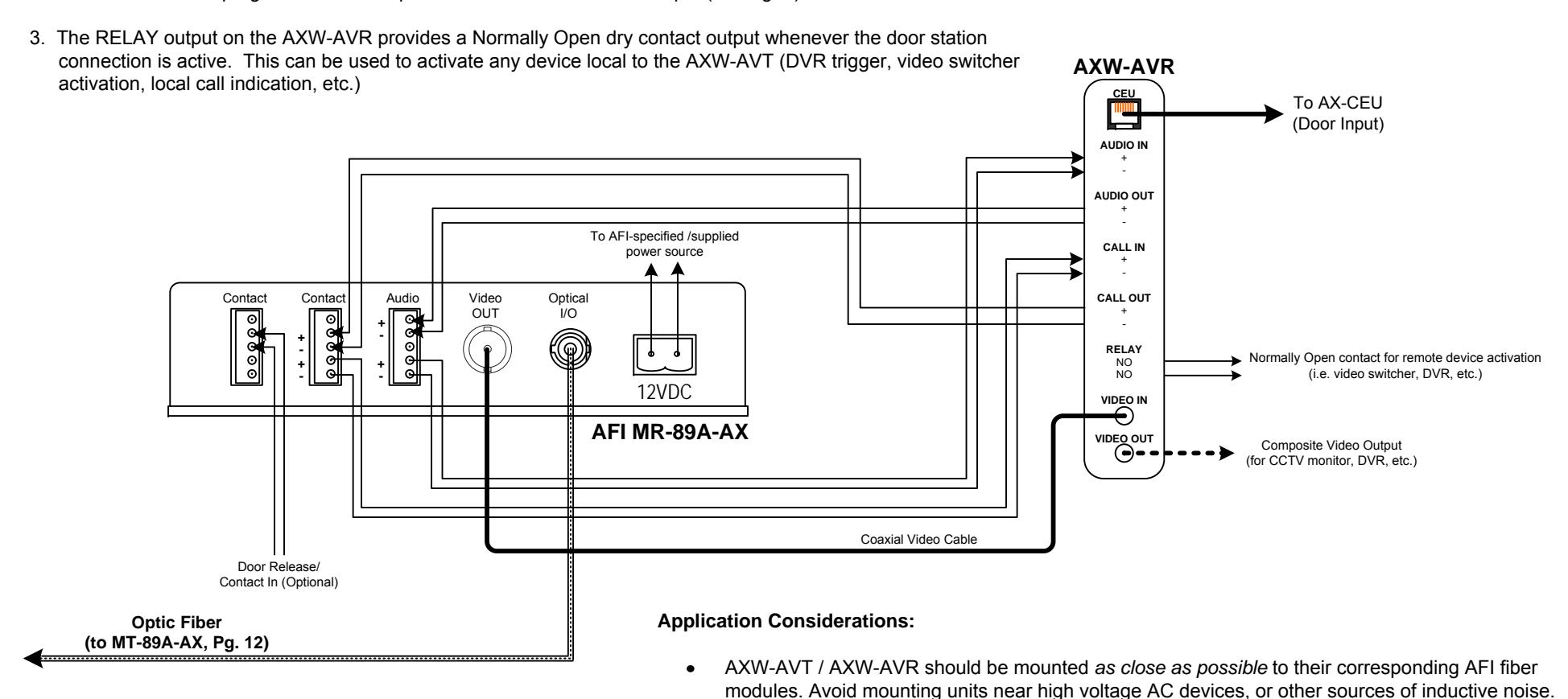
AXW-AVT / AXW-AVR with AFI (American Fibertek) Fiber (MT/MR-89A-AX), 2 of 2
Configuration Notes (2 of 2):
- 1. Connect the Call In / Call Out and Audio In / Audio Out connections on the AXW-AVR to the terminal block of the AFI MR-89A-AX, as shown. For detailed terminal definitions, consult the AFI MR-89A-AX installation sheet.
- 2. Connect the AXW-AVR 'CEU' connection to an unused Door station input on the AX-CEU and ensure that the AX-CEU has been programmed to accept a video door station on that input (see Pg. 2).
Please Note:
Only information pertaining to the connection and operation of the AXW-AVT / AXW-AVR and listed 3<sup>rd</sup> party devices interfacing with it are included here. Aiphone is not responsible for attempts to connect the AXW-AVT / AXW-AVR to untested 3<sup>rd</sup> party transmission hardware. Consult the installation manual for the 3<sup>rd</sup> party device being utilized for further information regarding physical mounting, base functionality, power requirements, etc. For the most up-to-date compatibility information, please consult http:// www.aiphone.com or contact Aiphone Technical Support.
For complete AX system installation, wiring, and programming information, please consult the AX Installation Manual (included on CD with AX Central Exchange Unit, or available at http://www.aiphone.com).
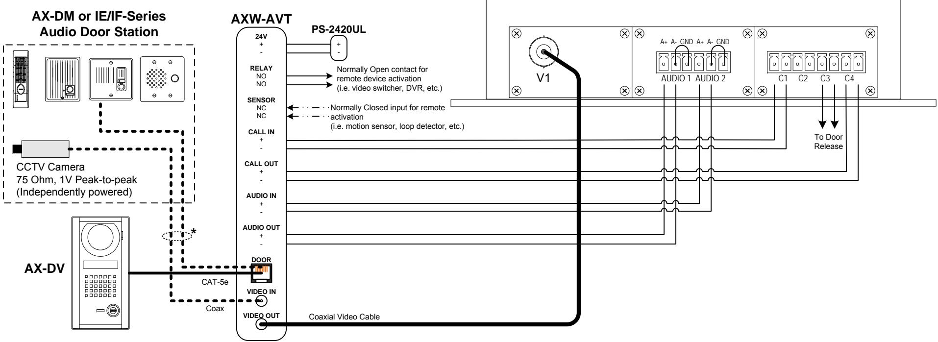
AXW-AVT / AXW-AVR with KBC Networks (FPVB1-AB1-IB2-ST, FPVB1-AB1-IB2-SR), 1 of 2
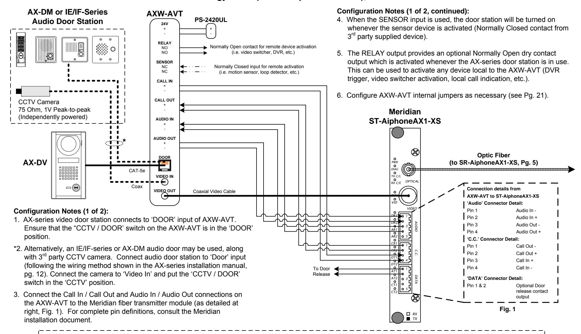
Configuration Notes (1 of 2):
- 1. AX-series video door station connects to 'DOOR' input of AXW-AVT. Ensure that the "CCTV / DOOR' switch on the AXW-AVT is in the 'DOOR' position.
- *2. Alternatively, an IE/IF-series or AX-DM audio door may be used, along with 3rd party CCTV camera. Connect audio door station to 'Door' input (following the wiring method shown in the AX-series installation manual, pg. 12). Connect the camera to 'Video In' and put the 'CCTV / DOOR' switch in the 'CCTV' position.
- 3. Connect the Call In / Call Out and Audio In / Audio Out connections on the AXW-AVT to the Meridian fiber transmitter module (as detailed at right, Fig. 1). For complete pin definitions, consult the Meridian installation document.
Configuration Notes (1 of 2, continued):
- 4. When the SENSOR input is used, the door station will be turned on whenever the sensor device is activated (Normally Closed contact from 3 rd party supplied device).
- 5. The RELAY output provides an optional Normally Open dry contact output which is activated whenever the AX-series door station is in use. This can be used to activate any device local to the AXW-AVT (DVR trigger, video switcher activation, local call indication, etc.).
- 6. Configure AXW-AVT internal jumpers as necessary (see Pg. 21).
KBC: FPVB1-AB1-IB2-ST
Please Note:
Only information pertaining to the connection and operation of the AXW-AVT / AXW-AVR and listed 3rd party devices interfacing with it are included here. Aiphone is not responsible for attempts to connect the AXW-AVT / AXW-AVR to untested 3rd party transmission hardware. Consult the installation manual for the 3rd party device being utilized for further information regarding physical mounting, base functionality, power requirements, etc. For the most up-to-date compatibility information, please consult http:// www.aiphone.com or contact Aiphone Technical Support.
Pg. 15 Pg. 16 For complete AX system installation, wiring, and programming information, please consult the AX Installation Manual (included on CD with AX Central Exchange Unit, or available at http://www.aiphone.com).
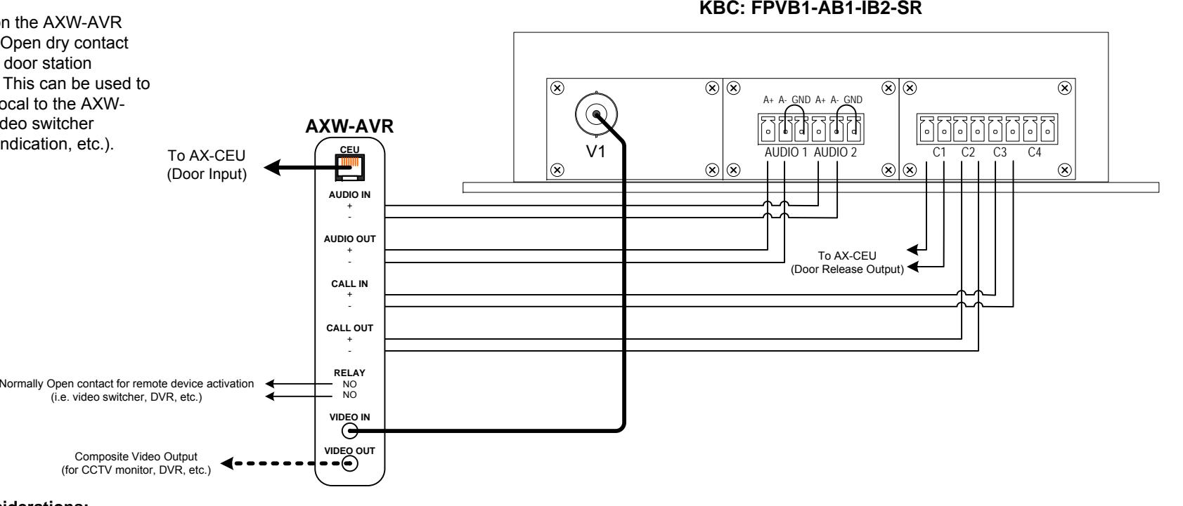
AXW-AVT / AXW-AVR with KBC Networks (FPVB1-AB1-IB2-ST, FPVB1-AB1-IB2-SR), 1 of 2
Configuration Notes (2 of 2):
- 1. Connect the Call In / Call Out and Audio In / Audio Out connections on the AXW-AVR to the terminal block of the AFI MR-1890, as shown. For detailed terminal definitions, consult the AFI MR-1890 installation sheet.
- 2. Connect the AXW-AVR 'CEU' connection to an unused Door station input on the AX-CEU and ensure that the AX-CEU has been programmed to accept a video door station on that input (see Pg. 2).
3. The RELAY output on the AXW-AVR provides a Normally Open dry contact output whenever the door station connection is active. This can be used to activate any device local to the AXW-AVT (DVR trigger, video switcher activation, local call indication, etc.).
Application Considerations:
- Power supply connections to the KBC fiber modules are not shown, and are dictated by the mounting method chosen (standalone, rack mount, etc.). Contact KBC for available options.
- AXW-AVT / AXW-AVR should be mounted as close as possible to their corresponding KBC fiber modules. Avoid mounting units near high voltage AC devices, or other sources of inductive noise.
Please Note:
Only information pertaining to the connection and operation of the AXW-AVT / AXW-AVR and listed 3rd party devices interfacing with it are included here. Aiphone is not responsible for attempts to connect the AXW-AVT / AXW-AVR to untested 3rd party transmission hardware. Consult the installation manual for the 3rd party device being utilized for further information regarding physical mounting, base functionality, power requirements, etc. For the most up-to-date compatibility information, please consult http:// www.aiphone.com or contact Aiphone Technical Support.
Pg. 17 Pg. 18 For complete AX system installation, wiring, and programming information, please consult the AX Installation Manual (included on CD with AX Central Exchange Unit, or available at http://www.aiphone.com).
AXW-AVT with Axis 243SA Video Server (Standalone Only)
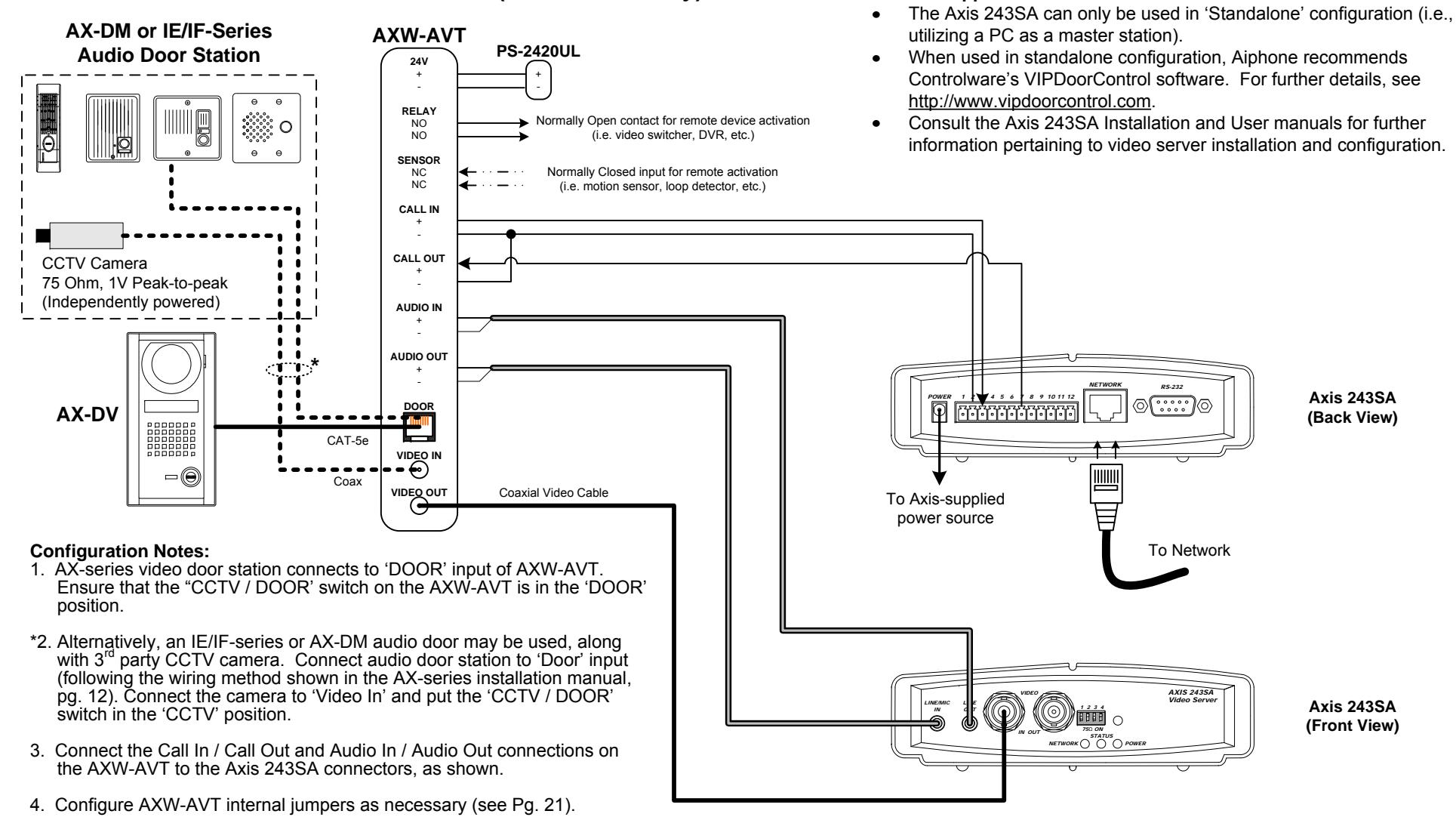
Axis 243SA Application Considerations:
Please Note:
Only information pertaining to the connection and operation of the AXW-AVT / AXW-AVR and listed 3<sup>rd</sup> party devices interfacing with it are included here. Aiphone is not responsible for attempts to connect the AXW-AVT / AXW-AVR to untested 3<sup>rd</sup> party transmission hardware. Consult the installation manual for the 3<sup>rd</sup> party device being utilized for further information regarding physical mounting, base functionality, power requirements, etc. For the most up-to-date compatibility information, please consult http://
For complete AX system installation, wiring, and programming information, please consult the AX Installation Manual (included on CD with AX Central Exchange Unit, or available at http://www.aiphone.com).
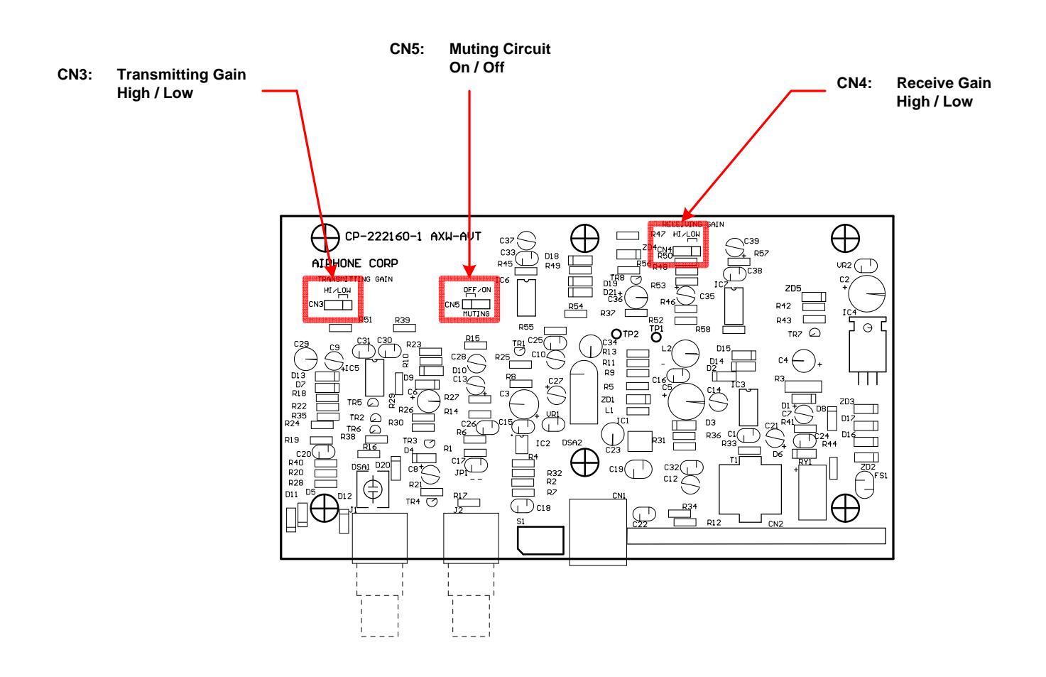
AXW-AVT Internal Jumper Settings:
The AXW-AVT has three internal jumper settings to control the functionality and conditioning of the audio circuitry. These should be adjusted as necessary, based on the selection of fiber / Ethernet equipment used. To access these jumpers, the chassis of the AXW-AVT will need to be opened. Adjusting these jumper settings will NOT invalidate the AXW-AVT's warranty.
Transmitting Gain (CN3): Controls the amount of amplification applied to the outgoing audio ('Audio Out')
connection of the AXW-AVT. A 'Low' setting provides no gain, whereas a 'Hi' setting applies approximately +10db of amplification. Default position is 'Low.'
Receive Gain (CN4): Controls the amount of amplification applied to the incoming audio ('Audio In')
connection of the AXW-AVT. A 'Low' setting provides no gain, whereas a 'Hi' setting applies approximately +10db of amplification. Default position is 'Low.'
Muting Circuit (CN5): The 'Muting Circuit' controls whether audio to/from the door station is
completely full-duplex, or limited to one direction or the other (semi-duplex). This adjustment is required in situations where latency may be present between audio transmission and reception (i.e., Ethernet). In such situations, the muting circuit should be set to 'On' to reduce audible echoing. In situations where latency is not an issue (i.e., fiber, direct connections, etc.), this should be left in
the default 'Off' position.
SPECIFICATIONS:
Power:
AXW-AVT 24V DC, 500mA (use Aiphone PS-2420UL)
AXW-AVR Supplied by AX CEU
Video Input & Output: Composite 1V Peak-to-Peak, NTSC
Video Connectors: BNC
Door input: RJ-45
Relay: Normally Open contact output; 30V DC, 1A
Sensor: Normally Closed contact input
Wire: CAT-5e, 24AWG UTP-4
Wiring distance:
AXW-AVT to Door, Max. 980' cumulative
AXW-AVR to CEU
AXW-AVT / -AVR to As close as possible; do not exceed 16'
3rd party devices
Dimensions:
AXW-AVT + AXW-AVR 1-5/8"H x 7"W x 4"D
FCC Class B Verification
NOTE: This equipment has been tested and found to comply with the limits for a Class B digital device , pursuant to Part 15 of the FCC Rules. These limits are designed to provide reasonable protection against harmful interference in a residential installation. This equipment generates, uses, and can radiate radio frequency energy and, if not installed and used in accordance with the instructions, may cause harmful interference to radio communications. However, there is no guarantee that interference will not occur in a particular installation. If this equipment does cause harmful interference to radio or television reception, which can be determined by turning the equipment off and on, the user is encouraged to try and correct the interference by one or more of the following measures:
- Reorient or locate the receiving antenna.
- Increase the separation between the equipment and receiver.
- Connect the equipment into an outlet on a circuit different from that to which the receiver is connected.
- Consult the dealer or an experienced radio/TV technician for help.
Note:
Only information pertaining to the connection and operation of the AXW-AVT, AXW-AVR and devices interfacing with it are included here. Aiphone is not responsible for attempts to connect the AXW-AVT / AXW-AVR to untested 3rd party transmission hardware. For the most up-to-date compatibility information, please consult http://www.aiphone.com or contact Aiphone Technical Support. For complete installation, wiring, and programming information regarding the AX system, please refer to the AX Installation Manual, which is included on the CD provided with the AX CEU, or available for download at http://www.aiphone.com.