Aiphone AI-MS900 Installation Instruction Manual
Open the original PDF document
View PDF

MASTER STATION
AI-MS900
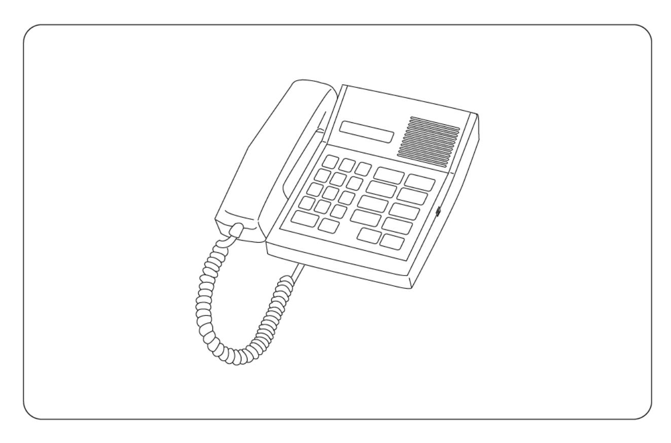
Be sure to leave system installations, adjustments, and data settings to the dealer from whom you have purchased.
Please follow the instructions in this manual to obtain the optimum results from this unit. We also recommend that you keep this manual handy for future reference.
TABLE OF CONTENTS
| 1. | SAFETY PRECAUTIONS | 3 |
|---|---|---|
| 2. | FCC REQUIREMENTS | 3 |
| 3. | INDUSTRY CANADA REQUIREMENTS | . 4 |
| 4. | INSTALLATION PRECAUTIONS | . 4 |
| 5. | GENERAL DESCRIPTION | . 5 |
| 6. | NOMENCLATURE AND FUNCTIONS | 5 |
| 7. | INSTALLATION | |
| 7.1. Mounting 7.1.1 Desk-top mounting | 6 | |
| 7.1.2 Wall mounting | ||
| 7.2. Connection and Adjustment | ||
| 7.2.1 External speaker connection | ||
| 7.2.2 Internal speaker volume and microphone sensitivity adjustment | / | |
| 8. | OPERATION | |
| 8.1. Calling a Substation | 8 | |
| 8.2. Calling a Master station (Telephone) | ||
| 8.3. Being Called | 9 | |
| 8.4. Conversation Method | 10 | |
| 8.5. Calling Party Display and Selective Response | ||
| 8.5.1 Calling party display | ||
| 8.5.2 Selective response | 12 | |
| 8.6. Auto Dialing | 12 | |
| 8.6.1 Auto dialing key call | ||
| 8.6.3 Auto dialing key registration erasure | ||
| 8.6.4 Auto dialing key registration confirmation | ||
| 8.7. Redial | ||
| 9. | SPECIFICATIONS | 16 |
| Accessories | 16 |
1. SAFETY PRECAUTIONS
- · Be sure to read the instructions in this section carefully before use.
- Make sure to observe the instructions in this manual as the conventions of safety symbols and messages regarded as very important precautions are included.
- We also recommend you keep this instruction manual handy for future reference.
⚠ WARNING
Indicates a potentially hazardous situation which, if mishandled, could result in death or serious personal injury.
- Do not expose the unit to rain or an environment where it may be splashed by water or other liquids, as doing so may result in fire or electric shock.
- Do not cut, kink, otherwise damage nor modify the connection cord. In addition, avoid using the cords in close proximity to heaters, and never place heavy objects on the cords, as doing so may result in fire or electric shock.
- Because the unit is an electrical device, users must not make wiring and installation. Leave the work to qualified personnel. Improper wiring or installation may cause electric shock.
- Do not disassemble nor modify the unit as doing so may result in fire or electric shock.
⚠ CAUTION
Indicates a potentially hazardous situation which, if mishandled, could result in moderate or minor personal injury, and/or property damage.
- Avoid installing the unit in humid or dusty locations, in locations exposed to the direct sunlight, near the heaters, or in locations generating sooty smoke or steam as doing otherwise may result in fire or electric shock.
- Check the chime volume with the handset placed on the hook as doing otherwise could impair hearing.
- Do not remove the unit from the wall nor change the unit locations. If the unit is reinstalled at improper location, it may fall or may hit persons causing injury.
2. FCC REQUIREMENTS
- (1) The Al-900 complies with FCC Rules, Part 68. On this equipment is a label which contains, among other information, the FCC Part 68 registration number.
- (2) The ringer equivalence number (REN) is used to determine the quality of devices which may be connected to the telephone line. Excessive RENs on the telephone line may result in the devices not ringing in response to an incoming call. In most, but not all areas, the sum of RENs should not exceed five (5.0). To be certain of the number of devices that may be connected to a line, as determined by the total RENs, contact the local telephone company.
Note: RENs are associated with loop-start and ground-start ports. It is not used for E&M and digital ports. The REN assigned to the AI-900 is 0.4. If requested, this information must be given to the telephone company.
(3) In the event of equipment malfunction, all repairs should be performed by AIPHONE CORPORATION or an authorized agent. It is the responsibility of users requiring service to report the need for service to AIPHONE CORPORATION or to one of our authorized agents. Service can be facilitated through our office at:
AIPHONE CORPORATION 1700-130th Ave., N.E. Bellevue, Washington 98009 Phone (425) 455-0510
The telephone company can ask you to disconnect the equipment from the network until the problem is corrected or until you are sure that the equipment is not malfunctioning.
- (4) If the AI-900 disrupts the telephone network, the telephone company can discontinue your service temporarily. If possible, the telephone company will notify you in advance. If advance notice is not practical, they will notify you as soon as possible. You are also informed of your right to file a complaint with the FCC.
- (5) The telephone company can make changes in its facilities, equipment, operations, or procedures that can affect the operation of your equipment. If they do, you should be notified in advance so you have an opportunity to maintain uninterrupted telephone service.
- (6) While the AI-900 is fully compliant with FCC rules and regulations, it is recommended that an alternating current (ac) surge arrestor of the form and capability suitable for the model purchased be installed in the ac outlet to which the AIPHONE CORPORATION products are connected. Consult with your distributor as to the surge protector requirements for your equipment.
- (7) The FCC rules require that the following Affidavit be completed by the installer and forwarded to the local exchange carrier, whenever digital terminal equipment without encoded analog content and billing protection is used to transmit digital signals containing encoded analog content, which are intended for eventual conversion into Voiceband analog signals and retransmitted on the network.
- (8) The AI-900 has been tested and comply with the limits for a class A digital device, pursuant to Part 15 of the FCC Rules. These limits are designed to provide reasonable protection against harmful interference when the equipment is operated in a commercial environment. This equipment generates, uses, and can radiate radio frequency energy and, if not installed and used in accordance with the instruction manual, can cause harmful interference to radio communications. Operation of this equipment in a residential area is likely to cause harmful interference, in which case the user will be required to correct the interference in the user's expense.
CHANGES OR MODIFICATIONS NOT EXPRESSLY APPROVED BY AIPHONE CORPORATION COULD VOID THE USER'S AUTHORITY TO OPERATE THE EQUIPMENT.
3. INDUSTRY CANADA REQUIREMENTS
(1) ''NOTICE: This equipment meets the applicable Industry Canada Terminal Equipment Technical Specifications.
This is confirmed by the registration number. The abbreviation, IC, before the registration number signifies that registration was performed based on a Declaration of Conformity indicating that Industry Canada technical specifications were met.
It does not imply that Industry Canada approved the equipment."
-
(2) ''NOTICE: The Ringer Equivalence Number (REN) for this terminal equipment is 0.4.
- The REN assigned to each terminal equipment provides an indication of the maximum number of terminals allowed to be connected to a telephone interface.
- The termination on an interface may consist of any combination of devices subject only to the requirement that the sum of the Ringer Equivalence Numbers of all the devices does not exceed five.''
- (3) "The abbreviation, IC, before the registration number signifies that registration was performed based on a Declaration of Conformity indicating that Industry Canada technical specifications were met. It does not imply that Industry Canada approved the equipment.
- (4) This Class A digital apparatus complies with Canadian ICES-003. Cet appareil numérique de la classe A est conforme à la norme NMB-003 du Canada.
4. INSTALLATION PRECAUTIONS
- The whole system will not operate without power supply.
- In areas where broadcasting stations are close by, the system operation may be affected by radio frequency interference.
- Keep the unit at least 1 m from TV or radio.
5. GENERAL DESCRIPTION
The AI-MS900 can make calls to or receive calls from the substation or the master station (telephone). It utilizes 2 pairs of twisted cables.
6. NOMENCLATURE AND FUNCTIONS
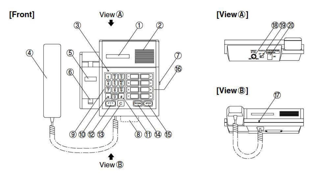
1. Display panel
Shows connection status and registered data.
2. Internal speaker
Sounds call tones and permits "handsfree" conversation.
3. In-use lamp
Lights when station is busy.
4. Handset
Lift the handset or press the [PTT] key to respond to a call.
5. Station number card
Write the station's number in this card.
6. Hook switch
Speaker volume selector switch [SP.VOL H/L] Adjusts the internal speaker's volume level.
8. Station number directory
9. Numeric dialing keys [0] – [9] Used for dialing
OSEG IOI GIA
10. [*] key
Used for registration and dialing operations of call paging functions or other special functions.
11. [#] key
Used for registration and dialing operations of special functions.
12. Press-to-talk [PTT] key
Used for speaking in press-to-talk conversation mode. Functions as a Response key to answer incoming calls.
13. Cancel [C] key
Terminates calls.
14. [REDIAL] key
Automatically redials the last dialed number. Also, functions as a station select key to cycle the display through waiting calls.
15. Transfer [XFER] key
Used to transfer calls. First press this key, then dial the station number to which calls are transferred.
16. Auto dialing keys [1] - [8]
Automatically dial the registered station number.
17. Internal microphone
Used in "handsfree" operation.
18. Handset speaker volume [HANDSET SP. VOL.]
Adjusts the handset speaker's volume level.
19. Registration ON/OFF switch [REGISTER ON/OFF]
Set this switch to ON when registering auto dialing information or other data into the station. Normally, set this switch to OFF.
20. Line connector [LINE]
Connects the line to the exchange.
7. INSTALLATION
7.1. Mounting
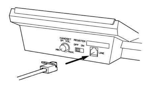
7.1.1. Desk-top mounting
Connect the supplied modular-plug cord.
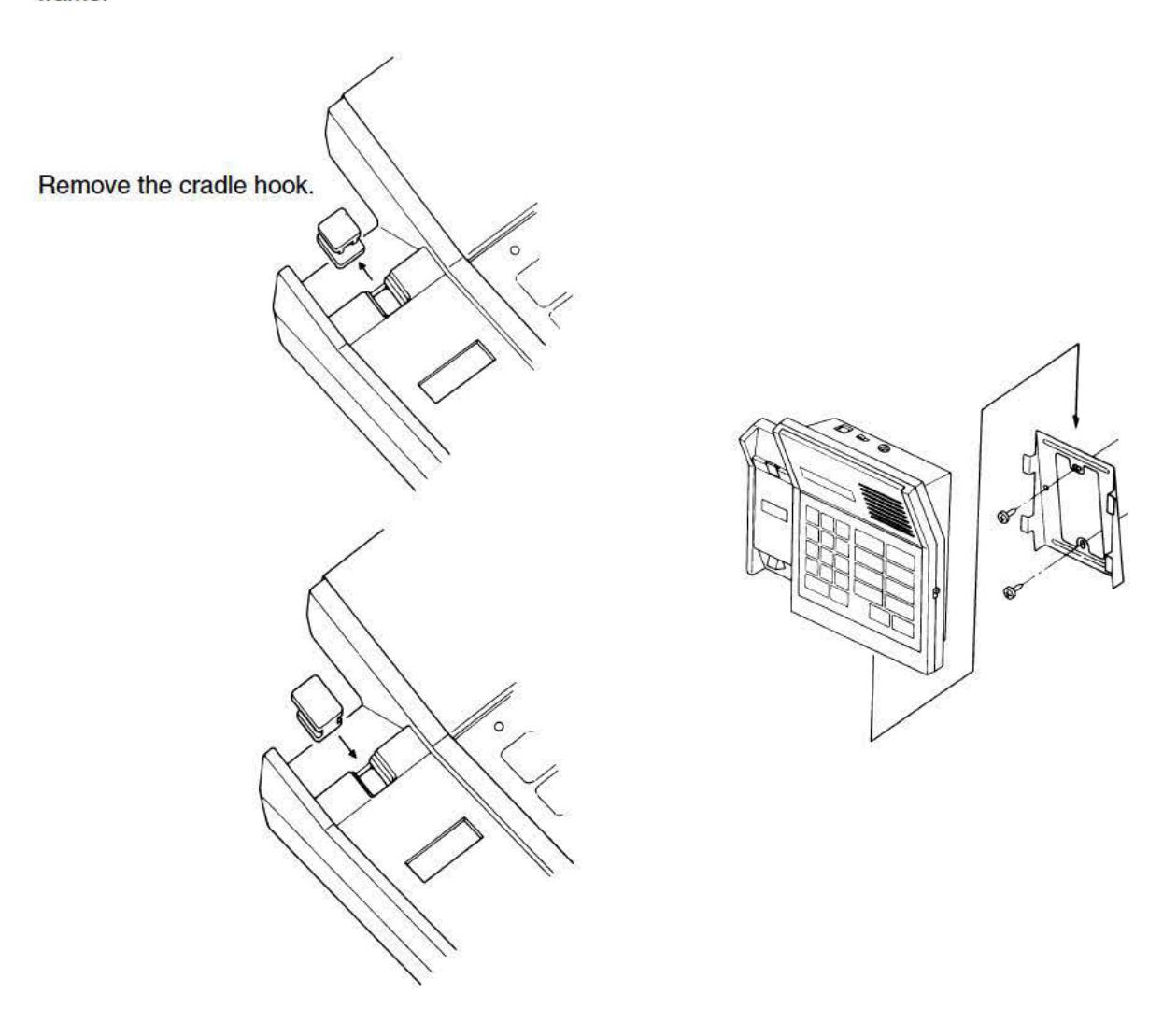
7.1.2. Wall mounting
Pull out, rotate, and reset the cradle hook, then mount the station on the wall using the supplied wall mounting frame.
7.2. Connection and Adjustment
7.2.1. External speaker connection
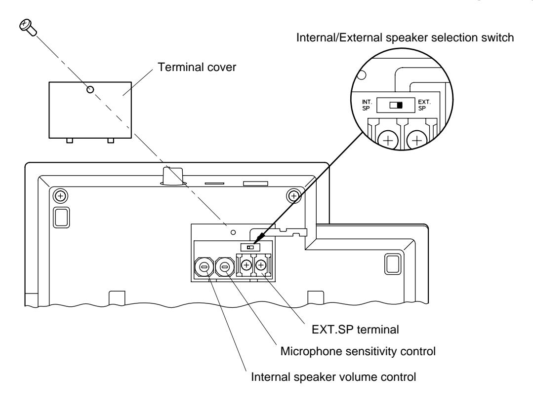
Follow the procedures below when connecting an external speaker (8Ω).
Step 1. Remove the AI-MS900's rear terminal cover and set the internal slide switch to the [EXT. SP] position.
Step 2. Connect the speaker cable to EXT.SP terminal.
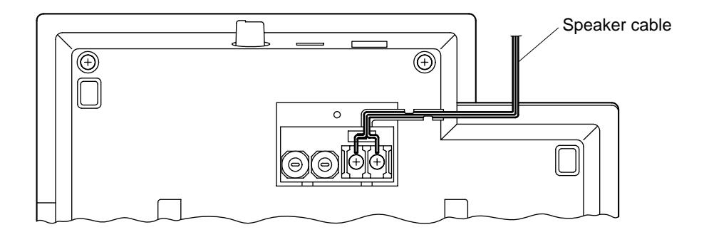
Step 3. Replace the removed terminal cover in place.
7.2.2. Internal speaker volume and microphone sensitivity adjustment
The AI-MS900's internal speaker volume and microphone sensitivity can be adjusted by means of their respective controls located under the terminal cover described above. Both controls are factory-preset to their maximum positions.
8. OPERATION
8.1. Calling a Substation
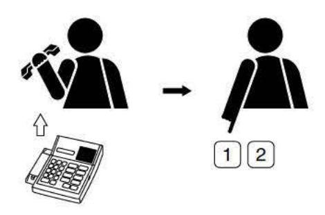
Step 1. Dial the desired substation number. (Dialing can be performed with the handset on-hook or off-hook.)
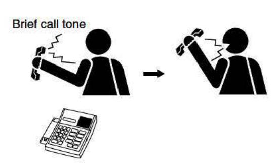
Step 2. Following a brief call tone, the master station is automatically connected to the substation. The master station's voice is heard at the substation while the master station operator is talking, and the substation's voice is only heard at the master station when the master station operator stops talking.
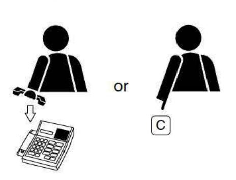
Step 3. To terminate the conversation, replace the handset or press the [C] key.
8.2. Calling a Master Station (Telephone)
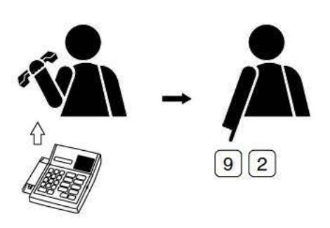
Step 1. Dial the desired station number. (Dialing can be performed with the handset on-hook or off-hook.)
Step 2. A trill call tone is heard at the calling station handset. (This tone will be heard from the station's internal speaker if dialed with the handset on-hook.)
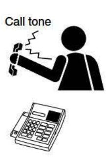
Step 3. The call tone stops and conversation can proceed when the called party answers.

Step 4. To terminate the conversation, replace the handset or press the [C] key.
8.3. Being Called
Step 1. A trill call tone is heard.
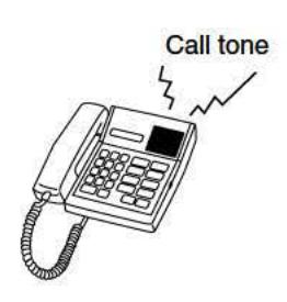
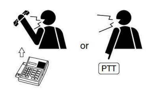
Step 2. Lifting the handset stops the call tone and permits conversation to proceed. (A response can also be made by pressing the [PTT] key for handsfree conversation.)
[Response with the [PTT] key]
- Simultaneous conversation is possible if the calling party is speaking with the master station handset lifted.
- (2) "Press-to-talk" alternate conversation is possible if the calling party is speaking with the master station handset on-hook.
Refer to "7.4. Conversation Method" on the next page.
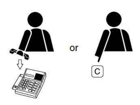
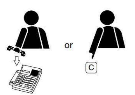
Step 3. To terminate the conversation, replace the handset or press the [C] key.
8.4. Conversation Method
There are three different conversation methods possible when the master station is used. The conversation method is determined by the other party's station type and handset use.
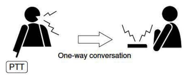
(1) Voice-operated switching conversation ("VOX" in the table below)
When both parties are talking coincidentally, the master station's (telephone's) party voice is transmitted to the substation. If the master station's party stops talking, the substation's party voice can be heard at the master station.
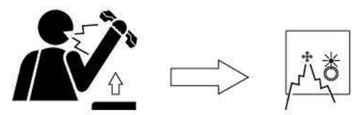
One-way conversation

One-way conversation
(2) "Press-to-talk" control conversation ("PTT" in the table below)
The [PTT] key is pressed to talk, and released to listen.
(3) Duplex conversation
Similar to the method of a standard telephone.

Simultaneous conversation
The following table shows the conversation modes for all of the various station combinations.
Quick reference of conversation methods
| Substation | Master Station | Talanhana | |||
|---|---|---|---|---|---|
| Off-hook | On-hook | Telephone | |||
| Substation |
(
|
VOX/PTT | PTT | VOX | |
| Master station | Handset off-hook | Duplex | Duplex | Duplex | |
| Handset on-hook | PTT | VOX | |||
| Telephone | Duplex | ||||
VOX: Voice-operated switching conversation PTT: "Press-to-talk" control conversation
Duplex: Simultaneous conversation
8.5. Calling Party Display and Selective Response
8.5.1. Calling party display
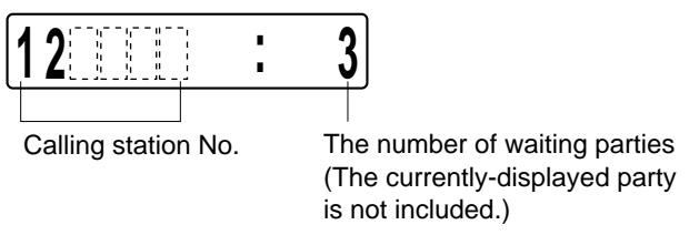
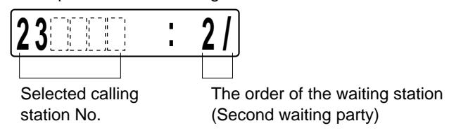
The master station can only display one of up to 64 calling stations by means of its 6-digit number or 8 character name. When the master station simultaneously receives calls from two or more stations, the station with the highest priority is displayed, and other waiting stations are displayed in order of priority as the [REDIAL] key is pressed. (Substation priorities are registered by system programming.)
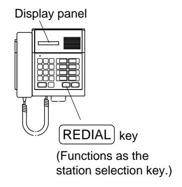
Example of calling station indication
Example of selected calling station indication
Note
For telephones, only the first calling station (telephone) number can be displayed. Soon after the conversation with the station is terminated, the call comes from the next waiting station in priority order and its station number is displayed. (This feature is available with "Caller ID" compatible telephones only.*)
* Depending on the type of telephone (and its display), even when the telephone simultaneously receives multiple calls, the number indication may not change, displaying the number different from that of an actual conversation partner.
[Calls are displayed in the following order of priority]
- 1. Emergency conference calls
- 2. Emergency substation calls
- 3. Incoming outside line calls
- 4. Normal substation calls
- 5. Master station or a telephone calls
8.5.2. Selective response
When multiple calls are simultaneously made to the master station, the master station can select and answer any desired calling party. (Note this function can only be performed by a dedicated master station and not a telephone.)
[Operation]
Step 1. Press the [REDIAL] key, and the station number or name of the second calling party will be displayed. (Subsequent depressions of the [REDIAL] key cycle the display through all waiting station numbers or names.)
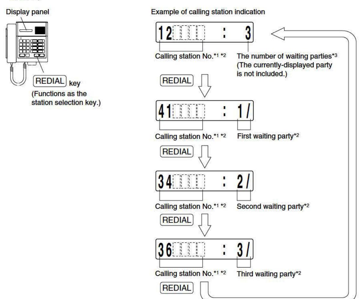
- *1 The name of the calling party may be displayed. Example: Store
- *2 Flashes when the call is made from a Emergency substation.
- *3 Flashes when the Emergency substation is included.
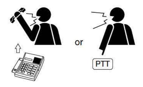
Step 2. Lift the handset when the desired station number (name) is displayed. The call tone then stops and conversation can begin. (The [PTT] key may also be pressed for handsfree response.)
8.6. Auto Dialing
8.6.1. Auto dialing key call
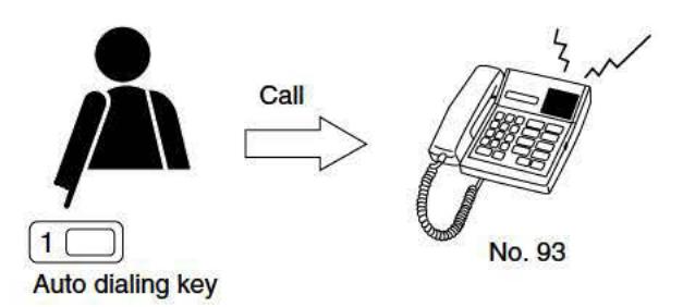
A one-touch press of an auto dialing key automatically dials the station number or functional number of dialing sequence to activate Paging, Call Forwarding, or other functions assigned to into that key. There are 8 auto dialing keys [1] - [8].
8.6.2. Auto dialing key registration
Step 1. Set the [REGISTER] switch on the master station's top panel to the ON position. The display panel will be placed in registration mode.
Step 2. Press the [PTT] key.
The following characters will be displayed.
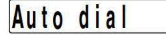
Step 3. Press the auto dialing key to register.
The selected key number (example: [2]) will be displayed.
2 : Example of auto dialing key [2]
If a station number or functional number has already been assigned to the auto dialing key, the assigned station number will also be displayed following the auto dialing key number (example: [2]).
2:90000 Example of auto dialing key [2] already assigned
Step 4. Press the [PTT] key.
2 : Example of auto dialing key [2]
The number, if previously assigned and displayed, will be erased.
Step 5. Press the new keys to register using the dialing keys [0] – [9] or function keys [ ], [#] or [REDIAL].
2 : 1 2 3456 Example of "123456" being entered
Notes
- If the [C] key is pressed before dialing a complete number, the contents before the [C] key was pressed are all erased.
- Mark "-" is displayed when the [REDIAL] key is pressed.
- The display shown below is an example of entering the functional number of paging.
2 : 8 0 #
Step 6. Press the [PTT] key after completing the entry of the registration number. Registration is then completed, as indicated by a confirmation tone.
2 : 1 2 3456 Example showing the registration completion of "123456"
Step 7. Shift the [REGISTER] switch back to the OFF position. The station will be placed in standby mode.
1 1 : 59am
8.6.3. Auto dialing key registration erasure
Step 1. Set the [REGISTER] switch on the master station's top panel to the ON position. The display panel will be placed in registration mode.
R e g –m o d e
Step 2. Press the [PTT] key.
The following characters will be displayed.
Au t o d i a l
Step 3. Press the registered auto dialing key to delete. The selected key number (example: [2]) will be displayed together with the registered number.
2 : 1 2 3456 Example showing "123456" has been registered
Step 4. Press the [PTT] key.
The registered number displayed after the auto dialing key [2] will be erased.
2 : Example of auto dialing key [2]
Step 5. Press the [PTT] key again.
The erasure is then completed, as indicated by a confirmation tone.
2 : Example of auto dialing key [2]
Step 6. Shift the [REGISTER] switch back to the OFF position. The station will be placed in standby mode.
1 1 : 59am
8.6.4. Auto dialing key registration confirmation
Step 1. Set the [REGISTER] switch on the master station's top panel to the ON position. The display panel will be placed in registration mode.
R e g –m o d e
Step 2. Press the [PTT] key.
The following characters will be displayed.
Au t o d i a l
Step 3. Press the registered Auto dialing key to be confirmed. The selected key number (example: [2]) will be displayed together with the registered number.
2 : 1 2 3456 Example showing auto dialing key [2] registration display
If the registered number being displayed exceeds the available display screen, pressing the [#] key advances the display to the next digit screen, and pressing the [ ] key returns the display to the previous digit screen.
Step 4. Shift the [REGISTER] switch back to the OFF position. The station will be placed in standby mode.
1 1 : 59am
8.7. Redial
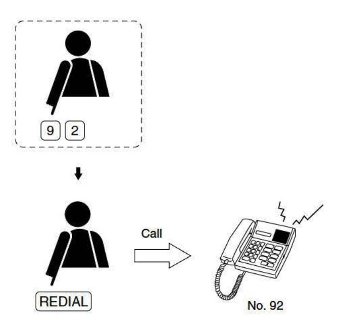
By one-touch pressing the master station's [REDIAL] key, the last dialed number will be dialed again.
9. SPECIFICATIONS
| Power Source | 24 V DC (supplied from the main frame) | |||
|---|---|---|---|---|
| Current Consumption | 60 mA | |||
| Talk System | Duplex or semi-duplex conversation | |||
| Talk Frequency | 300 – 3,400 Hz | |||
| Handset Microphone/Speaker | Dynamic type, 150 Ω | |||
| Handsfree Microphone | Electret condenser microphone | |||
| Station Speaker | Dynamic type, 8 Ω, ø57 mm, 0.6 W | |||
| Key Pad | Membrane switch | |||
| Display | 12 digits LCD | |||
| Auto dialing Key | 8 keys | |||
| Station Speaker Volume Control | 2-step selection slide switch | |||
| Handset Speaker Volume Control | Volume, 0 to +12 dB | |||
| Installation Method | Desk-/wall-mountable | |||
| Wiring | Twisted pair cables/2-pair | |||
| Connection Terminal | Line output: 6-position 4-contact modular jack | |||
| External speaker output: 2-pin screw terminal (8 Ω, 0.6 W) | ||||
| Operating Temperature | 0 – 40°C | |||
| Finish | ABS resin, pale white | |||
| Dimensions | 216 (w) x 74.5 (h) x 213 (d) mm | |||
| Weight | 940 g | |||
Note: The design and specifications are subject to change without notice for improvement.
Accessories
| Wall mounting bracket | 1 |
|---|---|
| Connection cord (3 m) | 1 |
| Wood screw |