Aiphone AI-900 Voice Security System Installation Manual
Open the original PDF document
View PDF

INSTALLATION MANUAL
VOICE SECURITY SYSTEM
AI-900
Be sure to leave system installations, adjustments, and data settings to the dealer from whom you have purchased.
Please follow the instructions in this manual to obtain the optimum results from this unit. We also recommend that you keep this manual handy for future reference.
TABLE OF CONTENTS
| 1. | SAFETY PRECAUTIONS | 4 |
|---|---|---|
| 2. | FCC REQUIREMENTS | 6 |
| 3. | INDUSTRIAL CANADA REQUIREMENTS | 7 |
| 4. | GENERAL DESCRIPTION | 8 |
| 5. | FEATURES | 8 |
| 6. | INSTALLATION PRECAUTIONS | 8 |
| 7. | SYSTEM CONFIGURATION AND EQUIPMENT FUNCTIONS | _ |
| 7.1. System Configuration | ||
| 8. | AI-900MF MAIN FRAME NOMENCLATURE AND FUNCTIONS | 11 |
| 9. | INSTALLATION AND CONNECTION PROCEDURES | 12 |
| 10. | EQUIPMENT INSTALLATION | |
| 10.1. AI-900MF Main Frame | ||
| 10.1. Al-900ivii iviaii i laine | ||
| 10.1.1. Rack mounting | 13 | |
| 10.1.1. Rack mounting | ||
| 10.1.1. Rack mounting | 14 | |
| 10.1.1. Rack mounting |
14
15 |
|
| 10.1.1. Rack mounting |
14
15 16 |
|
| 10.1.1. Rack mounting 10.1.2. Wall mounting 10.2. Al-PU200 Power Transformer unit 10.2.1. Rack mounting 10.2.2. Wall mounting 10.3. Al-RS150, Al-RS160, Al-RS170 and Al-RS180 Substations 10.4. Master Station |
14
15 16 17 |
|
| 10.1.1. Rack mounting 10.1.2. Wall mounting 10.2. AI-PU200 Power Transformer unit 10.2.1. Rack mounting 10.2.2. Wall mounting 10.3. AI-RS150, AI-RS160, AI-RS170 and AI-RS180 Substations 10.4. Master Station 10.4.1. Desk-top mounting |
14
15 16 17 |
|
| 10.1.1. Rack mounting 10.1.2. Wall mounting 10.2. Al-PU200 Power Transformer unit 10.2.1. Rack mounting 10.2.2. Wall mounting 10.3. Al-RS150, Al-RS160, Al-RS170 and Al-RS180 Substations 10.4. Master Station |
14
15 16 17 |
|
| 11. | 10.1.1. Rack mounting 10.1.2. Wall mounting 10.2. Al-PU200 Power Transformer unit 10.2.1. Rack mounting 10.2.2. Wall mounting 10.3. Al-RS150, Al-RS160, Al-RS170 and Al-RS180 Substations 10.4. Master Station 10.4.1. Desk-top mounting 10.4.2. Wall mounting |
14
15 16 17 18 |
| 11. | 10.1.1. Rack mounting 10.1.2. Wall mounting 10.2. AI-PU200 Power Transformer unit 10.2.1. Rack mounting 10.2.2. Wall mounting 10.3. AI-RS150, AI-RS160, AI-RS170 and AI-RS180 Substations 10.4. Master Station 10.4.1. Desk-top mounting 10.4.2. Wall mounting |
14
15 16 17 18 18 |
| 12. | WIRING | |
|---|---|---|
| 12.1. Wiring from the Station or Outside Line 21 | ||
| 12.2. Supplied Connector Connection 22 | ||
| 12.3. AI-900MS Master Station Interface Card Connection | ||
| 12.3.1. Master Station and AI-900MS connection 23 | ||
| 12.3.2. External recording device and AI-900MS connection 25 | ||
| 12.4. AI-MS900 Master Station Connection and Adjustment | ||
| 12.4.1. External speaker connection 26 | ||
| 12.4.2. Speaker volume and microphone sensitivity adjustment 26 | ||
| 12.5. AI-900AL Telephone Interface Card Connection | ||
| 12.5.1. Telephone and AI-900AL connection 27 | ||
| 12.5.2. External recording device and AI-900AL connection 29 | ||
| 12.6. AI-900RS Substation Interface Card Connection | ||
| 12.6.1. Substation and AI-900RS connection 30 | ||
| 12.6.2. External amplifier and AI-900RS connection 31 | ||
| 12.7. AI-900CO Outside Line Interface Card Connection | ||
| 12.7.1. Outside line and AI-900CO connection 32 | ||
| 12.7.2. External recording device and AI-900CO connection 33 | ||
| 12.8. AI-900AF Audio Function Card Connection | ||
| 12.8.1. Amplifier and AI-900AF connection 34 | ||
| 12.8.2. External sound source and AI-900AF connection 35 | ||
| 12.9. AI-900TI Tie-Line Interface Card Exchange Interconnection 36 | ||
| 12.10. AI-900MF Main Frame and AI-PU200 Power Transformer Connection 39 | ||
| 13. | MAIN FRAME AND PC CONNECTION | |
| 13.1. Programming PC Connection | ||
| 13.1.1. Direct connection by means of RS-232C 40 | ||
| 13.1.2. Connection via modem 41 | ||
| 13.2. Operation Log PC Connection | ||
| 13.2.1. Direct connection by means of RS-232C 42 | ||
| 13.2.2. Connection via modem 43 | ||
| 13.3. System Programming 43 | ||
| 14. | SPEECH AND FUNCTION TESTS | |
| 14.1. Speech Test 44 | ||
| 14.2. Function Test 44 | ||
| 15. |
SPECIFICATIONS
45 |
|
| Accessories 45 |
1. SAFETY PRECAUTIONS
- · Be sure to read the instructions in this section carefully before use.
- Make sure to observe the instructions in this manual as the conventions of safety symbols and messages regarded as very important precautions are included.
- We also recommend you keep this instruction manual handy for future reference.
Safety Symbol and Message Conventions
Safety symbols and messages described below are used in this manual to prevent bodily injury and property damage which could result from mishandling. Before operating your product, read this manual first and understand the safety symbols and messages so you are thoroughly aware of the potential safety hazards.
MARNING
Indicates a potentially hazardous situation which, if mishandled, could result in death or serious personal injury.

Indicates a potentially hazardous situation which, if mishandled, could result in moderate or minor personal injury, and/or property damage.
MARNING
When Installing the Unit
[Applicable to the exchange and the station]
- Do not expose the unit to rain or an environment where it may be splashed by water or other liquids, as doing so may result in fire or electric shock.
- Do not cut, kink, otherwise damage nor modify the power supply cord and connection cord. In addition, avoid using the cords in close proximity to heaters, and never place heavy objects -- including the unit itself -- on the cords, as doing so may result in fire or electric shock.
[Applicable to the exchange]
- Use the unit only with the voltage specified on the unit. Using a voltage higher than that which is specified may result in fire or electric shock.
- Be sure to ground to the safety ground (earth) terminal to avoid electric shock. Never ground to a gas pipe as a catastrophic disaster may result.
- Owing to the unit's size and weight, be sure that at least two persons are available to install the unit. Failure to do so could result in personal injury.
- Because the Al-900 is an electrical device, users must not make wiring and installation. Leave the work to qualified personnel. Improper wiring or installation may cause electric shock.
Never perform wiring nor installation work while power is turned on as doing so may cause fire or damage to the unit.
(When mounted on a wall)
Avoid installing the Al-MS900 Master Station on a wall in locations where it may hit persons or it may fall. Failure to do so may result in injury.
(When mounted on a wall)
Install the unit only in a location that can structurally support the weight of the unit and the mounting bracket. Doing otherwise may result in the unit falling down and causing personal injury and/or property damage.
When the Unit is in Use
[Applicable to the exchange]
-
Should the following irregularity be found during use, immediately switch off the power, disconnect the power supply plug from the AC outlet and contact your nearest AIPHONE dealer. Make no further attempt to operate the unit in this condition as this may cause fire or electric shock.
- If you detect smoke or a strange smell coming from the unit.
- · If water or any metallic object gets into the unit
- To prevent a fire or electric shock, never open nor remove the unit case as there are high voltage components inside the unit. Refer all servicing to your nearest AIPHONE dealer.
- Do not place cups, bowls, or other containers of liquid or metallic objects on top of the unit. If they accidentally spill into the unit, this may cause a fire or electric shock.
- Do not touch the power cord during thunder and lightning, as this may result in electric shock.
- Do not connect any power supply other than specified to the AI-900MF's DC power input terminals.
Doing so could result in fire or damage to the unit.
⚠ CAUTION
When Installing the Unit
[Applicable to the exchange and the station]
Avoid installing the unit in humid or dusty locations, in locations exposed to the direct sunlight, near the heaters, or in locations generating sooty smoke or steam as doing otherwise may result in fire or electric shock.
[Applicable to the exchange]
Do not block the ventilation slots in the unit's cover. Doing so may cause heat to build up inside the unit and result in fire.
When the Unit is in Use
[Applicable to the exchange]
- Do not place heavy objects on the unit as this may cause it to fall or break which may result in personal injury and/or property damage. In addition, the object itself may fall off and cause injury and/or damage.
- Contact your AIPHONE dealer as to the cleaning. If dust is allowed to accumulate in the unit over a long period of time, a fire or damage to the unit may result.
2. FCC REQUIREMENTS
- (1) The AI-900 complies with FCC Rules, Part 68. On this equipment is a label which contains, among other information, the FCC Part 68 registration number.
- (2) The ringer equivalence number (REN) is used to determine the quality of devices which may be connected to the telephone line. Excessive RENs on the telephone line may result in the devices not ringing in response to an incoming call. In most, but not all areas, the sum of RENs should not exceed five (5.0). To be certain of the number of devices that may be connected to a line, as determined by the total RENs, contact the local telephone company.
Note: RENs are associated with loop-start and ground-start ports. It is not used for E&M and digital ports. The REN assigned to the AI-900 is 0.4. If requested, this information must be given to the telephone company.
(3) In the event of equipment malfunction, all repairs should be performed by AIPHONE CORPORATION or an authorized agent. It is the responsibility of users requiring service to report the need for service to AIPHONE CORPORATION or to one of our authorized agents. Service can be facilitated through our office at:
AIPHONE CORPORATION 1700-130th Ave., N.E. Bellevue, Washington 98009 Phone (425) 455-0510
The telephone company can ask you to disconnect the equipment from the network until the problem is corrected or until you are sure that the equipment is not malfunctioning.
- (4) If the AI-900 disrupts the telephone network, the telephone company can discontinue your service temporarily. If possible, the telephone company will notify you in advance. If advance notice is not practical, they will notify you as soon as possible. You are also informed of your right to file a complaint with the FCC.
- (5) The telephone company can make changes in its facilities, equipment, operations, or procedures that can affect the operation of your equipment. If they do, you should be notified in advance so you have an opportunity to maintain uninterrupted telephone service.
- (6) While the AI-900 is fully compliant with FCC rules and regulations, it is recommended that an alternating current (ac) surge arrestor of the form and capability suitable for the model purchased be installed in the ac outlet to which the AIPHONE CORPORATION products are connected. Consult with your distributor as to the surge protector requirements for your equipment.
- (7) The FCC rules require that the following Affidavit be completed by the installer and forwarded to the local exchange carrier, whenever digital terminal equipment without encoded analog content and billing protection is used to transmit digital signals containing encoded analog content, which are intended for eventual conversion into Voiceband analog signals and retransmitted on the network.
- (8) The AI-900 has been tested and comply with the limits for a class A digital device, pursuant to Part 15 of the FCC Rules. These limits are designed to provide reasonable protection against harmful interference when the equipment is operated in a commercial environment. This equipment generates, uses, and can radiate radio frequency energy and, if not installed and used in accordance with the instruction manual, can cause harmful interference to radio communications. Operation of this equipment in a residential area is likely to cause harmful interference, in which case the user will be required to correct the interference in the user's expense.
CHANGES OR MODIFICATIONS NOT EXPRESSLY APPROVED BY AIPHONE CORPORATION COULD VOID THE USER'S AUTHORITY TO OPERATE THE EQUIPMENT.
3. INDUSTRY CANADA REQUIREMENTS
(1) ''NOTICE: This equipment meets the applicable Industry Canada Terminal Equipment Technical Specifications.
This is confirmed by the registration number. The abbreviation, IC, before the registration number signifies that registration was performed based on a Declaration of Conformity indicating that Industry Canada technical specifications were met.
It does not imply that Industry Canada approved the equipment."
-
(2) ''NOTICE: The Ringer Equivalence Number (REN) for this terminal equipment is 0.4. The REN assigned to each terminal equipment provides an indication of the maximum number of terminals allowed to be connected to a telephone interface.
- The termination on an interface may consist of any combination of devices subject only to the requirement that the sum of the Ringer Equivalence Numbers of all the devices does not exceed five.''
- (3) "The abbreviation, IC, before the registration number signifies that registration was performed based on a Declaration of Conformity indicating that Industry Canada technical specifications were met. It does not imply that Industry Canada approved the equipment.
- (4) This Class A digital apparatus complies with Canadian ICES-003. Cet appareil numérique de la classe A est conforme à la norme NMB-003 du Canada.
4. GENERAL DESCRIPTION
The AI-900 Security System is a voice communication system that permits calls to be quickly and easily made - even in emergency situations - with the touch of single button. The system can record conversations, and features external equipment sync output and operation log output. These features combine to make the AI-900 an ideal system for voice security applications.
5. FEATURES
- Modular construction facilitates installation, maintenance, and system expansion.
- Rack- or wall-mountable exchange.
- Up to 4 master stations (or commercial telephone sets) and 64 substations can be connected per exchange.
- Up to 2 outside telephone (C/O) lines can be connected per exchange.
- Station paging (by means of the substation speaker) and external paging functions.
- External sound source distribution capability.
- Up to 19 paging zones can be established.
- Emergency Paging function.
- By connecting an external recording device, the conversations at the master station (or telephone set) and at the outside line telephone can be recorded.
- Exchange operating log can be transmitted to a PC.
- Tie-line possible for up to 16 exchanges.
- 24 V DC input for connection of backup power supply.
- Manual/Automatic Call Forwarding, Conference, Scan Monitor functions.
6. INSTALLATION PRECAUTIONS
- To prevent the unit's failure, be sure to switch off its power when inserting or removing the card.
- When mounting each card, fully insert it into the Main Frame. After all cards are mounted, secure them with the card fixing bracket.
- When the unit gets dirty with dust or oil, wipe down with a soft, dry cloth. Never use a chemically-treated cleaning cloth or volatile liquids, such as benzine and thinner, because the unit's plastic parts may be deformed or its finish discolored.
- All units except the AI-RS170 and AI-RS180 Substations are designed exclusively for indoor use. Do not install them outdoors.
- The whole system will not operate without power supply.
- In areas where broadcasting stations are close by, the system operation may be affected by radio frequency interference.
- Keep DC wiring at least 30 cm away from AC wiring. Otherwise, the system may malfunction.
7. SYSTEM CONFIGURATION AND EQUIPMENT FUNCTIONS
7.1. System Configuration
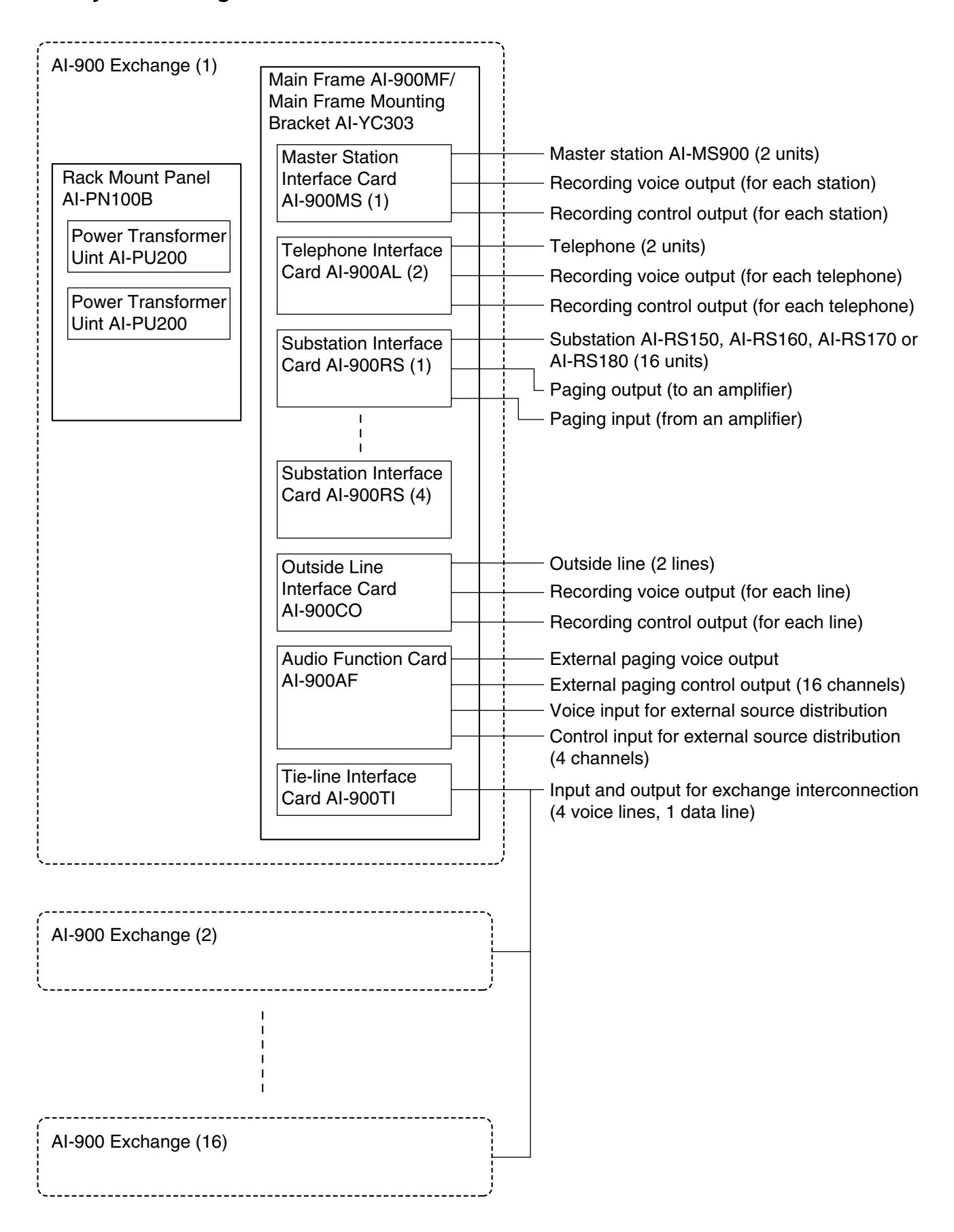
7.2. Equipment Functions
• AI-900MF Main Frame
The AI-900MF accommodates the following cards: Up to 2 AI-900MS or AI-900AL Cards (both cards may be mixed), up to 4 AI-900RS Cards, 1 AI-900CO Card, 1 AI-900AF Card, and 1 AI-900TI Card.
The Main Frame has 2 RS-232C ports; one for programming and the other for operation log output.
• AI-900MS Master Station Interface Card
The AI-900MS is used for master station connection. Up to 2 master stations can be connected per card, and an external recording device can be connected to each line.
• AI-900AL Telephone Interface Card
The AI-900AL is used for connecting telephone sets (in compliance with the FCC Regulation Part 68). Up to 2 telephones can be connected per card, and an external recording device can be connected to each line.
• AI-900RS Substation Interface Card
The AI-900RS is used for substation connection. Up to 16 substations can be connected per card. The Substation Interface Card has 2 speech links, one of which also functions as a paging link with the paging input/output connected to an external amplifier.
• AI-900CO Outside Line Interface Card
The AI-900CO is used for outside line connection. Up to 2 outside lines can be connected per card, and an external recording device can be connected to each line.
• AI-900AF Audio Function Card
The AI-900AF enables Conference, External Amplifier Paging, and External Source Distribution functions. The Audio Function Card has 1 conference link (maximum 4 stations), 1 voice output and 16 control outputs for external amplifier paging, and 1 voice input and 4 control inputs for external source distribution.
• AI-900TI Tie-Line Interface Card
The AI-900TI is used to interconnect multiple exchanges. The Tie-Line Interface Card can connect up to 4 links made up by 1 pair of data lines and 2 pairs of voice lines.
• AI-PU200 Power Transformer Unit
The wall-mountable AI-PU200 has 2 20V/2.5A AC outputs. One AI-PU200 unit is required when up to 2 AI-900RS Cards are installed, and 2 AI-PU200 units are required when 3 or more AI-900RS Cards are installed.
• AI-YC303 Main Frame Wall Mounting Bracket
The AI-YC303 is used when mounting the main frame on the wall.
• AI-PN100B Rack Mount Panel
The AI-PN100B provides side-by-side rack mounting capability for up to 2 AI-PU200 transformer units.
• AI-MS900 Master Station
The AI-MS900 can make calls to or receive calls from the substation. It utilizes 2 pairs of twisted cables.
• AI-RS150 Substation (Indoor Type)
The AI-RS150 can call and converse with the registered master stations. It utilizes a single-pair shielded cable.
• AI-RS160 Substation (Indoor Vandal-Resistant Type)
The AI-RS160 can call and converse with the registered master stations. It utilizes a single-pair shielded cable.
• AI-RS170 Substation (Outdoor Vandal-Resistant Type)
The AI-RS170 can call and make converse with the registered master stations. It utilizes a single-pair shielded cable.
• AI-RS180 Substation (for Emergency Use)
The AI-RS180 can call and converse with the registered master stations. It has a indicator lamp and a control output channel, and utilizes a single-pair shielded cable.
8. AI-900MF MAIN FRAME NOMENCLATURE AND FUNCTIONS
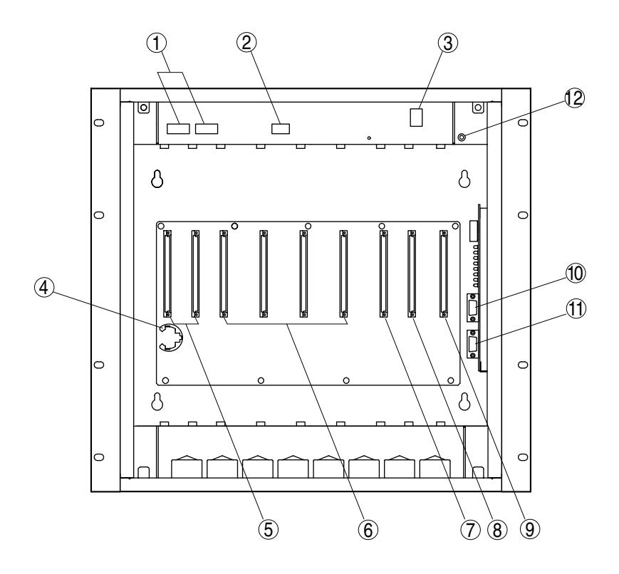
1. AC Input Connectors
Connect to the AC output terminal of the AI-PU200 power transformer unit. (See p. 39.)
2. 24 V DC Input Connector
Connects to a battery (24 V DC). (See p. 39.)
3. Power Switch
Power is switched on (I) and off (O) with each depression of this switch.
4. Backup Battery Socket
Insert the CR2032 data backup battery into this socket. (See p. 19.)
5. AI-900MS/AI-900AL Installation Slot [MS/AL 1-2] A maximum of 2 AI-900MS or AI-900AL cards can be installed. (See p. 24 and 29.)
6. AI-900RS Installation Slot [RS 1-4]
A maximum of 4 AI-900RS cards can be installed. (See p. 30.)
7.AI-900CO Installation Slot [CO]
One AI-900CO card can be installed. (See p. 32.)
8. AI-900AF Installation Slot [AF]
One AI-900AF card can be installed. (See p. 34.)
9. AI-900TI Installation Slot [TI]
One AI-900TI card can be installed. (See p. 36.)
10. Programming PC Connector [RS-232C]
Connects to the programming PC either directly or via modem. (See p. 40.)
11. Operation Log PC Connector [RS-232C]
Connects to the operation log PC either directly or via modem. (See p. 42.)
12. Power Indicator
Lights when the power switch is set to ON.
9. INSTALLATION AND CONNECTION PROCEDURES
|
(2) Equipment Installation
Installing the AI-900MF Main Frame in an Equipment Rack or on a Wall Installing the AI-PU200 Power Transformer in an Equipment Rack or on a Wall Installing the Substation Installing the Master Station (3) Installing a Card in the AI-900MF Main Frame Installing the Data Backup Battery (See p. 19.) Installing and Connecting Each Card (4) Connecting the Station/Outside Line to Each Exchange Card • AI-MS900 Master Station vs. AI-900MS Card (See p. 23.) • External Recording Device vs. AI-900MS Card • Telephone vs. AI-900AL Card • External Recording Device vs. AI-900AL Card • Substation vs. AI-900RS Card • External Amplifier vs. AI-900RS Card (See p. 31.) • Outside Line vs. AI-900CO Card (See p. 32.) • External Recording Device vs. AI-900CO Card • External Amplifier vs. AI-900AF Card • External Recording Device vs. AI-900AF Card (See p. 35.) AI-900MF Main Frame vs. AI-PU200 Power Transformer (See p. 39.) (5) Tie-Line Connection (between Exchanges) AI-900TI vs. AI-900TI (See p. 36.) Connection to a Programming PC Connection to an Operation Log PC Power-ON System Programming (See the "AI-900 SETUP SOFTWARE MANUAL.") Master Station Microphone Sensitivity/Speaker Volume Adjustment Telephone Volume Adjustment (AI-900AL Card) (8) Speech and Function Tests Speech Test (See p. 44.) Function Test (See p. 44.) |
(1) System Design | |
|---|---|---|
| Exchange/Station Configuration, Wiring Schedule and Station Numbering Schedule | ||
| (See p. 13.) | ||
| (See p. 15.) | ||
| (See p. 17.) | ||
| (See p. 18.) | ||
| (See p. 20.) | ||
| (See p. 25.) | ||
| (See p. 27.) | ||
| (See p. 29.) | ||
| (See p. 30.) | ||
| (See p. 33.) | ||
| (See p. 34.) | ||
| (6) Connecting the AI-900MF Main Frame to a PC | ||
| (See p. 40.) | ||
| (See p. 42.) | ||
| (7) Adjusting the Station and Exchange | ||
| (See p. 26.) | ||
| (See p. 28.) | ||
10. EQUIPMENT INSTALLATION
10.1. AI-900MF Main Frame
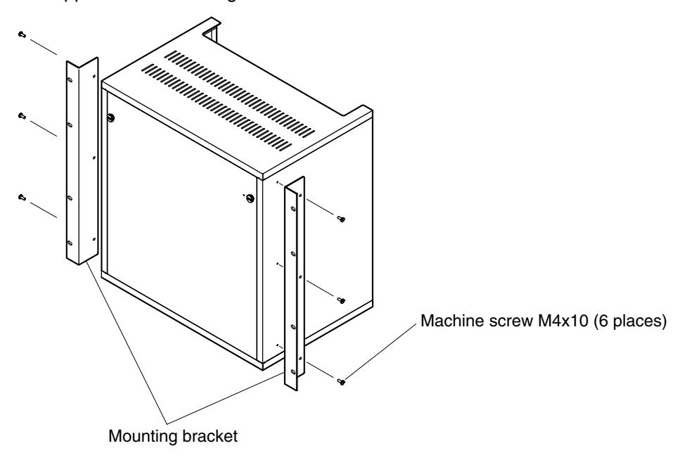
10.1.1. Rack mounting
Step 1. Attach the supplied rack mounting brackets to the frame.
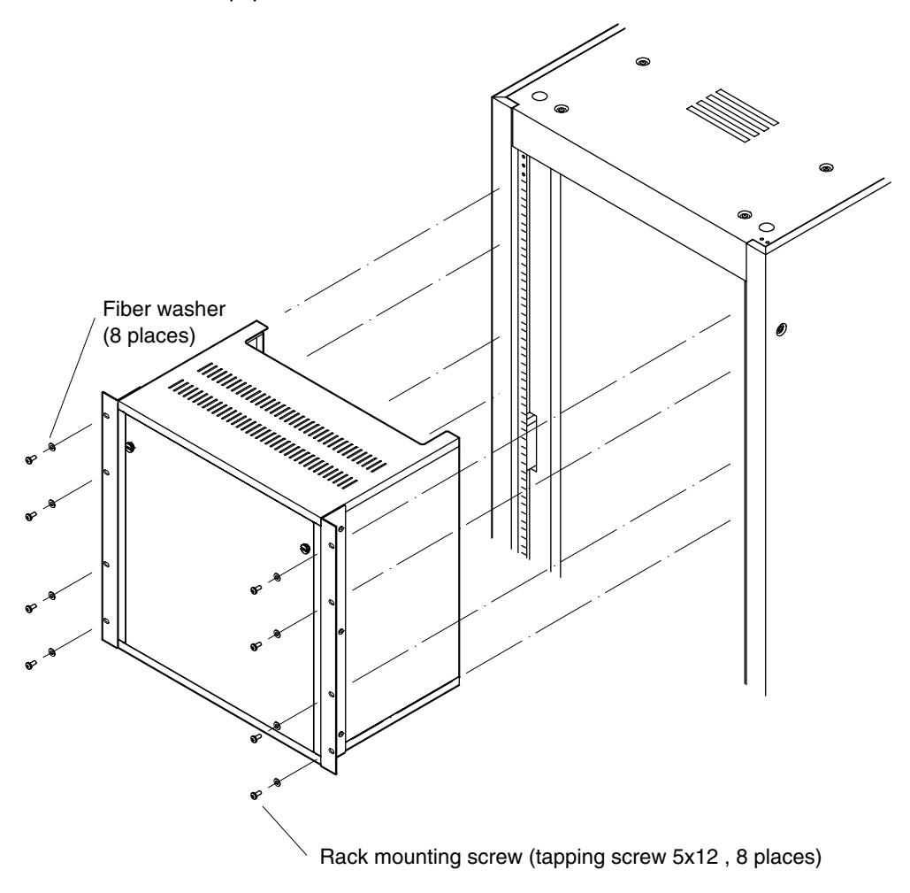
Step 2. Mount the frame to an equipment rack.
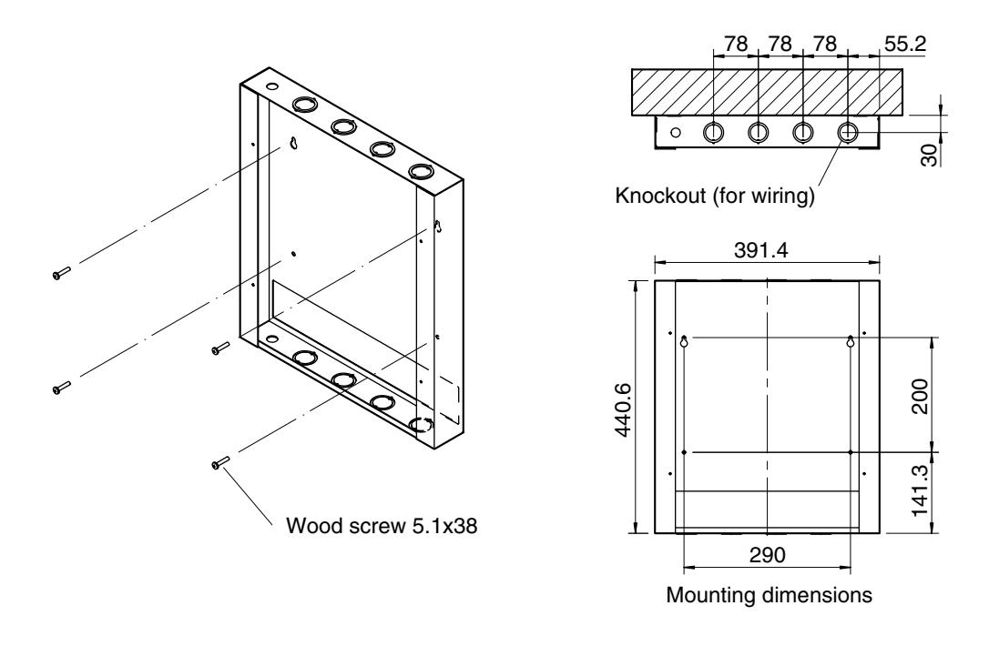
10.1.2. Wall mounting (Optional AI-YC303 Wall Mounting Frame is required.)
Step 1. Mount the AI-YC303 bracket to the wall.
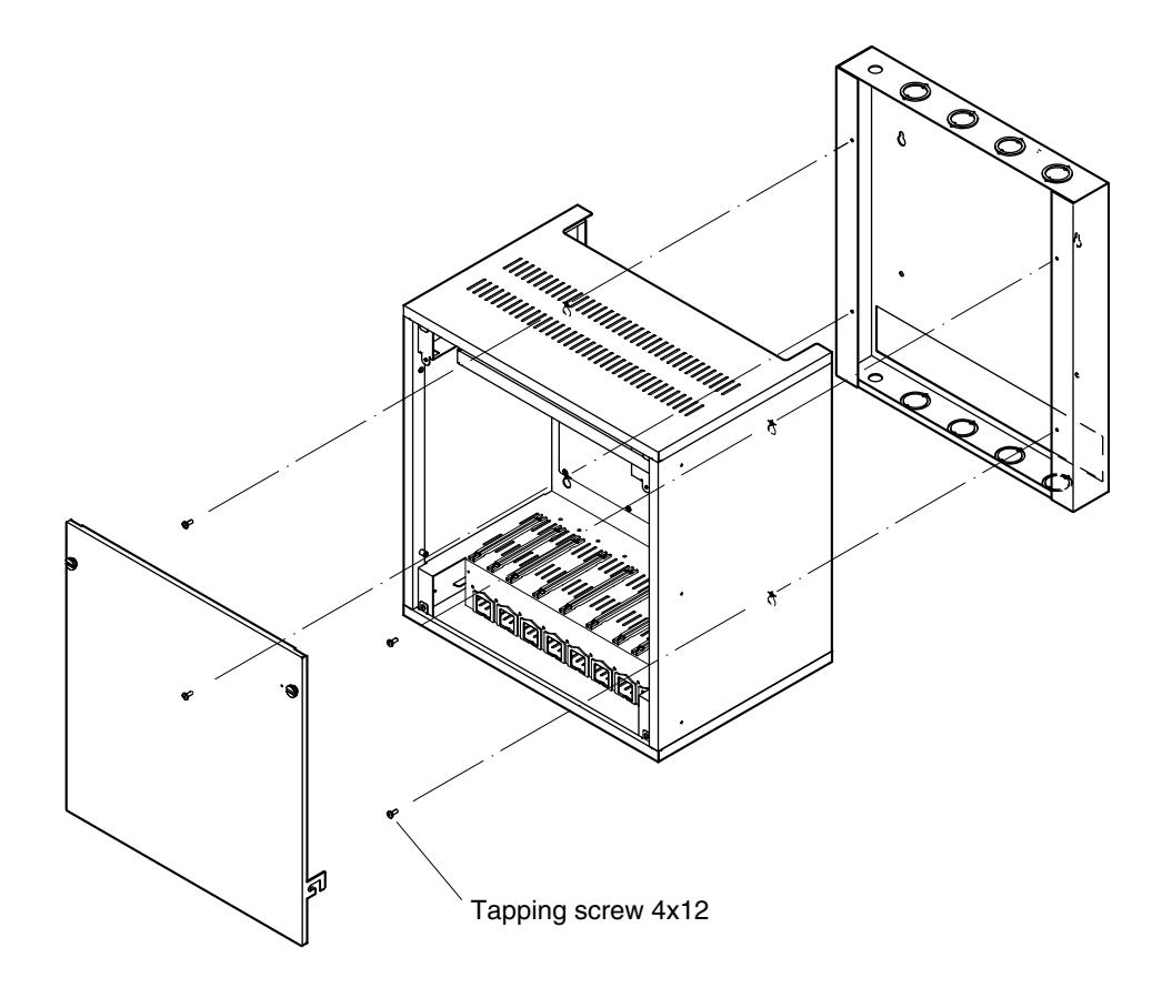
Step 2. Remove the AI-900MF's front panel, then mount the AI-900MF on the AI-YC303.
10.2. AI-PU200 Power Transformer Unit
10.2.1. Rack mounting
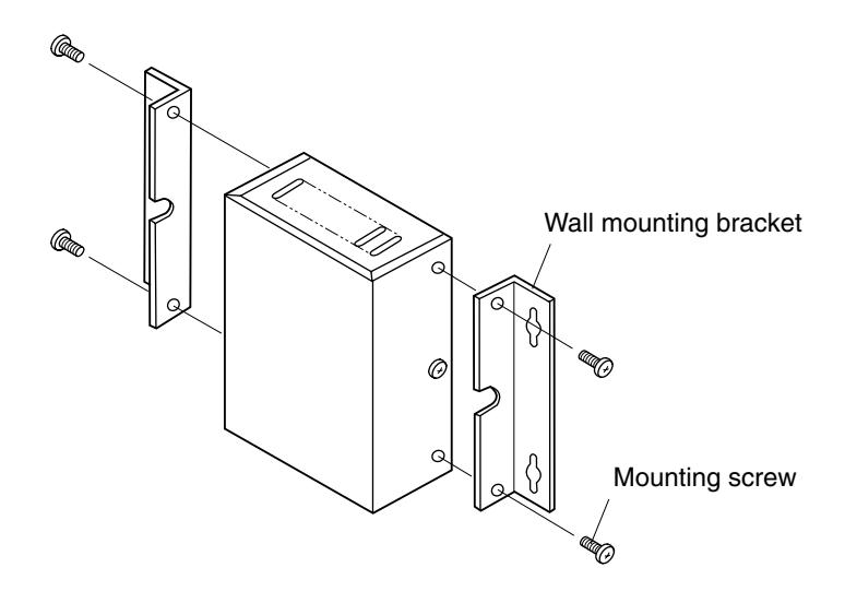
Step 1. Remove the 4 mounting screws, and attach the supplied wall mounting brackets to the transformer unit using the removed screws.
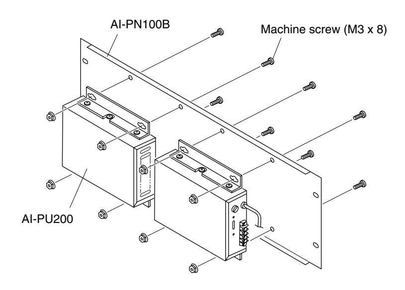
Step 2. Attach the AI-PU200 to the AI-PN100B Rack Mount Panel.
Step 3. Mount the AI-PN100B in an equipment rack.
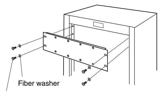
Binding head self tapping screw (5 x 12)
Note Perform terminal wiring before mounting.
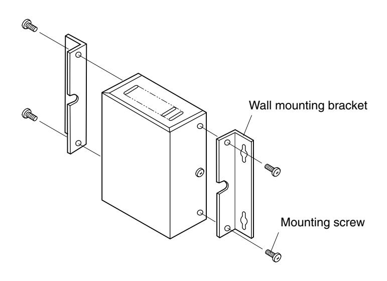
10.2.2. Wall mounting
Step 1. Remove the 4 mounting screws, and attach the supplied wall mounting brackets to the transformer using the removed screws.
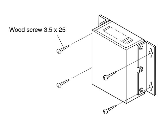
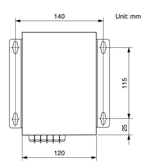
Step 2. Mount the transformer to the wall using the supplied wood screws.
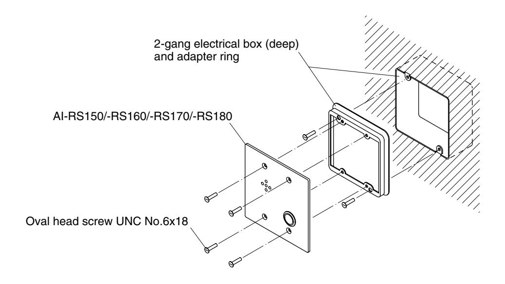
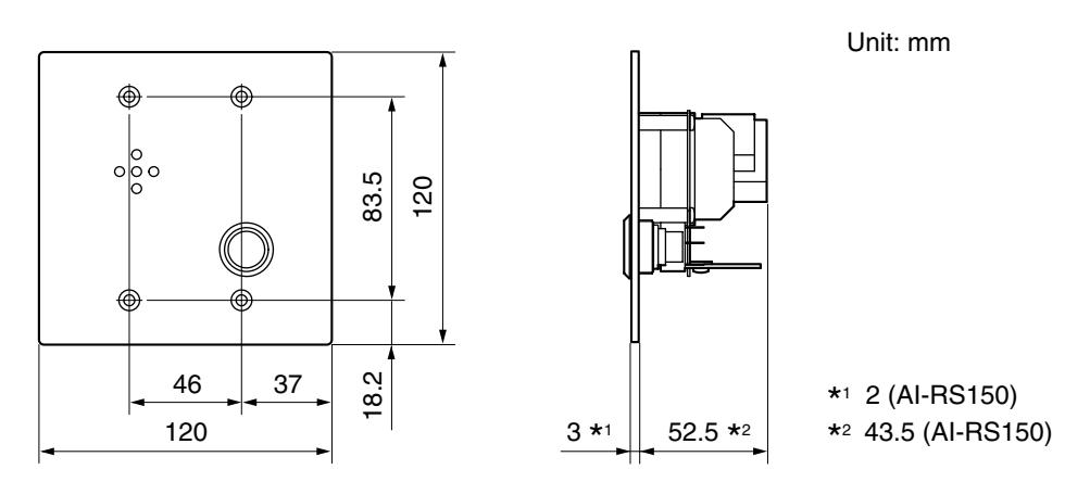
10.3. AI-RS150, AI-RS160, AI-RS170 and AI-RS180 Substations
Mount the substation to an electrical box mounted in the wall.
Dimensional diagram
10.4. Master Station
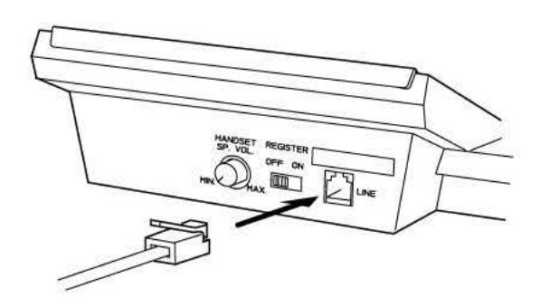
10.4.1. Desk-top mounting
Connect the supplied modular-plug cord.
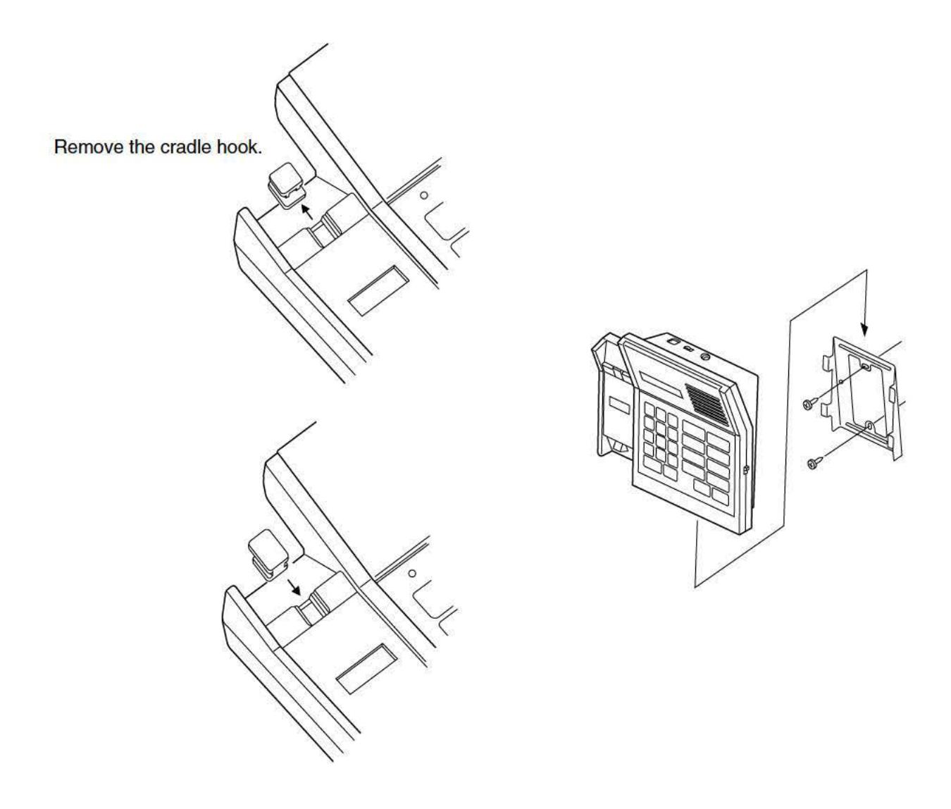
10.4.2. Wall mounting
Pull out, rotate, and reset the cradle hook, then mount the station on the wall using the supplied wall mounting frame.
11. AI-900MF CARD INSTALLATION
11.1. Backup Battery Installation
Caution
All cards contain many CMOS ICs which are easily damaged by static electricity. Do not touch circuit components.
• Insert the backup battery into the Main Frame mother board before installing any cards.
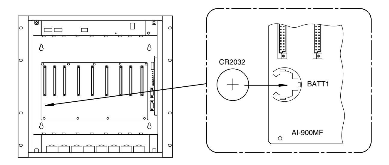
Battery replacement
As the battery life is rated at about 4 years, replace it with a new one every 4 years. Follow the replacement procedure below.
- Step 1. Switch the Main Frame (AI-900MF) power off.
- Step 2. Remove all installed cards.
- Step 3. Switch the AI-900MF power on.
- Step 4. Replace the battery.
- Step 5. Switch the AI-900MF power off.
- Step 6. Reinstall the removed cards.
- Step 7. Switch the AI-900MF power on.
Important
Be sure to replace the battery while the AI-900MF power is on.
Otherwise, stored date and time data will be lost.
CAUTION
Danger of explosion if battery is incorrectly replaced.
Replace only with the same or equivalent type recommended by the manufacturer. Dispose of used batteries according to the manufacturer's instructions.
ATTENTION
Danger d'explosion lorsque la batterie n'est pas remplacée correctement. Remplacer uniquement avec des batteries identiques ou d'un type équivalent.
11.2. Card Installation
Step 1. Remove each card from its static-protective bag, and install it in its designated position in the Main Frame.
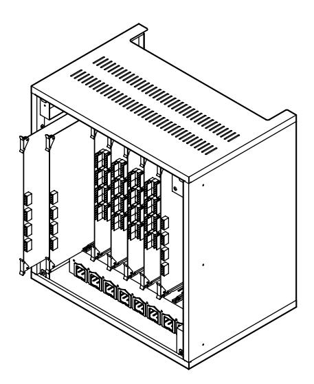
• For the AI-900TI, perform exchange number setting BEFORE installation. Refer to p. 38 "Exchange Number Setting."
Step 2. After installing all cards, secure them using the supplied fixing bracket.
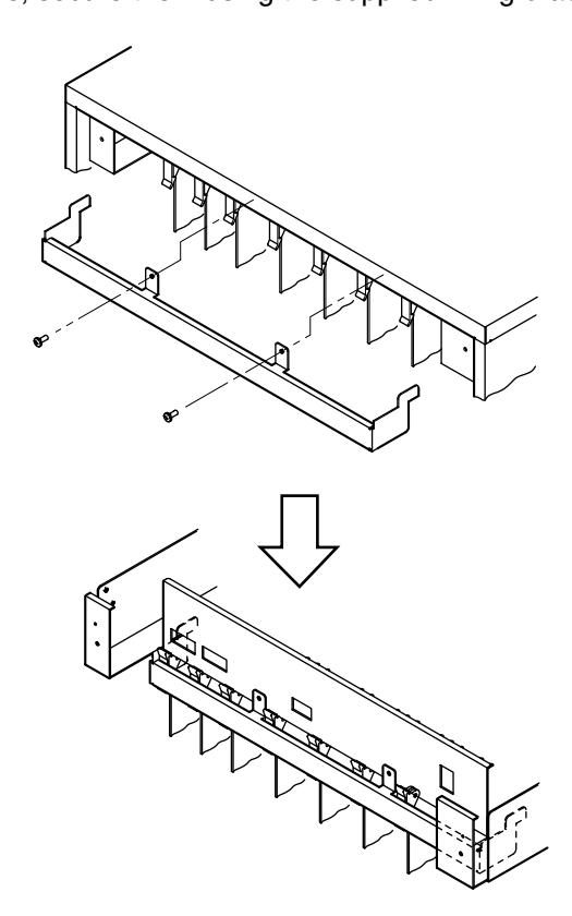
The top and side panels are omitted to show the hidden parts.
12. WIRING
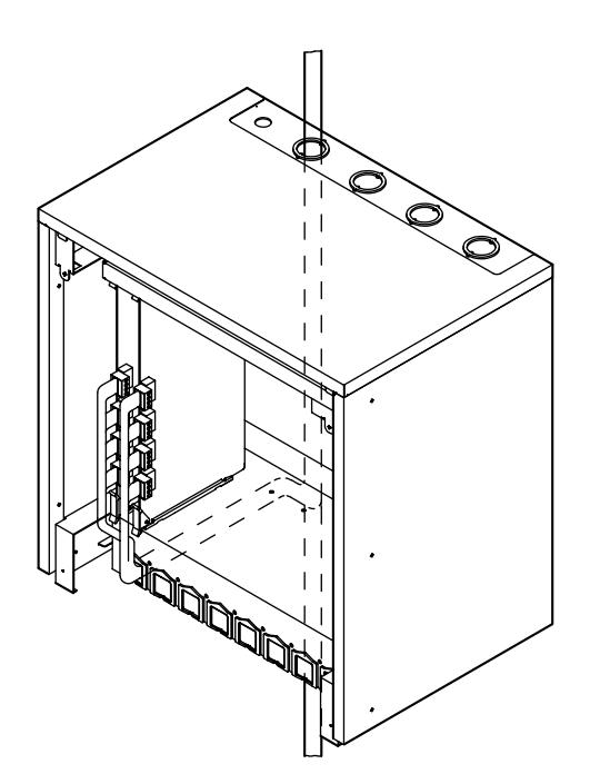
12.1. Wiring from the Station or Outside Line
Step 1. Remove the main frame's bottom panel as shown below.
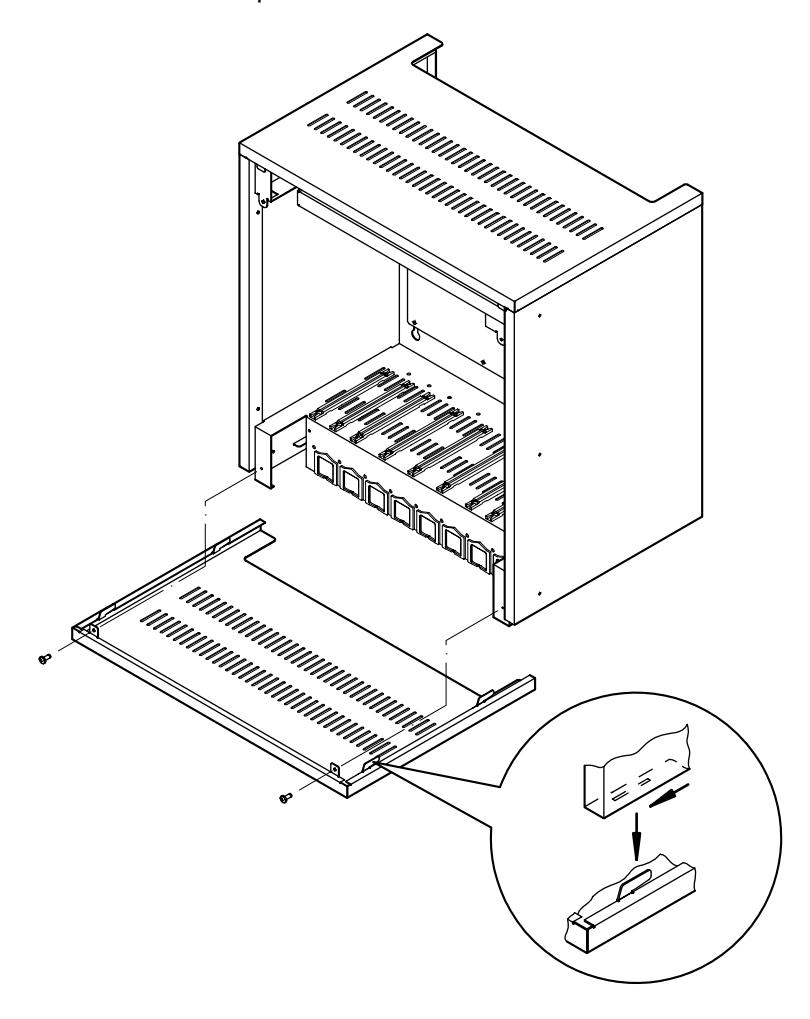
Step 2. Connect stations or outside lines to their respective cards as shown below.
12.2. Supplied Connector Connection
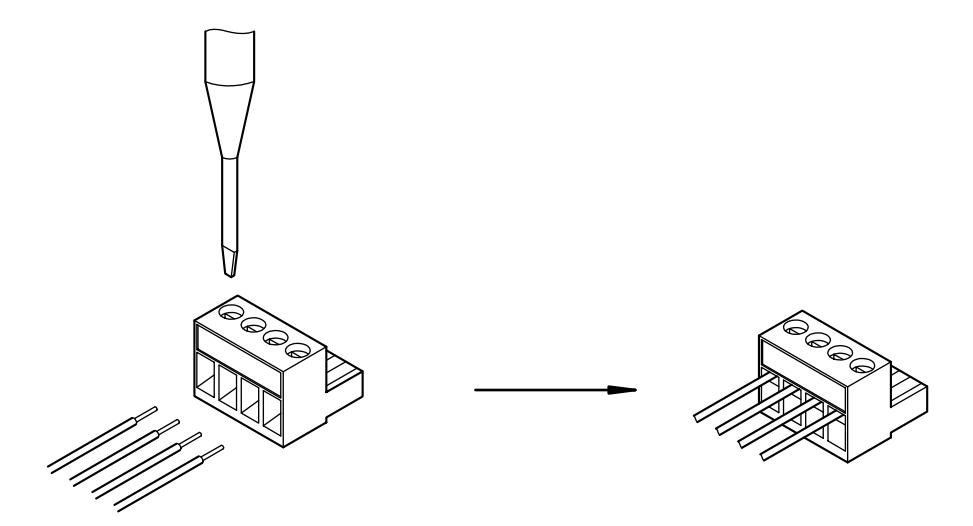
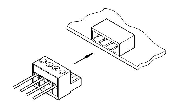
Use the supplied connectors for exchange connections as follows.
Step 1. Insert a cable into the connector and tighten the screw.
Step 2. After cable connection is completed, press the connector onto the circuit board's connector.
12.3. AI-900MS Master Station Interface Card Connection
12.3.1. Master Station and Al-900MS connection
- The AI-900MS can be interfaced with up to 2 AI-MS900 master stations.
- Because up to 2 Al-900MS cards can be mounted in the Al-900MF Main Frame, up to four master stations can be connected per frame.
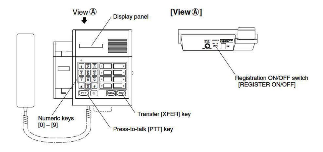
- A station address must be assigned to each connected AI-MS900 station. Set the station address at each AI-MS900 station after switching ON the power.
[Station Address Setting]
- Step 1. Set the Master Station's REGISTER switch to the ON position. The "Reg_mode" indication will be displayed on the station screen.
- Step 2. Press the [XFER] key.
- Step 3. According to the following table, enter the station address 1 4 through the use of a numeric keypad.
| AI-900MS | Line | Station Address |
|---|---|---|
| MS/AL Slot 1 | 1 | 1 |
| 2 | 2 | |
| MS/AL Slot 2 | 1 | 3 |
| 2 | 4 |
Step 4. Press the [PTT] key.
Step 5. Set the REGISTER switch to the OFF position to places the station in standby mode.
[Connection]
Use 2 twisted pair cables with a modular jack fitted at each one end to connect the AI-MS900 to the AI-900MS. Refer to the following table for the maximum recommended cable length between the two.
| Cable type | AWG24 (0.52 mm) | AWG22 (0.65 mm) | AWG20 (0.82 mm) |
|---|---|---|---|
| Distance | 0.9 km | 1.5 km | 2.3 km |
Connect as shown below.
AI-900MS and AI-MS900 connection
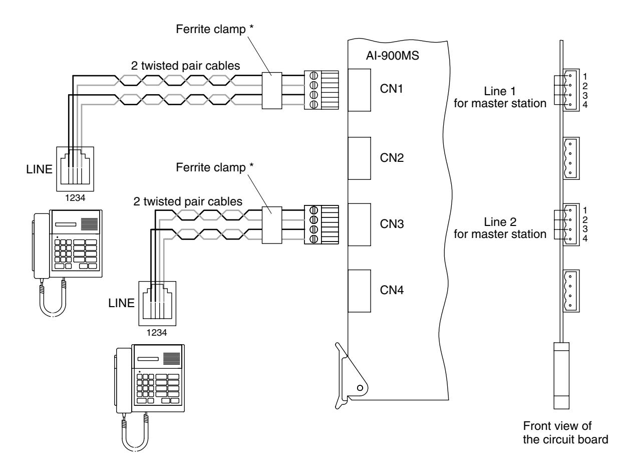
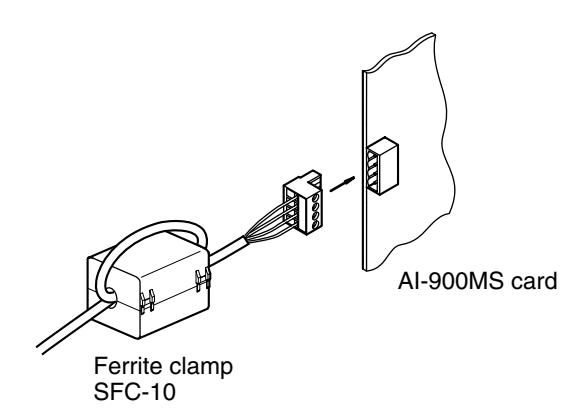
* Mount the ferrite clamp (supplied with the AI-900MS card) on the cable in a way that the cable is looped one turn as illustrated. (This countermeasure is for complying with the CE marking and FCC requirements.)
Note
When using a shielded cable, connect the shielded wire to the "FG" terminal of the exchange main frame. Also, connect the unused cables, if included in a bundle of cables, to the same terminal.
12.3.2. External recording device and AI-900MS connection
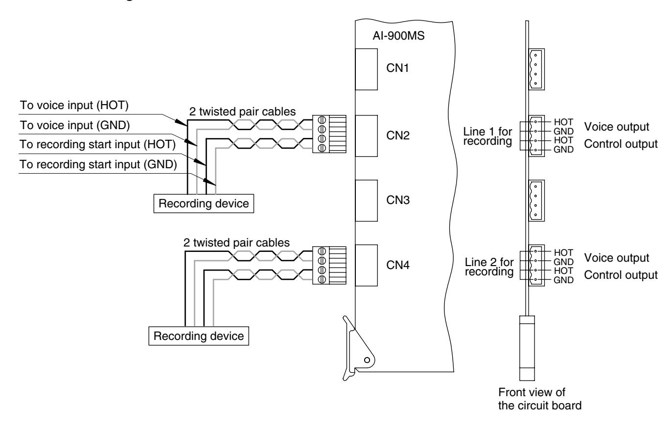
An external recording device can be connected to each master station line.
[Connection]
To connect the external recording device, use a twisted pair cable for voice output, and a twisted pair cable for control output. The voice output is 0 dB* and of unbalanced type. The control output is an open collector output 20 mA, 24 V DC max. Connect as shown below. *0 dB = 1 V
External recording device and AI-900MS connection
12.4. AI-MS900 Master Station Connection and Adjustment
12.4.1. External speaker connection
Follow the procedures below when connecting an external speaker (8Ω).
Step 1. Remove the AI-MS900's rear terminal cover and set the internal slide switch to the [EXT. SP] position.
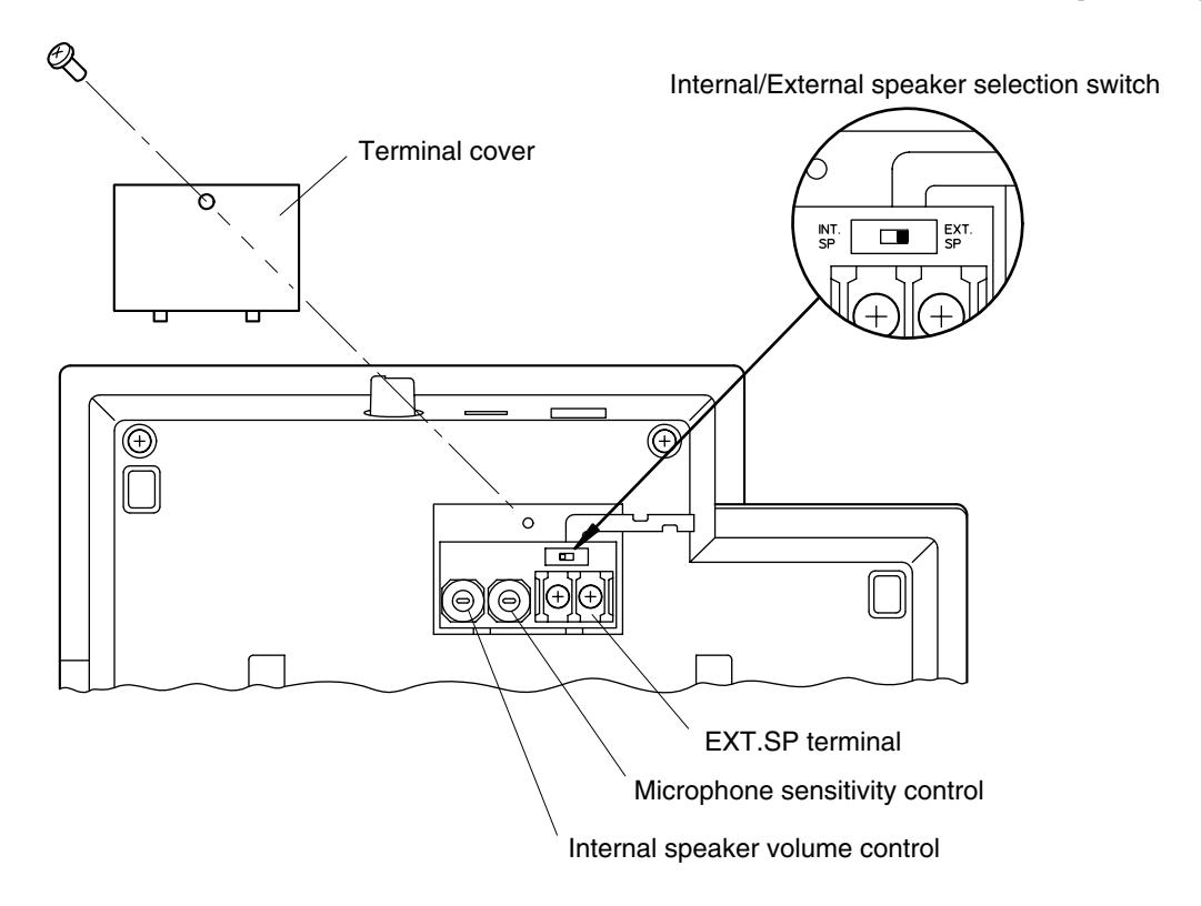
Step 2. Connect the speaker cable to EXT.SP terminal.
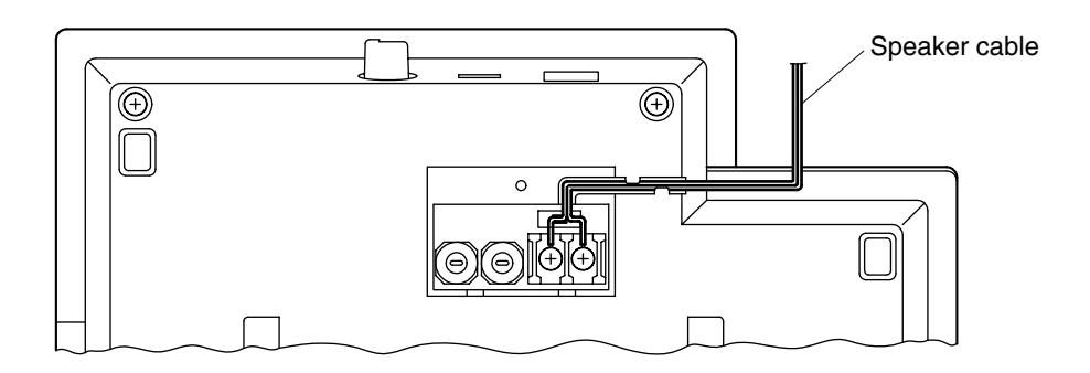
Step 3. Replace the removed terminal cover in place.
12.4.2. Internal speaker volume and microphone sensitivity adjustment
The AI-MS900's internal speaker volume and microphone sensitivity can be adjusted by means of their respective controls located under the terminal cover described above. Both controls are factory-preset to their maximum positions.
12.5. AI-900AL Telephone Interface Card Connection
12.5.1. Telephone and AI-900AL connection
The AI-900AL can be interfaced with up to 2 commercial telephone sets. Use the telephone which complies with the FCC Regulation Part 68.
[Connection]
To connect the telephone set to the AI-900AL, use a twisted pair cable. The connector of the cable end going to the telephone needs to be the type that can be connected to the telephone connector. Perform wiring as shown below so that the loop resistance is less than 500 Ω including the telephone resistance.
Telephone and AI-900AL connection
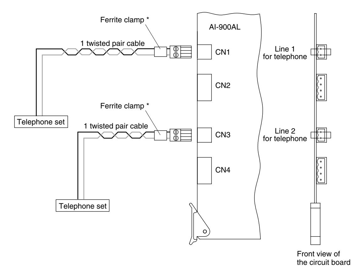
* Mount the ferrite clamp (supplied with the AI-900AL card) on the cable in a way that the cable is looped one turn as illustrated. (This countermeasure is for complying with the CE marking and FCC requirements.)
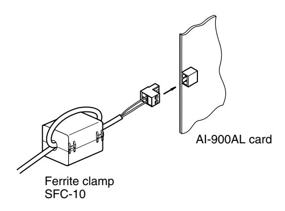
Note
When using a shielded cable, connect the shielded wire to the "FG" terminal of the exchange main frame. Also, connect the unused cables, if included in a bundle of cables, to the same terminal.
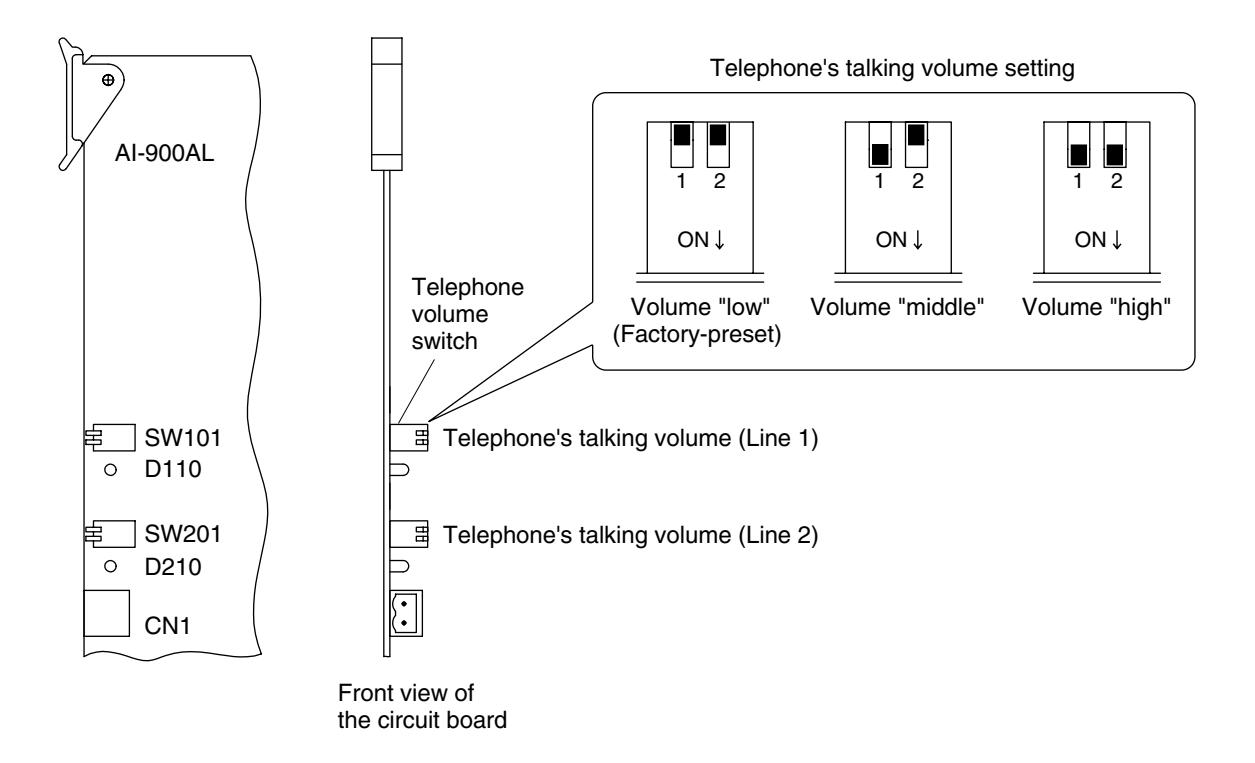
[Setting telephone's talking volume levels]
When the talking volume is low, set it using the switch SW101 (for Line 1) or SW201 (for Line 2) on the AI-900AL card as illustrated below.
Setting of telephone volume switches on the AI-900AL card
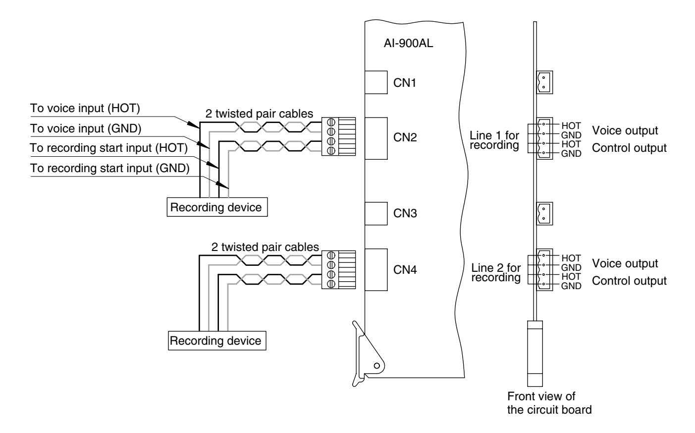
12.5.2. External recording device and AI-900AL connection
An external recording device can be connected to each telephone line.
[Connection]
To connect the external recording device, use a twisted pair cable for voice output, and a twisted pair cable for control output. The voice output is 0 dB* and of unbalanced type. The control output is an open collector output of 20 mA, 24 V DC max. Connect as shown below. *0 dB = 1 V
External recording device and AI-900AL connection
12.6. AI-900RS Substation Interface Card Connection
12.6.1. Substation and AI-900RS connection
The AI-900RS can be interfaced with up to 16 substations.
[Connection]
Use a 2-core shield cable to connect the substation to the AI-900RS. Refer to the following table for the maximum recommended cable length between the two.
| Cable type | AWG24 (0.52 mm) | AWG22 (0.65 mm) | AWG20 (0.82 mm) |
|---|---|---|---|
| Distance | 0.5 km | 0.8 km | 1.3 km |
Connect as shown below.
Connection of the AI-RS150/-RS160/-RS170/-RS180 to the AI-900RS
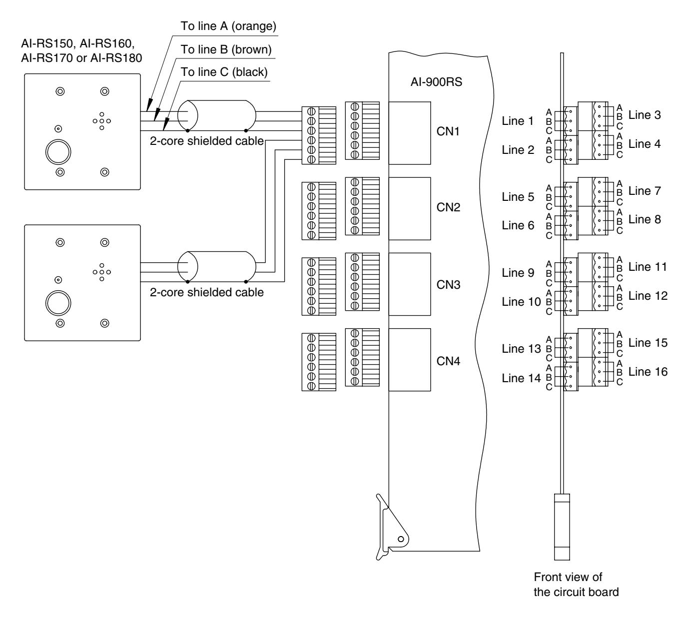
Note
The cables coming from the substations are bared at their ends.
12.6.2. External amplifier and AI-900RS connection
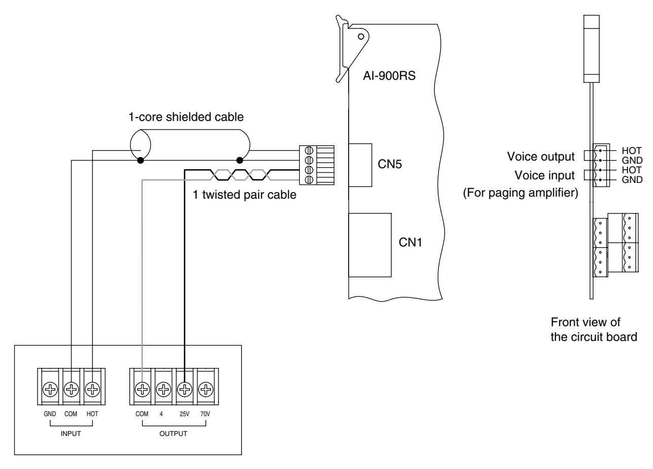
Paging amplifier *1
Electrical characteristics of the CN5 connector
Voice output: Unbalanced, –20 dB*2 signals to be sent to a paging amplifier Voice input: Balanced, acceptable signals on the 25 V line output from a paging amplifier
*1 Rated at over 16 W power output (ex. BG-130 30 W amplifier)
*2 0 dB = 1 V
12.7. AI-900CO Outside Line Interface Card Connection
12.7.1. Outside line and AI-900CO connection
The AI-900CO can be interfaced with up to 2 outside lines. Using DTMF tone dialing, it is compatible with both loop and ground start systems.
[Connection]
Connect as shown below.
Outside line and AI-900CO connection
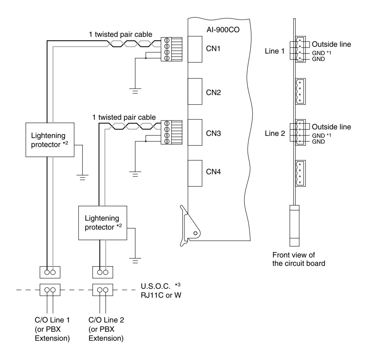
*1 Ground this terminal only when using ground start system.
*2 Install a protector if not yet installed by the telephone company.
*3 This terminal must be installed by the telephone company.
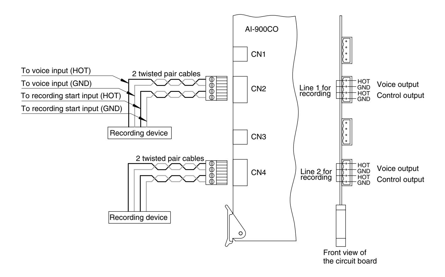
12.7.2. External recording device and AI-900CO connection
An external recording device can be connected to each telephone line.
[Connection]
To connect the external recording device, use a twisted pair cable for voice output, and a twisted pair cable for control output. The voice output is 0 dB* and of unbalanced type. The control output is an open collector output o f 20 mA, 24 V DC max. Connect as shown below. *0 dB = 1 V
External recording device and AI-900CO connection
12.8. Al-900AF Audio Function Card Connection
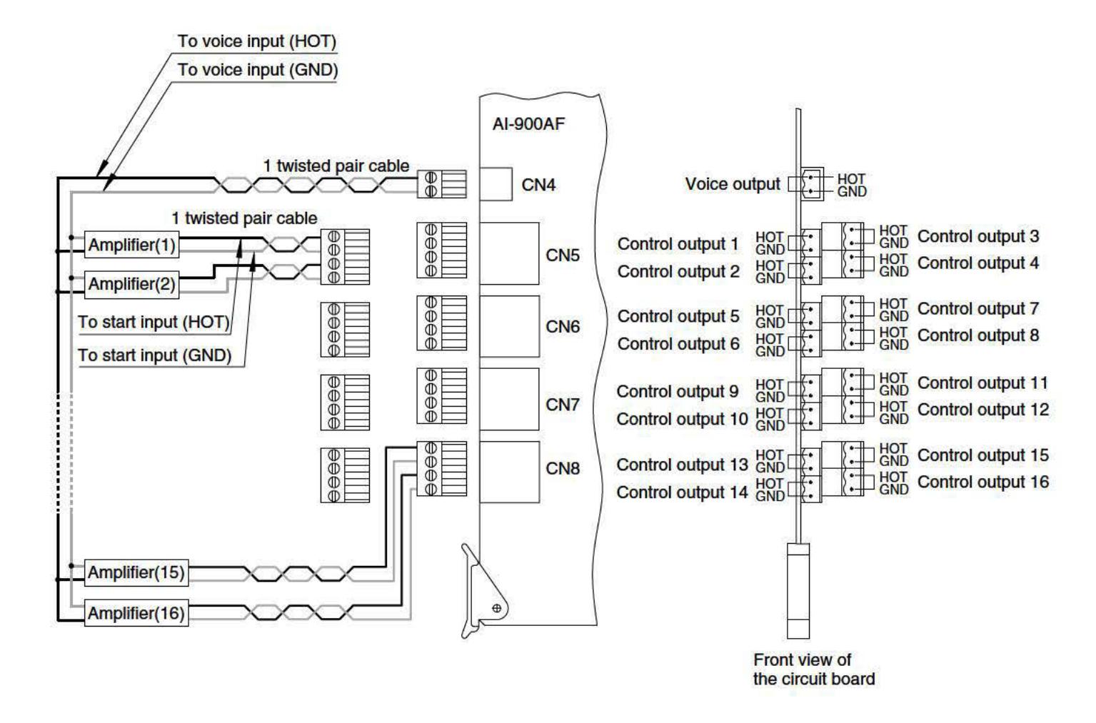
12.8.1. Amplifier and Al-900AF connection
Paging can be provided through connected external amplifiers using the Al-900AF.
[Connection]
To connect the amplifier to the AI-900AF, use a twisted pair cable for voice output, and a twisted pair cable for control output. The voice output is 0 dB* and of unbalanced type. The control output is an open collector output of 20 mA, 24 V DC max., and permits connection of up to 16 channels. Connect as shown below. *0 dB = 1 V
External amplifier and AI-900AF connection
12.8.2. External sound source and AI-900AF connection
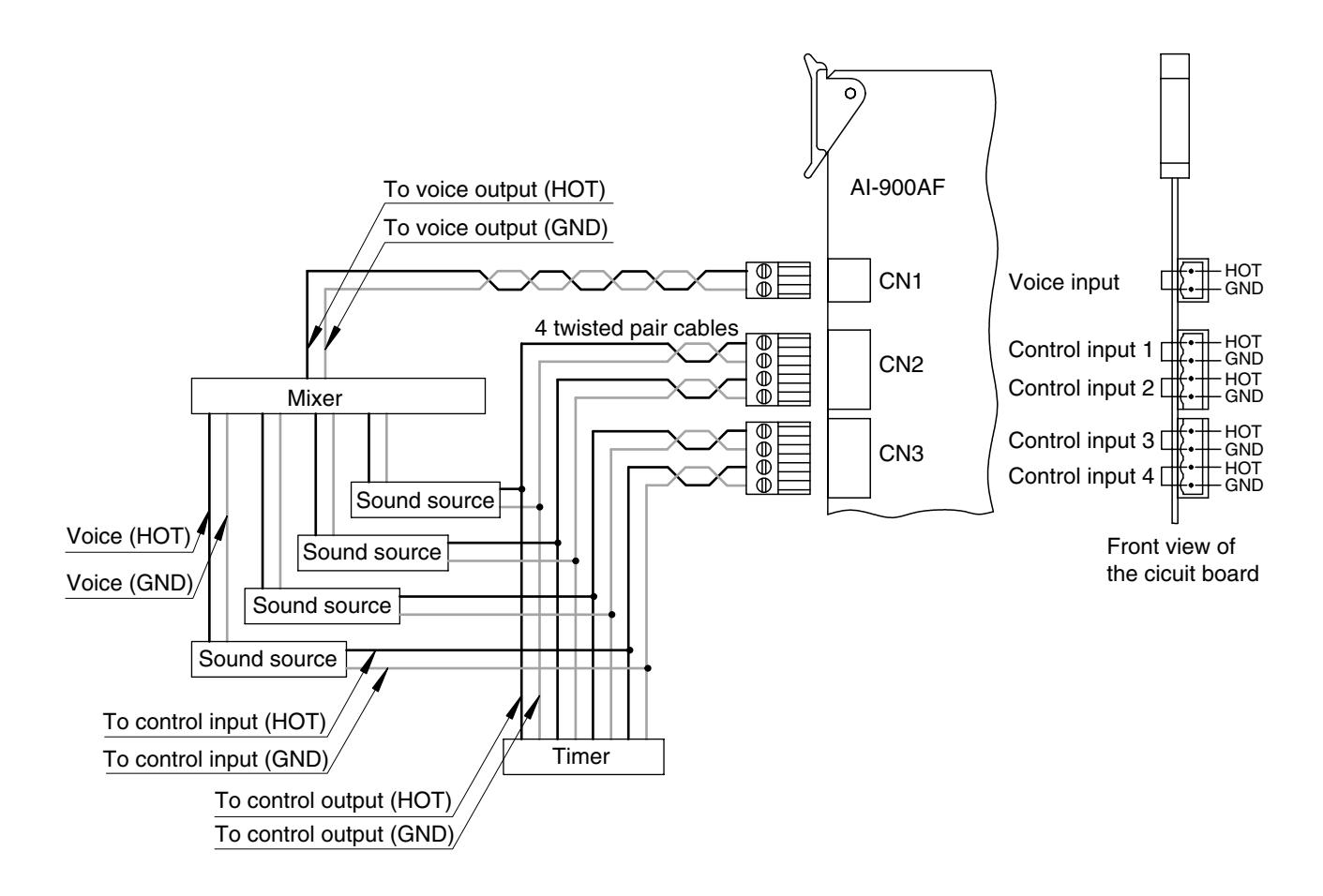
The External Sound Source Distribution function can be operated using the AI-900AF.
[Connection]
To connect external sound sources to the AI-900AF, use a twisted pair cable for voice input, and a twisted pair cable for control input (level-operated activation). The voice input is 0 dB* and of unbalanced type. The start input is a no-voltage make contact of 20 mA, 24 V DC max. Connect as shown below. *0 dB = 1 V
External sound sources and AI-900AF connection
12.9. AI-900TI Tie-Line Interface Card Exchange Interconnection
Up to 16 exchanges can be tie-line interconnected using the AI-900TI card.
[Connection]
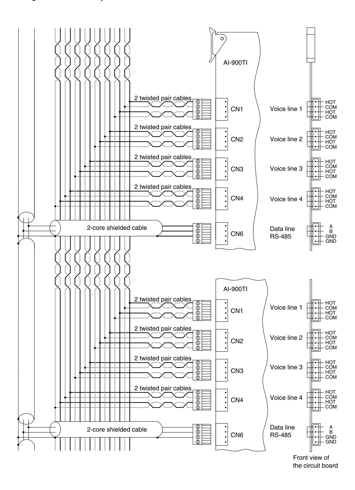
To interconnect the exchanges, use 2 twisted pair cables for voice lines, and a 2-core shielded cable for data lines. A maximum of 4 voice lines can be connected. Refer to the following table for the maximum recommended length for each cable type between exchanges. (As to the cable connection, see the figure on the next page.)
| Cable type | AWG24 (0.52 mm) | AWG22 (0.65 mm) | AWG20 (0.82 mm) |
|---|---|---|---|
| Distance | 0.6 km | 1 km | 1.5 km |
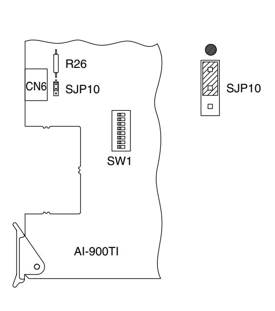
[Termination resistance setting]
When interconnecting three or more exchanges, change the SJP10 connection on each card as shown below, with the exception of the cards in the rightmost and leftmost exchanges.
Factory-preset status of SJP10 Termination resistance setting when interconnecting 3 or 4 exchanges
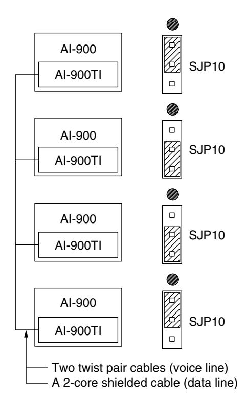
Exchange interconnection by means of AI-900TI
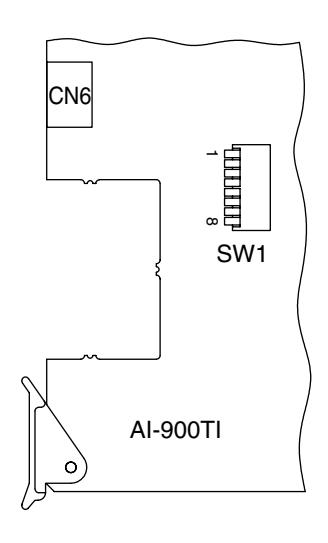
[Exchange Number Setting]
When interconnecting the exchanges using the AI-900TI, assign the exchange number to each exchange with the SW1 switch located on the AI-900TI's circuit board. (Refer to the table below.)
Exchange No. setting
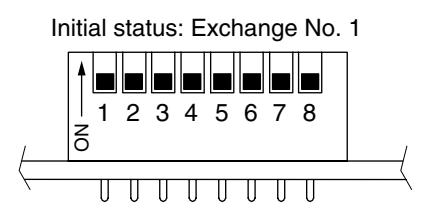
| Exchange No. | 1 | 2 | 3 | 4 | 5 – 8 |
|---|---|---|---|---|---|
| 1 | OFF | OFF | OFF | OFF | OFF |
| 2 | ON | OFF | OFF | OFF | OFF |
| 3 | OFF | ON | OFF | OFF | OFF |
| 4 | ON | ON | OFF | OFF | OFF |
| 5 | OFF | OFF | ON | OFF | OFF |
| 6 | ON | OFF | ON | OFF | OFF |
| 7 | OFF | ON | ON | OFF | OFF |
| 8 | ON | ON | ON | OFF | OFF |
| 9 | OFF | OFF | OFF | ON | OFF |
| 10 | ON | OFF | OFF | ON | OFF |
| 11 | OFF | ON | OFF | ON | OFF |
| 12 | ON | ON | OFF | ON | OFF |
| 13 | OFF | OFF | ON | ON | OFF |
| 14 | ON | OFF | ON | ON | OFF |
| 15 | OFF | ON | ON | ON | OFF |
| 16 | ON | ON | ON | ON | OFF |
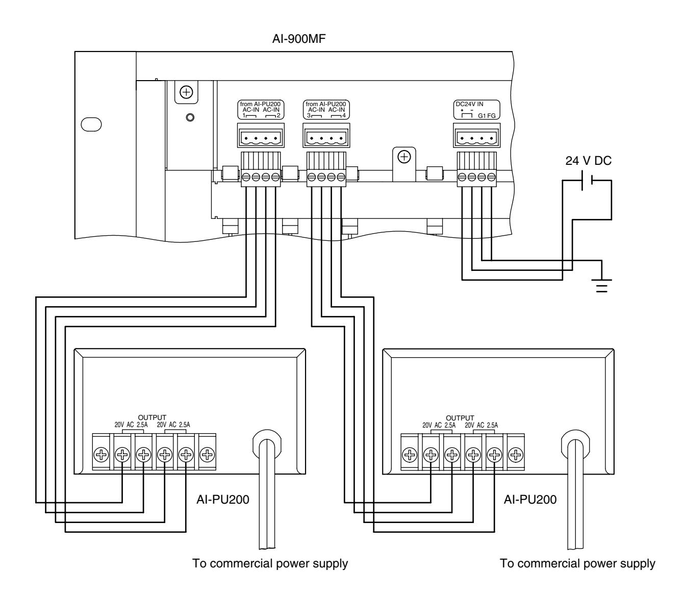
12.10. AI-900MF Main Frame and AI-PU200 Power Transformer Connection
[Connection]
Connect as shown below using 2 parallel pair cables. Use cables with a sufficient current capacity and a heavier gauge than AWG18. Two AI-PU200 units are required when using 3 or 4 AI-900RS cards.
AI-900MF and power supply connection
13. MAIN FRAME AND PC CONNECTION
13.1. Programming PC Connection
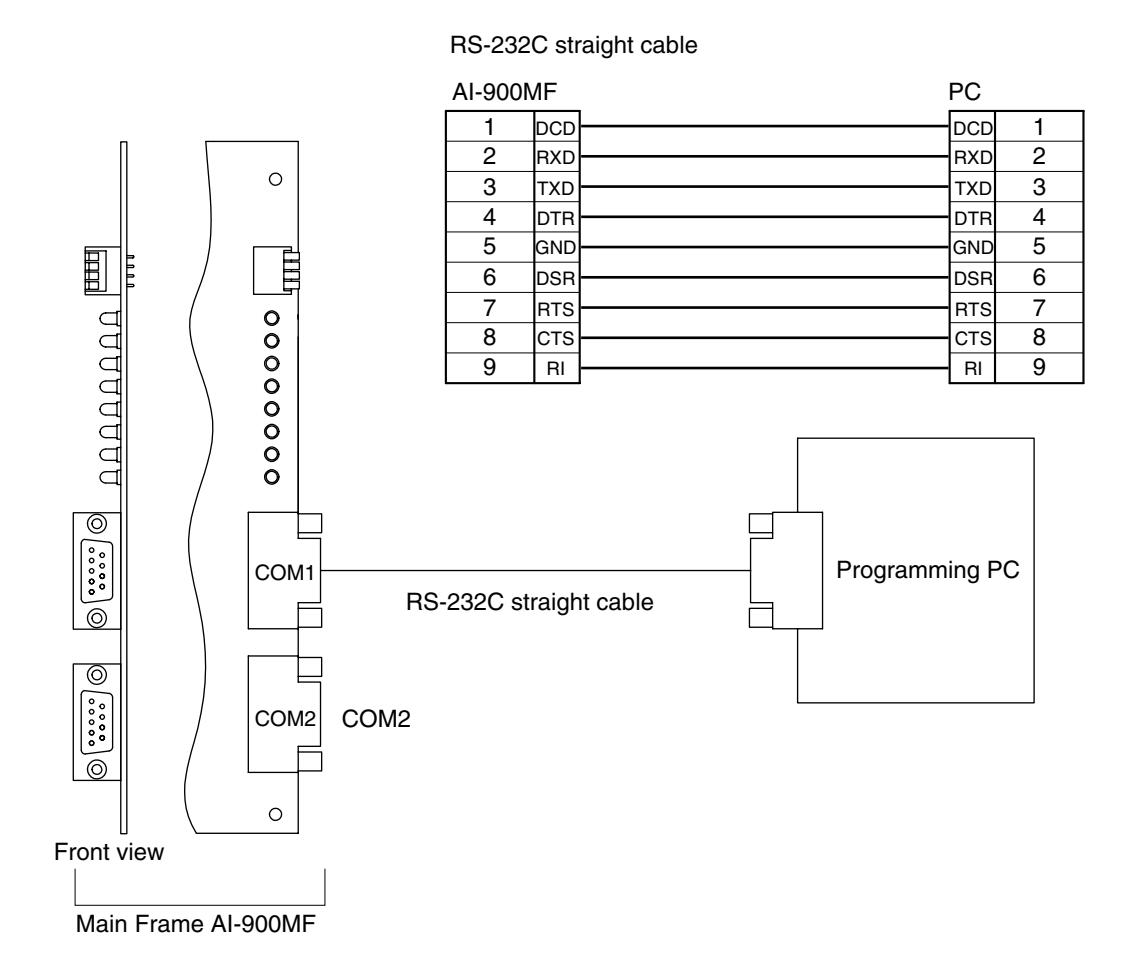
13.1.1. Direct connection by means of RS-232C
Using the RS-232C cable, connect the programming PC to the AI-900MF Main Frame as shown below.
Direct connection by means of RS-232C (Programming PC)
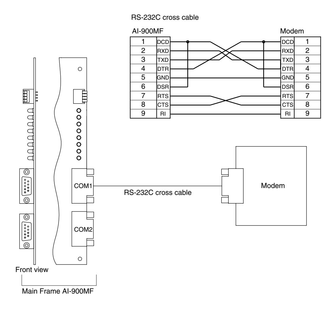
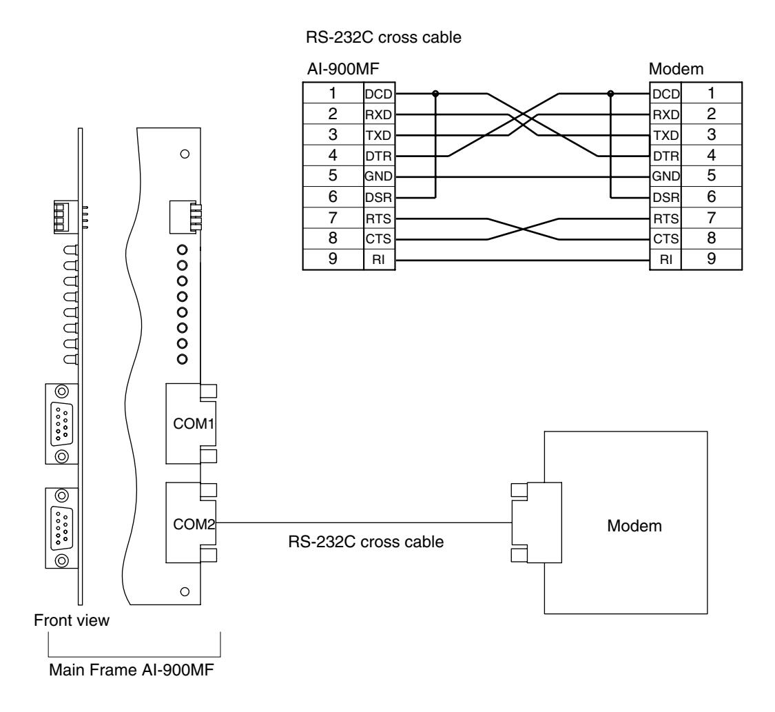
13.1.2. Connection via modem
Connect as shown below.
Connection via modem (Programming PC)
13.2. Operation Log PC Connection
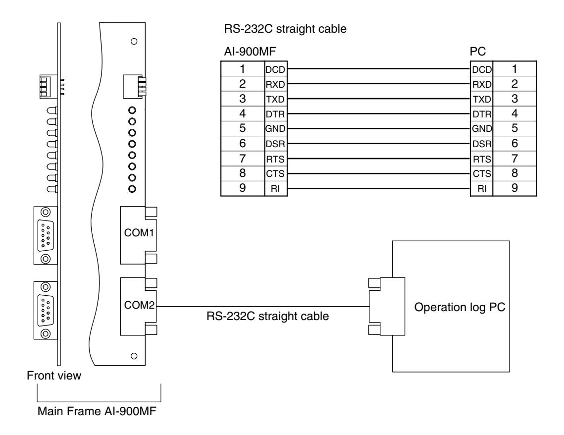
13.2.1. Direct connection by means of RS-232C
Using the RS-232C cable, connect the operating log PC to the AI-900MF as shown below.
Direct connection by means of RS-232C (Operation log PC)
13.2.2. Connection via modem
Connect as shown below.
Connection via modem (Operation log PC)
13.3. System Programming
Use the supplied PC software to perform such system programming as station number and function settings. For its use and installation, refer to the "AI-900 Setup Software Instruction Manual."
14. SPEECH AND FUNCTION TESTS
Using installed equipment, perform both speech and function tests after system programming completion.
14.1. Speech Test
(1) Calls from the substation
- Call the Master Station (telephone) from each substation to check to be sure that a conversation is possible. Also, check to confirm that the master station (telephone) registered in system programming is correctly called.
- Check to be sure that the calling substation number (name) is correctly displayed on the Master Station.
(2) Calls from the master station
- Call the substation and Master Station from each Master Station to check to be sure that a conversation is possible.
- Check to confirm that the designated station is correctly called.
14.2. Function Test
Check each function registered in system programming for correct operation. For each function's operation, refer to the "AI-900 OPERATING INSTRUCTIONS."
15. SPECIFICATIONS
[AI-900MF Main Frame]
| Power Source | 20 V AC, 24 V DC | |||
|---|---|---|---|---|
| Current Consumption | 5.5 A | |||
| Speech Path Configuration | Time sharing switch (T1 stage) | |||
| Serial port | Complies with the RS-232C Standard, D-sub connector (9-pin, female), | |||
| 2 ports | ||||
| Installation Method | Rack- and wall-mountable | |||
| Other | Real time clock for time control | |||
| Unit's presence/non-presence detection | ||||
| System programming data maintenance | ||||
| Power switch | ||||
| Connection Terminal |
Bus connector:
DIN connector (64-pin, female) x 9 |
|||
| AI-PU200 connection terminal: 4-pin x 2 (2 AI-PU200s are connectable.) | ||||
|
24 V DC input terminal:
4-pin (with grounding terminal) |
||||
| Operating Temperature | 0 – 40°C | |||
| Finish | Pre-coated steel plate, black, 30% gloss | |||
| Dimensions | 420 (w) x 443.7 (h) x 288.3 (d) mm (excluding the rack mounting bracket) | |||
| Weight | 12.7 kg | |||
Note: The design and specifications are subject to change without notice for improvement.
• Accessories
| Rack mounting bracket 2 | AI-900 operating instructions 1 |
|---|---|
| Machine screw (M4 x 10) 6 | AI-900 installation manual (this manual) 1 |
| Cable clip 20 | AI-900 setup software manual 1 |
| 4-pin dedicated connector 3 | Rack mounting screw 8 |
| CR2032 battery 1 | Rack mounting washer 8 |
| Floppy disk (PC setting software) 2 |
[AI-900MS Master Station Interface Card]
| Power Source | 5 V DC, 24 V DC (supplied from the main frame) | ||
|---|---|---|---|
| Current Consumption | 50 mA (5 V DC), 200 mA (24 V DC) | ||
| Supply Power | 24 V DC, 80 mA | ||
| Number of Lines | 2 lines | ||
| Conversation Recording Output |
Audio signal:
0 dB*, unbalanced |
||
| Control signal: Open collector output, withstand voltage: 24 V DC, | |||
| control current: 20 mA | |||
| Connection Terminal |
Main frame connection side:
DIN connector (64-pin, male) |
||
|
Line output:
4-pin x 2 |
|||
| Recording audio/control output: 4-pin x 2 | |||
| Weight | 350 g | ||
* 0 dB = 1 V
Note: The design and specifications are subject to change without notice for improvement.
• Accessories
| 4-pin dedicated connector 4 | |
|---|---|
| Ferrite clamp SFC-10 2 |
[AI-900AL Telephone Interface Card]
| Power Source | 5 V DC, 15 V DC, 24 V DC (supplied from the main frame) | ||
| Current Consumption | 150 mA (5 V DC), 30 mA (15 V DC), 200 mA (24 V DC) | ||
| Supply Power | 24 V DC, 80 mA | ||
| Number of Lines | 2 lines | ||
| Conversation Recording Output |
Audio signal:
0 dB*, unbalanced |
||
| Control signal: Open collector output, withstand voltage: 24 V DC, | |||
| control current: 20 mA | |||
| Selectable Signal Type | DTMF signal | ||
| Monitoring Function | Line loop detection function | ||
| Applicable Terminal | Telephone sets to comply with FCC Part 68 | ||
| Control Function | Call signal transmission, audible signal transmission, | ||
| caller identification signal transmission (Caller ID Function) | |||
| Connection Terminal |
Main frame connection side:
DIN connector (64-pin, male) |
||
|
Line output:
2-pin x 2 |
|||
| Recording audio/control output: 4-pin x 2 | |||
| Weight | 400 g | ||
* 0 dB = 1 V
Note: The design and specifications are subject to change without notice for improvement.
• Accessories
| 2-pin dedicated connector 2 | |
|---|---|
| 4-pin dedicated connector 2 | |
| Ferrite clamp SFC-10 2 |
[AI-900RS Substation Interface Card]
| Power Source | 5 V DC, 24 V DC (supplied from the main frame) |
| Current Consumption | 200 mA (5 V DC), 600 mA (24 V DC) |
| Number of Lines | Substation 16 lines |
| Number of Links | 2 links (One of 2 links is also used as a Paging Link.) |
| Paging Output | Unbalanced, –20 dB* signals to be sent to a paging amplifier |
| Paging Input | Balanced, acceptable signals on the 25 V line output from a paging |
| amplifier | |
| Conversation Method | Half-duplex conversation by voice-operated switch or simplex |
| conversation by PTT switch | |
| Supply Power | Maximum 1 W per substation |
| Other | Call button detection function and speech link control function |
| Connection Terminal | Main frame connection side: DIN connector (64-pin, male) |
|
Substation connection side:
Two-core shielded cable (3-pin) x 16 |
|
|
Paging input/paging output:
4-pin |
|
| Weight | 550 g |
* 0 dB = 1 V
Note: The design and specifications are subject to change without notice for improvement.
• Accessories
| 3-pin dedicated connector 16 | |
|---|---|
| 4-pin dedicated connector 1 |
[AI-900CO Outside Line Interface Card]
| Power Source | 5 V DC, 15 V DC, 24 V DC (supplied from the main frame) |
|---|---|
| Current Consumption | 300 mA (5 V DC), 50 mA (15 V DC), 50 mA (24 V DC) |
| Number of Lines | 2 lines |
| Conversation Recording Output |
Audio signal:
0 dB*, unbalanced |
| Control signal: Open collector output, withstand voltage: 24 V DC, | |
| control current: 20 mA | |
| Selectable Signal Type | DTMF signal |
| Signal Format | Loop start and Ground start compatible |
| Main Functions | DTMF dial signal transmission function, DTMF signal detection |
| function, call signal (receiving) detection | |
| Connection Terminal |
Main frame connection side:
DIN connector (64-pin, male) |
|
C/O line connection side:
4-pin x 2 |
|
| Recording audio/control output: 4-pin x 2 | |
| Weight | 380 g |
* 0 dB = 1 V
Note: The design and specifications are subject to change without notice for improvement.
• Accessories
4-pin dedicated connector .......................... 4
[AI-900AF Audio Function Card]
| Power Source | 5 V DC, 15 V DC, 24 V DC (supplied from the main frame) | |
|---|---|---|
| Current Consumption | 100 mA (5 V DC), 50 mA (15 V DC), 30 mA (24 V DC) | |
| Paging Output |
Audio output:
1 output, 0 dB*, unbalanced |
|
| Control output: Open collector output, withstand voltage: 24 V DC, | ||
| control current: 20 mA | ||
| External Source Distribution |
Audio input:
1 input, 0 dB*, unbalanced |
|
| Control input: 4 inputs, no-voltage make contact, | ||
| open voltage: 24 V DC, short circuit current: 20 mA | ||
| Conference Link | 1 link (up to 4-party conference) | |
| Connection Terminal | Main frame connection side: DIN connector (64-pin, male) | |
|
External interface side:
Voice output 2-pin |
||
| Control output 2-pin x 16 | ||
| Voice input 2-pin | ||
| Control input 2-pin x 4 | ||
| Weight | 230 g | |
* 0 dB = 1 V
Note: The design and specifications are subject to change without notice for improvement.
• Accessories
2-pin dedicated connector .......................... 2 4-pin dedicated connector ........................ 10
[AI-900TI Tie-Line Interface Card]
| Power Source | 5 V DC, 15 V DC (supplied from the main frame) |
|---|---|
| Current Consumption | 100 mA (5 V DC), 50 mA (15 V DC) |
| Number of Audio Links | 4 links |
| Connection Format | Multidrop system |
| Transmitting System | Data: RS-485 |
| Voice: Base band | |
| Input/Output Level | Voice: 0 dB*, balanced |
| Data: In compliance with RS-485 Standard | |
| Other | Exchange number setting function |
| Connection Terminal | Main frame connection side: DIN connector (64-pin, male) |
| Tie-line interface side: 4-pin x 4 (Voice line) | |
| 4-pin x 1 (Data line) | |
| Weight | 320 g |
0 dB = 0.775 V
Note: The design and specifications are subject to change without notice for improvement.
Accessories
4-pin dedicated connector ...... 5
[AI-YC303 Main Frame Wall Mounting Bracket]
| Finish | Steel, black, electrodeposition paint |
|---|---|
| Dimensions | 391.4 (w) x 440 (h) x 58 (d) mm |
| Weight | 2.1 kg |
Note: The design and specifications are subject to change without notice for improvement.
Accessories
Wood screw (5.1 x 38) ...................................