Aiphone AI-900 910DI Installation Manual Instruction
Open the original PDF document
View PDF


DIRECT SELECT CONTROL CARD AI-900DI DIRECT SELECT I10 CARD AI-91 OD1
Important
1. These cards contain CMOS iC's and may be damaged by static discharge. It is advisable to wear an earth-grounded wrist strap when handling the cards.
,- -
2. Turn off all power to the system before unplugging or plugging in connectors to the cards.
Please follow the instructions in this manual to obtain the optimum results from this unit. We also recommend that you keep this manual handy for future reference.
TABLE OF CONTENTS
|
1 . GENERAL DESCRIPTION
4 |
|---|
| 2 . SYSTEM CONFIGURATION AND OPERATION |
|
2.1 . System Configuration
4 |
| 2.2. Basic Operation 5 |
| 3 . NOMENCLATURE AND DIMENSIONAL DIAGRAM |
|
Direci Select Control Card AI-900DI
6 |
| Direct Select I10 Card AI-91 OD1 8 |
| 4 . SYSTEM DESIGN 9 |
| 5 . INSTALLATION |
|
5.1. Setting the AI-900DI Station Addresses
9 |
|
5.2. Setting the AI-910DI Card Numbers
10 |
|
5.3. Installing the AI-900DI/AI-91 OD1
10 |
| 5.4. AI-900DI Connection |
|
5.4.1 . Connector connection
11 |
|
5.4.2. CN2 power supply terminal connection
11 |
|
5.4.3. Connection to the exchange
12 |
| 5.4.4. Connection to the AI-MS900 Master Station 13 |
|
5.4.5. Mounting the ferrite clamp
13 |
|
5.4.6. CN5 in-use indication output connection
14 |
|
5.4.7. CN4 Input key (C/PTT/Xfer/Test key) connection
14 |
| 5.4.8. CN8 headset connection 15 |
| 5.4.9. Earth grounded connection 15 |
| 5.4.10. CN9 microphone input connection 16 |
|
5.4.1 1 . CNlO speaker output connection
16 |
| 5.5. AI-91 OD1 Connection |
|
5.5.1. CN3 power supply terminal connection
17 |
| 5.5.2. Calling station indication output connection 17 |
|
5.5.3. Direct select input connection
18 |
| 5.5.4. External equipment control output connection 19 |
|
5.5.5. AI-91 ODl's CN4/CN5/CN6 connections
20 |
| 6 . REGISTRATION |
| 6.1 . Direct Select Setting 21 |
|
6.2. Direct Select Dial Setting
21 |
|
6.3. Programming PC Connection
22 |
| 6.4. Programming Data Entry |
|
6.4.1. Entry when the AI-900DI alone is used
22 |
| 6.4.2. Entry when the AI-900DI is connected to the Al-SIODI 22 |
| 7. OPERATION TEST | |
|---|---|
| 7.1. Operation Check by Means of the Test Switch | 23 |
| 7.2. Check through Individual Operations | |
| 7.2.1. Checking AI-900DIlAI-91 OD1 for proper operation | |
| without using the master station | 23 |
| 7.2.2. Checking AI-900DIlAI-910DI for proper operation | |
| when using the master station | 23 |
| 8. FUNCTIONS AND OPERATION | |
| 8.1 . CallingICalled Station Indication Output | 24 |
| 8.2. Direct Select Input | 25 |
| 8.3. External Equipment Control Output | |
| 8.3.1. CCTV interlock output | 26 |
| 8.3.2. Remote door control output | 27 |
| 8.4. Conversation Using the Master Station | 28 |
| 8.5. Conversation Using the Al-900DI and Not Using the Master Station 28 | |
| 9. SPECIFICATIONS | 29 |
| Accessories | 29 |
FCC REQUIREMENTS
The AI-900 has been tested and comply with the limits for a class A digital device, pursuant to Part 15 of the FCC Rules. These limits are designed to provide reasonable protection against harmful interference when the equipment is operated in a commercial environment. This equipment generates, uses, and can radiate radio frequency energy and, if not installed and used in accordance with the instruction manual, can cause harmful interference to radio communications. Operation of this equipment in a residential area is likely to cause harmful interference, in which case the user will be required to correct the interference in the user's expense.
CHANGES OR MODIFICATIONS NOT EXPRESSLY APPROVED BY AIPHONE CORPORATION COULD VOID THE USER'S AUTHORITY TO OPERATE THE EQUIPMENT.
INDUSTRY CANADA REQUIREMENTS
This Class A digital apparatus complies with Canadian ICES-003. Cet appareil numerique de la classe A est conforme a la norme NMB-003 du Canada.
1. GENERAL DESCRIPTION
The AI-900DI Direct Select Control Card and AI-91 OD1 Direct Select I/O Card are interface cards that connect to the AI-900 Exchange to enable calling-station indication output, direct select input, and external equipment control output functions. Because these interface cards also have a talk function, by mounting these cards in a control console in combination with a microphone or other devices, the system can be used as a substitute for the AI-MS900 Master Station.
It is also possible not to use the talk function. In this case, the function of these cards is limited to input and output control, and the AI-MS900 Master Station is used for conversation.
2. SYSTEM CONFIGURATION
2.1. System Configuration
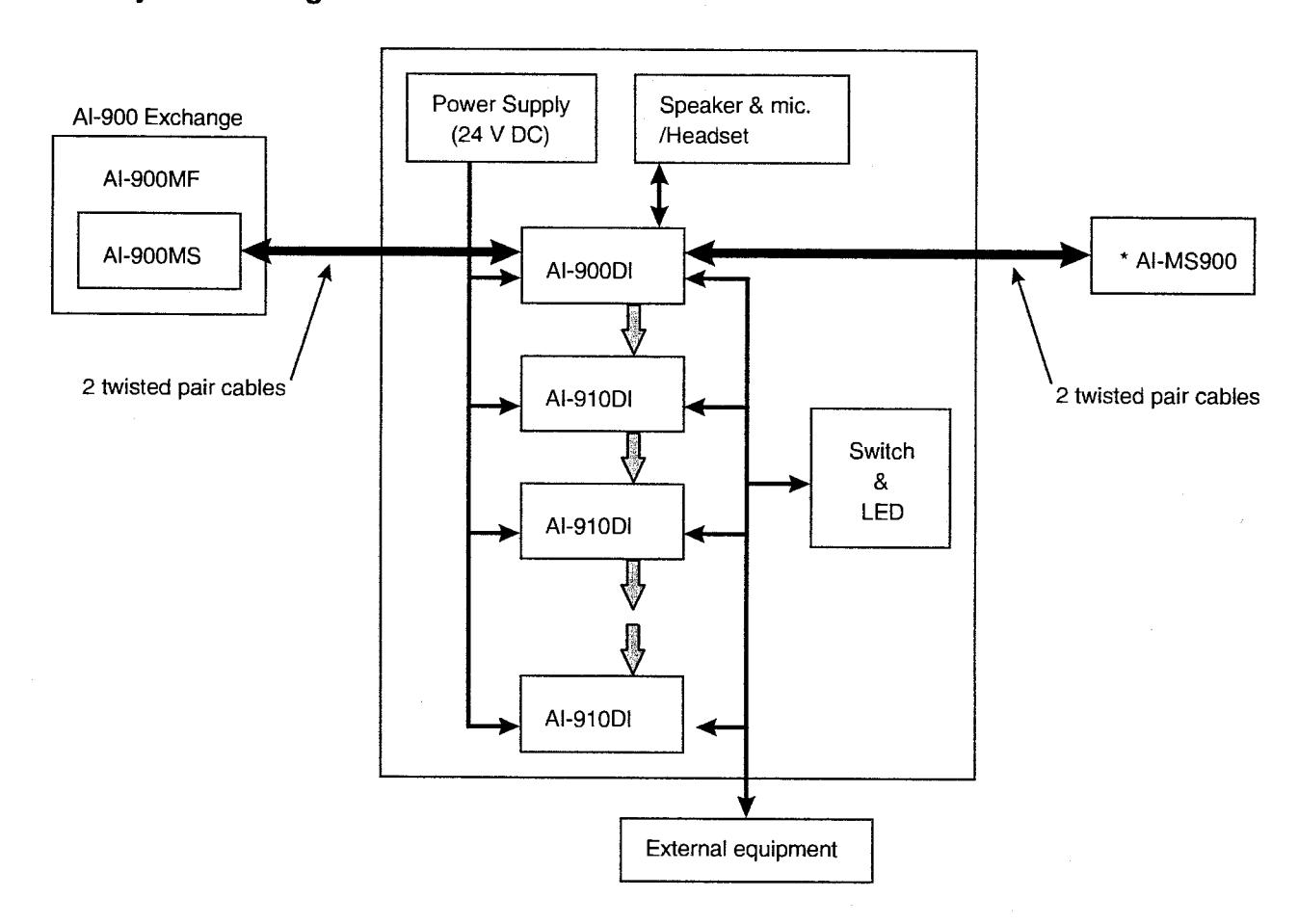
* A call can be enabled using the AI-MS900 Master Station.
2.2. Basic Operation
The AI-900DI Direct Select Control Card transmits, instead of the AI-MS900 Master Station, dial signals corresponding to key inputs. Based on information provided by the AI-900 Exchange, the AI-900DI also outputs signals for the calling station indication and external equipment control to the AI-910DI Direct Select I/O Card, which in turn controls LEDs, switches and external equipment.
Block Diagram
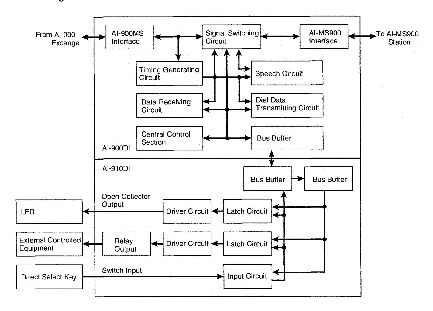
Note
For the functions of the LED drive output, relay output, and switch input, refer to p. 24 "FUNCTIONS AND OPERATION."
3. NOMENCLATURE AND DIMENSIONAL DIAGRAM
[Direct select control card Al-900Dl]
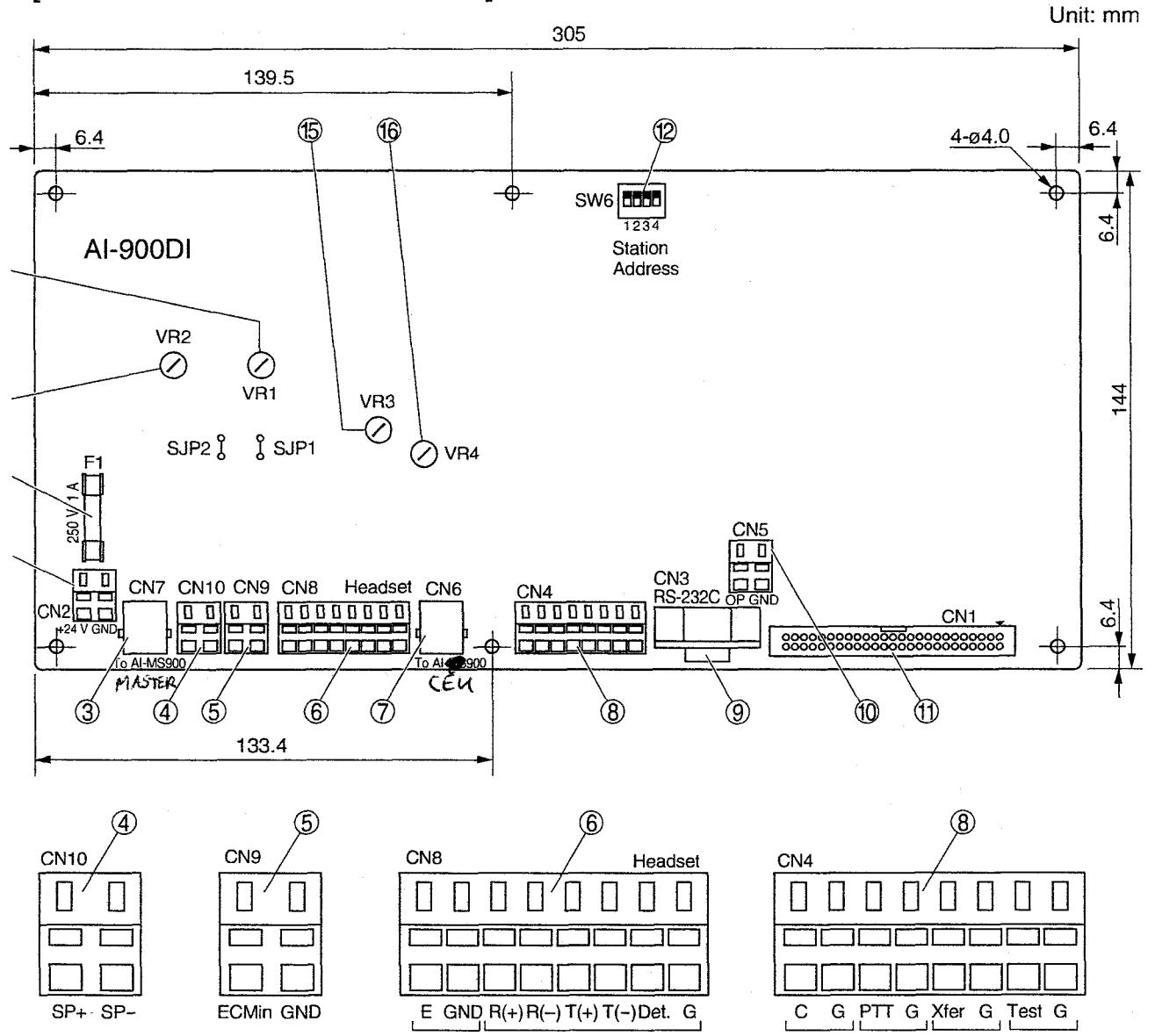
1. Fuse (250 V, 1 A) [F1]
Protects the equipment from major electrical damage.
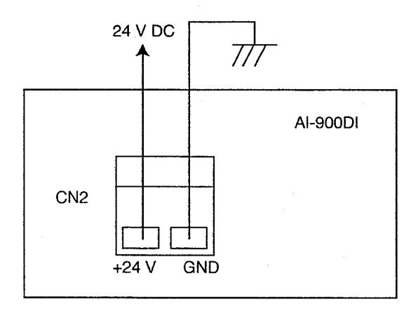
2. 24 V DC power supply terminal [CN2]
Connects to the power supply for internal circuit operation.
3. Modular jack for Al-MS900 [CN7]
Connects to the master station.
4. Speaker output terminal [CN10]
Connects to an external speaker for voice amplification when using the speech function.
5. Electret microphone input terminal [CN9]
Connects to a hands-free microphone when using the speech function.
(Phantom power is fed to this terminal with the jumper SJP2 connected.)
6. Headset and Earth/GND terminal [CN8]
Connects to a headset when using the speech function by way of the headset. Connect Terminal E to the earth ground.
7. Modular jack for Al-900 [CN6]
Connects to the AI-900MS mounted in the AI-900 exchange.
8. Key input terminal [CN4]
Connects to the keys that correspond to the master station's [C], [PTT], and [XFER] keys, and the [Test] key.
9. RS-232C D-sub type connector (female type) [CN31
Used to program data corresponding to each AI-900Dlis terminal.
10. In-use indication output terminal [CN5]
An open collector output that transmits "make" signals while the AI-900DI is in use.
11. Connector for AI-91 OD1 card [CNl]
Connects to the AI-91 ODI.
12. Station address setting switch [SWG]
Sets the station address number depending on the line connecting the AI-900DI.
13. Headset microphone sensitivity control [VRI]
A semi-fixed volume control used to adjust headset microphone sensitivity.
14. Microphone sensitivity control [VR2]
(for the microphone connected to CN9) A semi-fixed volume control used to adjust hands-free microphone sensitivity.
15. Headset speaker volume control [VR3]
A semi-fixed volume control used to adjust headset receiver volume.
16. Speaker volume control [VR4]
(for the speaker connected to CN10) A semi-fixed volume control used to adjust hands-free speaker volume.
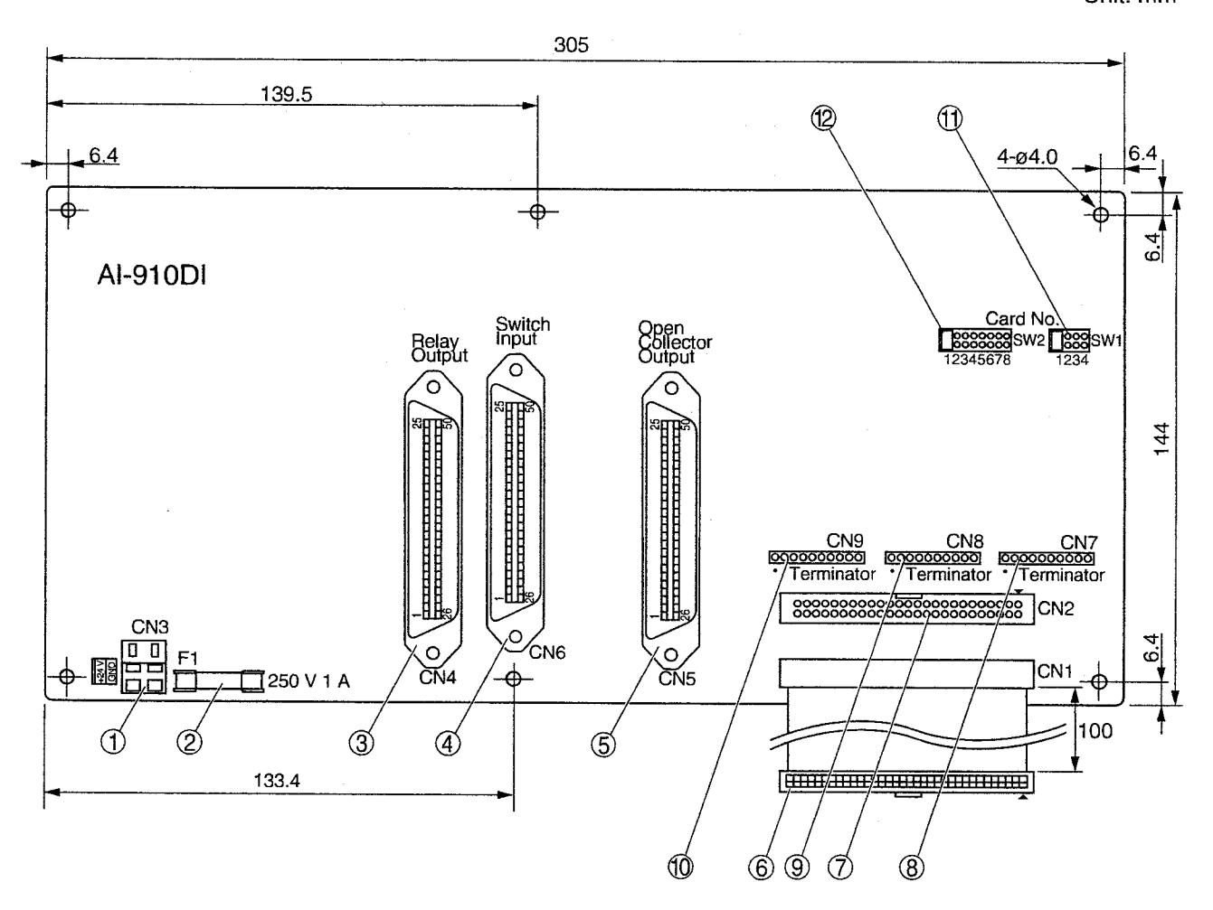
1.24 V DC power supply terminal [CN3]
Connects to the power supply for internal circuit operation.
2. Fuse (250 V, 1 A) [Fl]
Protects the equipment from major electrical damage.
3. Relay output connector ("CHAMP 8" IDC connector 50P) [CN4]
Used when interlocking external equipment.
4. Switch input connector ("CHAMP 8" IDC connector 50P) [CNG]
A key entry terminal for Direct Select. Pressing the key connects the call to the station programmed into that key.
5. Open collector output connector ("CHAMP 8" IDC connector 50P) [CN5]
An open collector output for callinglcalled station indication. The indication flashes or continuously lights depending on call reception conditions.
6. Cable connector for AI-900DI or AI-910DI card [CNI]
Connects the AI-900DI or AI-91 ODI, and permits connection of up to 32 AI-910DI cards.
7. Connector for AI-91 OD1 card expansion [CN2] Connects 2 or more AI-910DI cards to the AI-900DI. Connect the second AI-91 ODl's cable connector (No. 6) to the first card's [CN2]
connector.
8. Terminator [CN7]
9. Terminator [CN8]
10. Terminator [CNS]
Terminating resistor connectors.
When using 2 or more AI-910DI cards, remove terminator resistors of all connected AI-91 OD1 cards except that located farthest from the AI-900DI card.
11. Card number setting switch [SWl]
12. Card number setting switch [SWP]
Sets the AI-910DI card number.
4. SYSTEM DESIGN
Prepare the required equipment according to the procedures below.
- Step 1. Determine the required number of LEDs, switches, and interlocking devices.
- Step 2. Determine whether or not the Al-900Dl's talk function will be used. If this card function is not used, use the Al-MS900 Master Station for conversation.
- Step 3. Determine the number of Al-910DI cards required based on the result of Step 1 above.
Tip
The Al-910DI Direct Select I/O Card has 32 calling station indication outputs, 32 direct select inputs, and 32 external device control outputs.
Step 4. Determine the power capacity required, and prepare the power supply. Be sure to provide sufficient power capacity for external parts such as LEDs, in addition to the current consumed by each card.
5. INSTALLATION
5.1. Setting the Al-900DI Station Addresses
Settings are required for both the station address and whether or not the talk function will be used. If the talk function is not used, use the AI-MS900 for conversation. Perform the following setting using switch SW6.
Note
If the SW6 setting has been changed, turn OFF the unit power, then ON again.
| AI-900MS | Line number | Station address | Not using the Al-MS900 | Using the Al-MS900 |
|---|---|---|---|---|
| MS/AL slot 1 | 1 | 1 | ON OFF 1 2 3 4 | ON OFF 1 2 3 4 |
| WIS/AL SIUL I | 2 | 2 | ON OFF 1 2 3 4 | ON OFF 1 2 3 4 |
| MS/AL slot 2 | 1 | 3 | ON OFF 1 2 3 4 | ON OFF 1 2 3 4 |
| Wien E dot 2 | 2 | 4 | ON OFF 1 2 3 4 | ON OFF 1 2 3 4 |
5.2. Setting the AI-910DI Card Numbers
The number of the card to be used for the AI-910DI needs to be set. Perform the following setting using
|
Al-910DI
Card No. |
SW1 | SW2 |
Al-910DI
Card No. |
SW1 | SW2 |
Al-910DI
Card No. |
SW1 | SW2 |
Al-910Dl
Card No. |
SW1 | SW2 |
|---|---|---|---|---|---|---|---|---|---|---|---|
| 1 | 1234 | 12345678 | 9 | 1 2 3 4 | 12345678 | 17 | 1234 | 12345678 | 25 | 0 0 0 0 0 0 0 0 0 0 0 0 0 0 0 0 0 0 0 0 | 12345678 |
| 2 | 1234 | 12345678 | 10 |
0 0 0
0 0 0 1 2 3 4 |
12345678 | 18 |
0 0 0 0
0 0 0 1 2 3 4 |
12345678 | 26 | 1 2 3 4 | 12345678 |
| 3 | 1234 | 12345678 | 11 | 1 2 3 4 | 12345678 | 19 |
0 0 0
0 0 0 1 2 3 4 |
12345678 | 27 | 1 2 3 4 | 12345678 |
| 4 | 1 2 3 4 | 12345678 | 12 | 1 2 3 4 | 12345678 | 20 | 1234 | 12345678 | 28 | 1 2 3 4 | 12345678 |
| 5 | 1234 | 12345678 | 13 | 1234 | 12345678 | 21 | 1 2 3 4 | 12345678 | 29 | 1 2 3 4 | 0000 000 |
| 6 | 1234 | 12345678 | 14 |
0 0 0
0 0 0 1 2 3 4 |
12345678 | 22 | 1 2 3 4 | 12345678 | 30 | 1234 | 12345678 |
| 7 | 1 2 3 4 | 12345678 | 15 | 1 2 3 4 | 12345678 | 23 | 1 2 3 4 | 12345678 | 31 | 1 2 3 4 | 12345678 |
| 8 | 1 2 3 4 | 12345678 | 16 |
0 0 0
0 0 0 1 2 3 4 |
12345678 | 24 | 0 0 0 0 0 1 2 3 4 | 12345678 | 32 | 1234 | 12345678 |
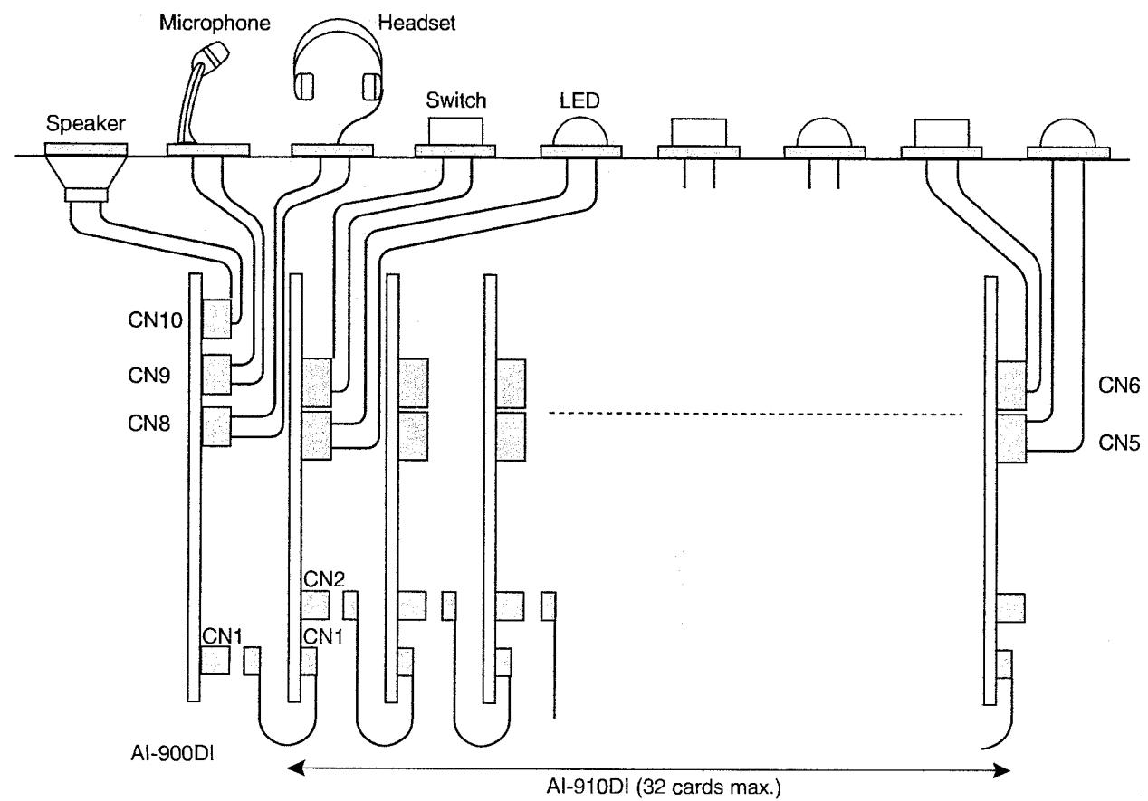
5.3. Installing The AI-900DIlAI-91 OD1
Connect each card as illustrated below.
When connecting 2 or more AI-910DI cards, remove the terminating resistors in CN7, CN8, and CN9, except the AI-910DI card farthest from the AI-900DI card.
For the interlocking outputs to the LED, switch, or external equipment, connect them after completing all connections as shown below.
5.4. AI-900DI Connection
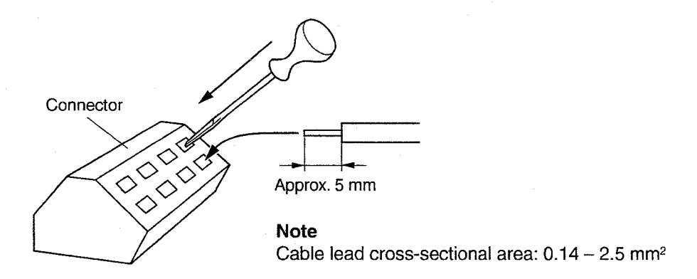
5.4.1. Connector connection
- Step 1. Strip the end of the cable back approximately 5 mm.
- Step 2. While pressing on the upper side of the connector with a standard screwdriver as shown in the figure, insert the cable leads.
5.4.2. CN2 power supply terminal connection
5.4.3. Connection to the exchange
-
Connect the AI-900DI to the AI-900MS using 2 twisted pair cables as shown below referring to the folic procedures.
- 1. Fit the 4P connector (supplied with the AI-900MS) to one cable end, and a 6-position 4-contact mo jack (prepare locally) to the other cable end.
- 2. Connect the modular jack to the Al-900DI's CN6 modular jack using the modular cord (supplied wit Al-900DI).
- The table below shows the maximum cable distance.
| Cable type | AWG24 (0.52 mm) | AWG22 (0.65 mm) | AWG20 (0.82 mm) |
|---|---|---|---|
| Distance | 0.9 km | 1.5 km | 2.3 km |
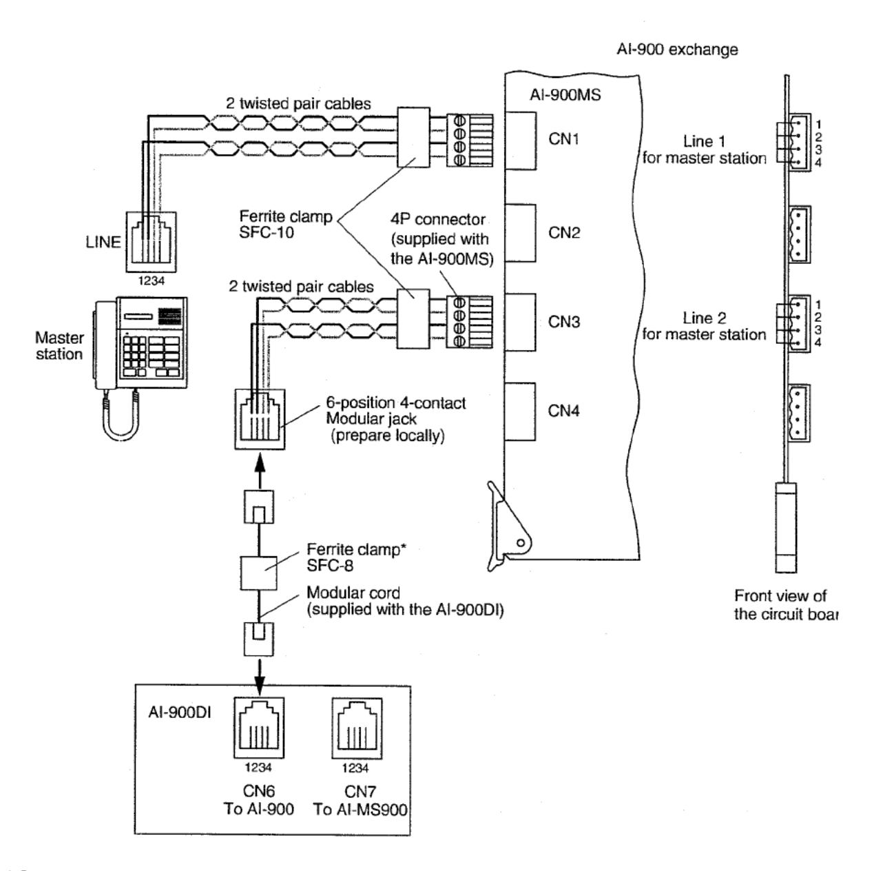
* See p.13 "Mounting the ferrite clamp."
5.4.4. Connection to the Al-MS900 Master Station
-
••Connect the Al-900DI to the Al-MS900 using 2 twisted pair cables as shown below referring to the following procedures.
- 1. Fit a 6-position 4-contact modular jack (prepare locally) to each cable end.
- 2. Connect one modular jack to the Al-900DI's CN7 modular jack using the modular cord (prepare locally), and another jack to the Al-MS900 modular jack using a modular cable (supplied with the Al-MS900).
- ••When using the Master Station, the maximum cable distance is the total connected distance from the exchange to the Master Station via the Al-900DI.
| Cable type | AWG24 (0.52 mm) | AWG22 (0.65 mm) | AWG20 (0.82 mm) |
|---|---|---|---|
| Distance | 0.9 km | 1.5 km | 2.3 km |
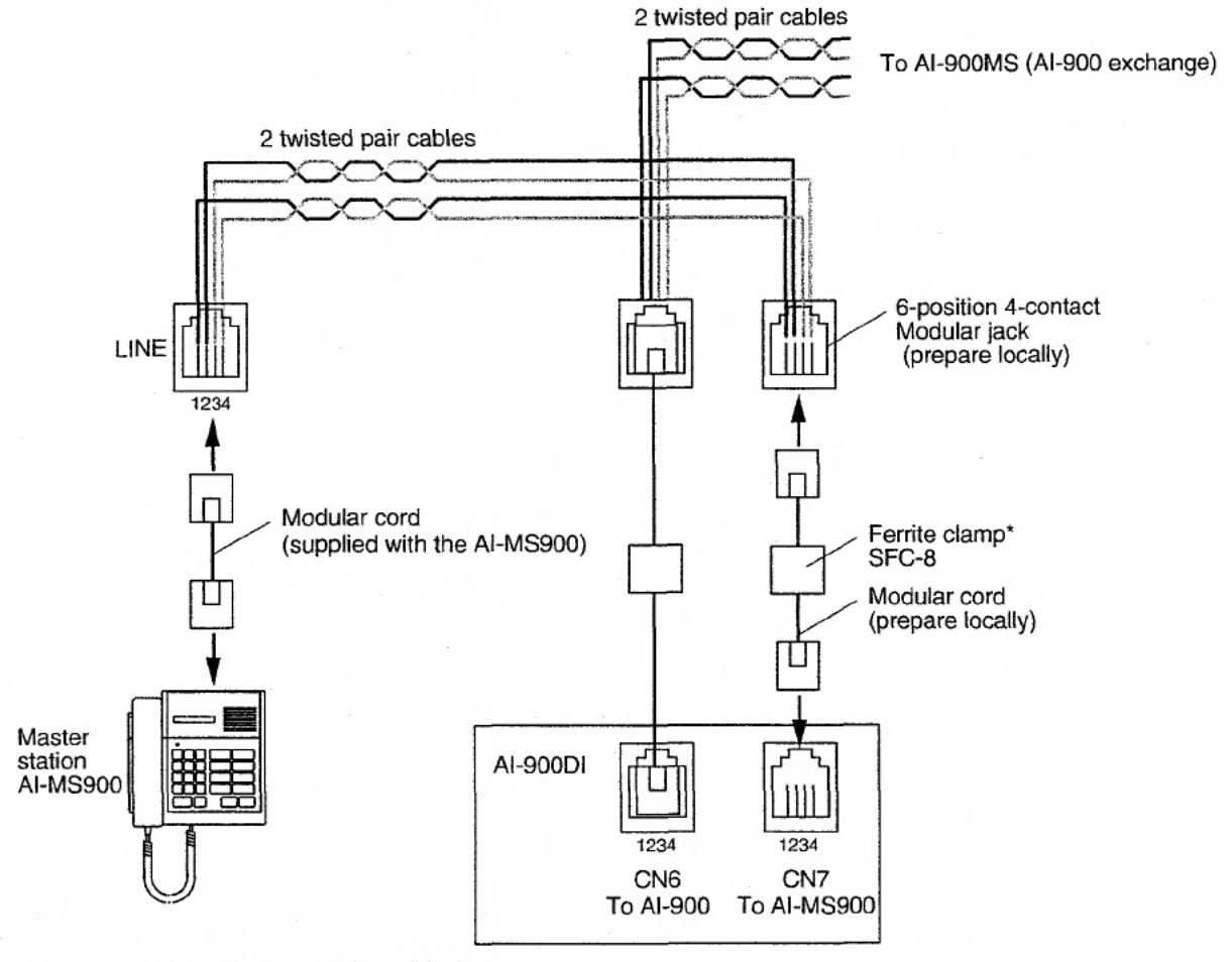
* See "Mounting the ferrite clamp" below.
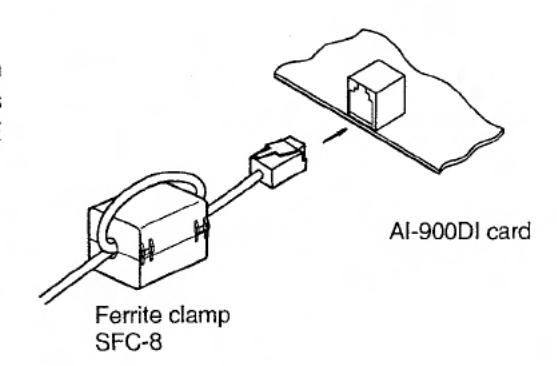
5.4.5. Mounting the ferrite clamp
Mount the ferrite clamp (supplied with the AI-900DI card) on the cable in a way that the cable is looped one turn as illustrated. (This countermeasure is for complying with the CE marking and FCC requirements.)
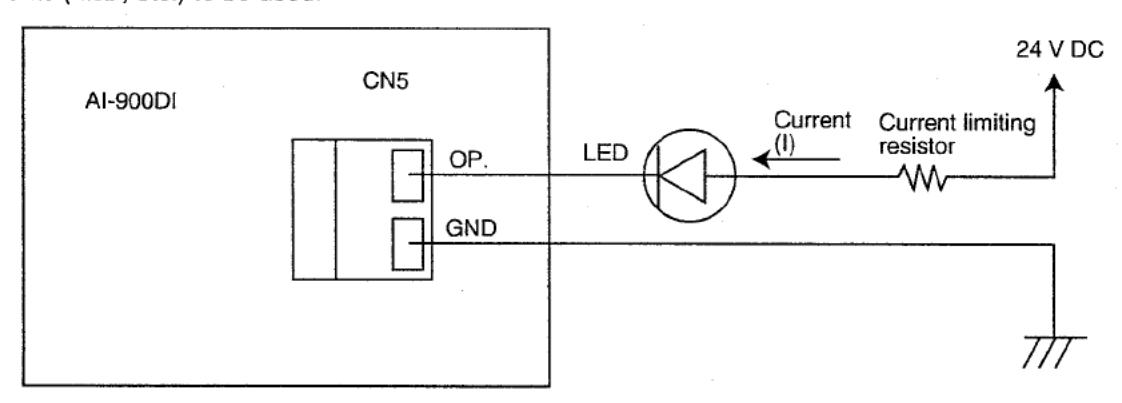
5.4.6. CN5 in-use indication output connection
- Connect the in-use indication output to the LED from the CN5 connector as shown below.
- A current capacity of 24 V DC/100 mA is required per output.
- To use an LED, connect a current limiting resistor in series with it as the resistor is not built in the card.
- Determine the appropriate resistor value depending on the amount of current (I) necessary for indication elements (LED, etc.) to be used.
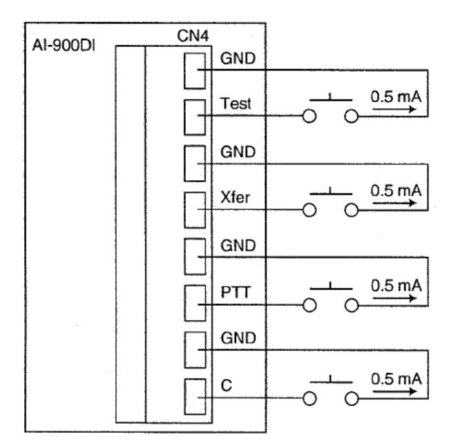
5.4.7. CN4 Input key (C/PTT/XFER/Test key) connection
Connect the input key to the switches from the CN4 connector as shown below. Each contact carries a current of 0.5 mA.
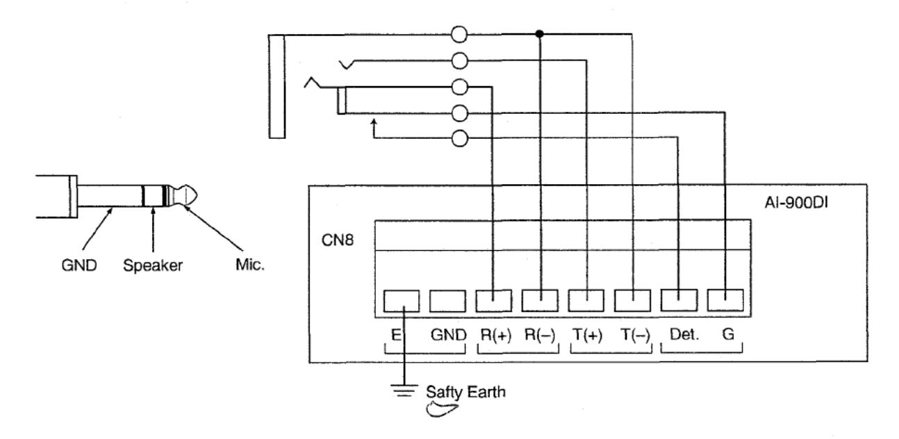
5.4.8. CN8 headset connection
- ◆Use the headset with microphone sensitivity of -75 to -65 dB and speaker impedance of 200 to 400 Ω.
- •Whether to insert a headset for response or to add a switch for response can be selected at the time of connection. The connection is as follows.
- If adding the switch, use the devices connected to CN8's Det. And G terminals as switches.
- If the headset microphone is of dynamic type, cut the jumper SJP1.
- -Adjust the semi-fixed control VR1 for optimum microphone sensitivity.
- Adjust the semi-fixed control VR3 for optimum speaker sound volume.
5.4.9. Earth grounded connection
Be sure to connect the earth ground from E terminal of CN8 screwless terminal as illustrated above.
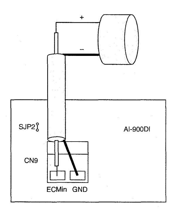
5.4.10. CN9 microphone input connection
Use an electret microphone, and shielded cables for its wiring. Pay attention to the polarity, and be sure to connect the signal side (+) to the ~~dn terminal. I
Note
Cut the jumper SJP2 on the AI-900DI card when using a dynamic microphone or externally-powered microphone. (This work results in cutting off the phantom power supply.) Adjust the semi-fixed control VR2 for optimum microphone sensitivity.
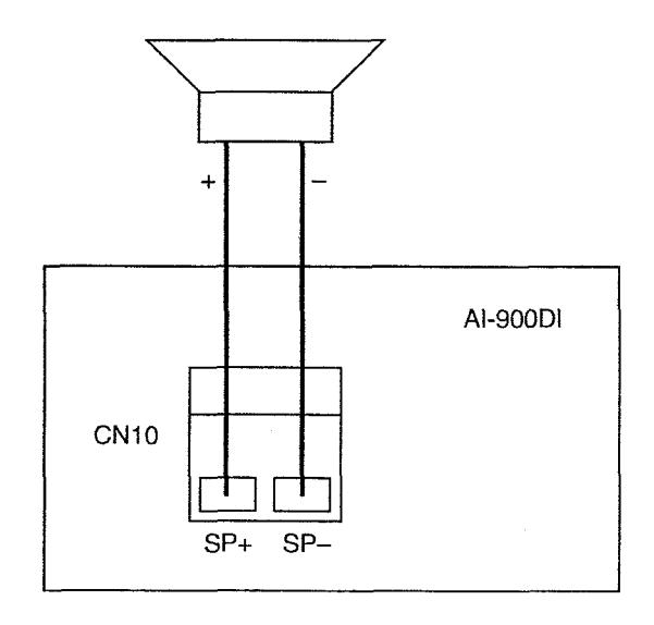
5.4.1 1. CN10 speaker output connection
Be sure to use the speaker with impedance of 8 Q. Power output derived from the card is 1 W maximum. Adjust the semi-fixed control VR4 for optimum speaker sound volume.
5.5. AI-910DI Connection
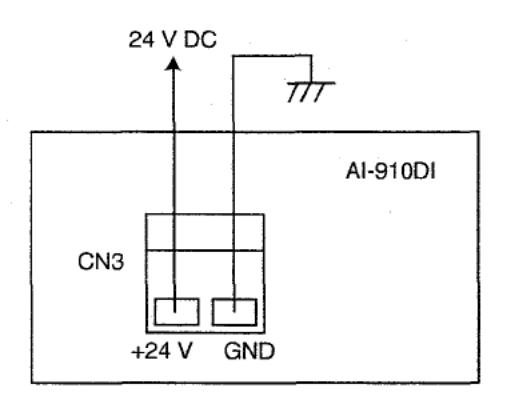
5.5.1. CN3 power supply terminal connection
5.5.2. Calling station indication output connection
-
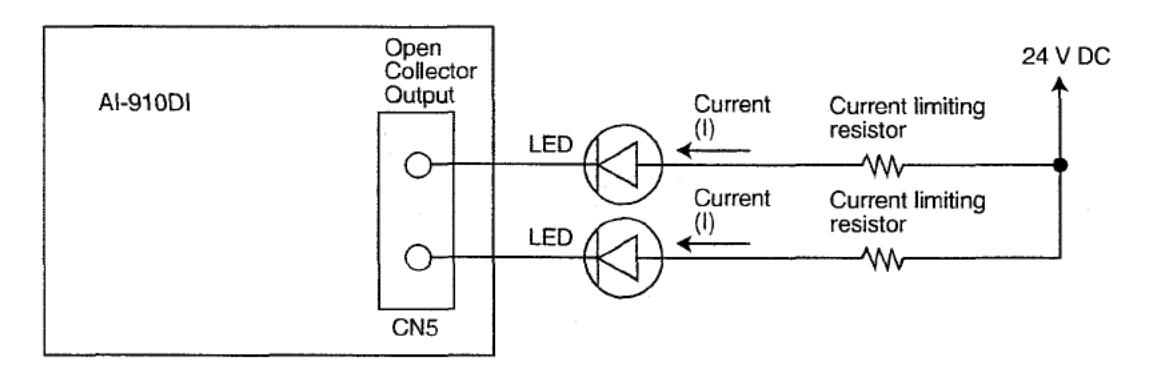
The calling station indication output is connected to the LED from the 50-position Miniature Ribbon Plug* of CN5 according to the figure below. For the relationship between the CN5 connector pins and their corresponding outputs, refer to the table below.
- * Equivalent to "CHAMP ®" IDC type (Amphenol type)
- Each output requires a current capacity of 24 V DC/100 mA.
- To use an LED, connect a current limiting resistor in series with it as the resistor is not build in the card.
- Determine the appropriate resistor value depending on the amount of current (I) necessary for indication elements (LED, etc.) to be used.
|
CALL-IN
LED No. |
Connector
Pin No. |
CALL-IN
LED No. |
Connector
Pin No. |
CALL-IN
LED No. |
Connector
Pin No. |
CALL-IN
LED No. |
Connector
Pin No. |
|---|---|---|---|---|---|---|---|
| 1 | CN5-1 | 9 | CN5-9 | 17 | CN5-17 | 25 | CN5-25 |
| 2 | CN5-2 | 10 | CN5-10 | 18 | CN5-18 | 26 | CN5-26 |
| 3 | CN5-3 | 11 | CN5-11 | 19 | CN5-19 | 27 | CN5-27 |
| 4 | CN5-4 | 12 | CN5-12 | 20 | CN5-20 | 28 | CN5-28 |
| 5 | CN5-5 | 13 | CN5-13 | 21 | CN5-21 | 29 | CN5-29 |
| 6 | CN5-6 | 14 | CN5-14 | 22 | CN5-22 | 30 | CN5-30 |
| 7 | CN5-7 | 15 | CN5-15 | 23 | CN5-23 | 31 | CN5-31 |
| 8 | CN5-8 | 16 | CN5-16 | 24 | CN5-24 | 32 | CN5-32 |
| GND |
CN5-33 to
CN5-50 |
5.5.3. Direct select input connection
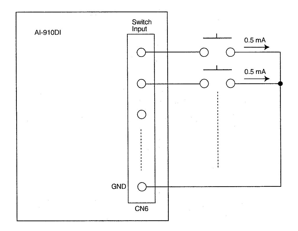
Connect the direct select input from CN6's 50-position Miniature Ribbon Plug* as shown below. For the relationship between the CN6 connector pins and their corresponding inputs, refer to the table below. Each contact carries a current of 0.5 mA.
* Equivalent to "CHAMP ®" IDC type (Amphenol type)
|
SELECT SW
No. |
Connector
Pin No. |
SELECT SW
No. |
Connector
Pin No. |
SELECT SW
No. |
Connector
Pin No. |
SELECT SW
No. |
Connector
Pin No. |
|---|---|---|---|---|---|---|---|
| 1 | CN6-1 | 9 | CN6-9 | 17 | CN6-17 | 25 | CN6-25 |
| 2 | CN6-2 | 10 | CN6-10 | 18 | CN6-18 | 26 | CN6-26 |
| 3 | CN6-3 | 11 | CN6-11 | 19 | CN6-19 | 27 | CN6-27 |
| 4 | CN6-4 | 12 | CN6-12 | 20 | CN6-20 | 28 | CN6-28 |
| 5 | CN6-5 | 13 | CN6-13 | 21 | CN6-21 | 29 | CN6-29 |
| 6 | CN6-6 | 14 | CN6-14 | 22 | CN6-22 | 30 | CN6-30 |
| 7 | CN6-7 | 15 | CN6-15 | 23 | CN6-23 | 31 | CN6-31 |
| 8 | CN6-8 | 16 | CN6-16 | 24 | CN6-24 | 32 | CN6-32 |
| GND |
CN6-33 to
CN6-50 |
||||||
5.5.4. External equipment control output connection
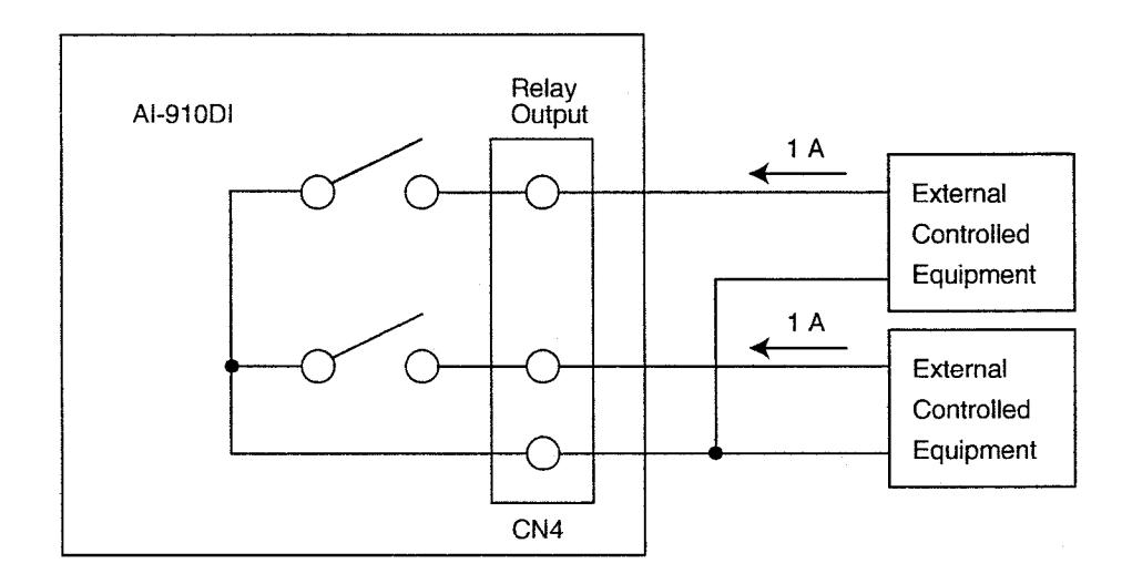
Connect the external equipment control output to the equipment to be controlled from CN4's 50-position Miniature Ribbon Plug* as shown below. For the relationship between the CN4 connector pins and their corresponding inputs, refer to the following table.
The contact capacity is 24 V DC/1 A.
* Equivalent to "CHAMP ®" IDC type (Amphenol type)
|
CONTROL
OUTPUT No. |
Connector
Pin No. |
CONTROL
OUTPUT No. |
Connector
Pin No. |
CONTROL
OUTPUT No. |
Connector
Pin No. |
CONTROL
OUTPUT No. |
Connector
Pin No. |
|---|---|---|---|---|---|---|---|
| 1 | CN4-1 | 9 | CN4-9 | 17 | CN4-17 | 25 | CN4-25 |
| 2 | CN4-2 | 10 | CN4-10 | 18 | CN4-18 | 26 | CN4-26 |
| 3 | CN4-3 | 11 | CN4-11 | 19 | CN4-19 | 27 | CN4-27 |
| 4 | CN4-4 | 12 | CN4-12 | 20 | CN4-20 | 28 | CN4-28 |
| 5 | CN4-5 | 13 | CN4-13 | 21 | CN4-21 | 29 | CN4-29 |
| 6 | CN4-6 | 14 | CN4-14 | 22 | CN4-22 | 30 | CN4-30 |
| 7 | CN4-7 | 15 | CN4-15 | 23 | CN4-23 | 31 | CN4-31 |
| 8 | CN4-8 | 16 | CN4-16 | 24 | CN4-24 | 32 | CN4-32 |
| COMMON |
CN4-33 to
CN4-50 |
5.5.5. AI-91 ODl's CN4lCN51CN6 connections
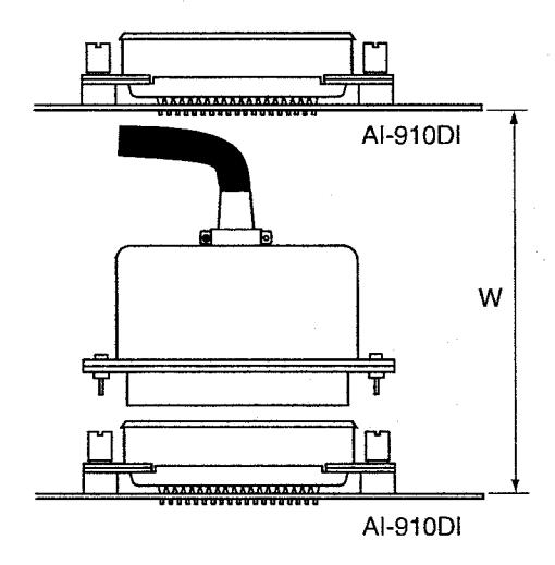
Use a 50-position Miniature Ribbon Jack*' for connecting CN4lCN51CN6 of the AI-910DI card. The size of the plug on the circuit board side is as illustrated below.
The size of the plug on the AI-91 OD1 card
Unit: mm
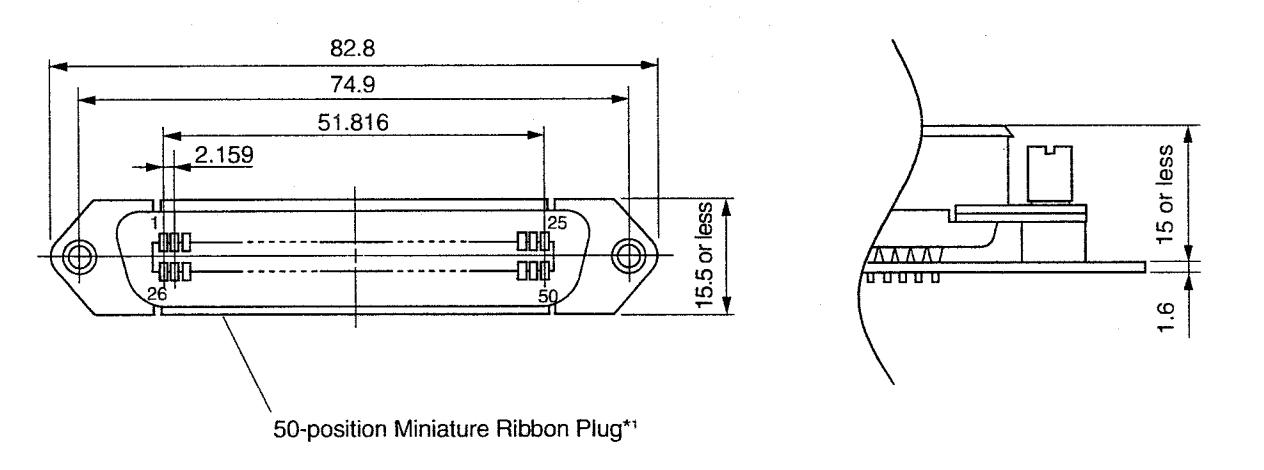
Depending upon the type of connector to be used, the space (W*2) between circuit boards needs to be determined.
- *l Equivalent to "CHAMP 8" IDC type (Amphenol type)
- *2 The maximum length W is 10 cm due to the limited length of a ribbon cable connecting between boards.
6. REGISTRATION
Use the Al-900 PC interface software to register the station No. for each key input.
6.1. Direct Select Setting
Connect the AI-900DI to the AI-900MF for setting. Designate the exchange number, then perform the following settings:
| Setting Item | Contents | ||||
|---|---|---|---|---|---|
| Control output mode | Select the external equipment control output operation mode. Response-Activate: Make contact when conversation begins. Call-Activated: Make output when calls are initiated. | ||||
6.2. Direct Select Dial Setting
Connect the Al-900DI to other Al-900DI.
Designate both the exchange number and the master station address, then perform the following settings:
| Setting Item | Contents |
|---|---|
| One-shot make duration | Set the one-shot make duration. |
| Dial number | Set the number to be programmed into each key. (If the station number is assigned to the dial number, the name programmed during exchange line setting is displayed in the "Name" item.) |
| Remote door control output number (Switch number) | Set the output number to be used in remote door control. |
6.3. Programming PC Connection
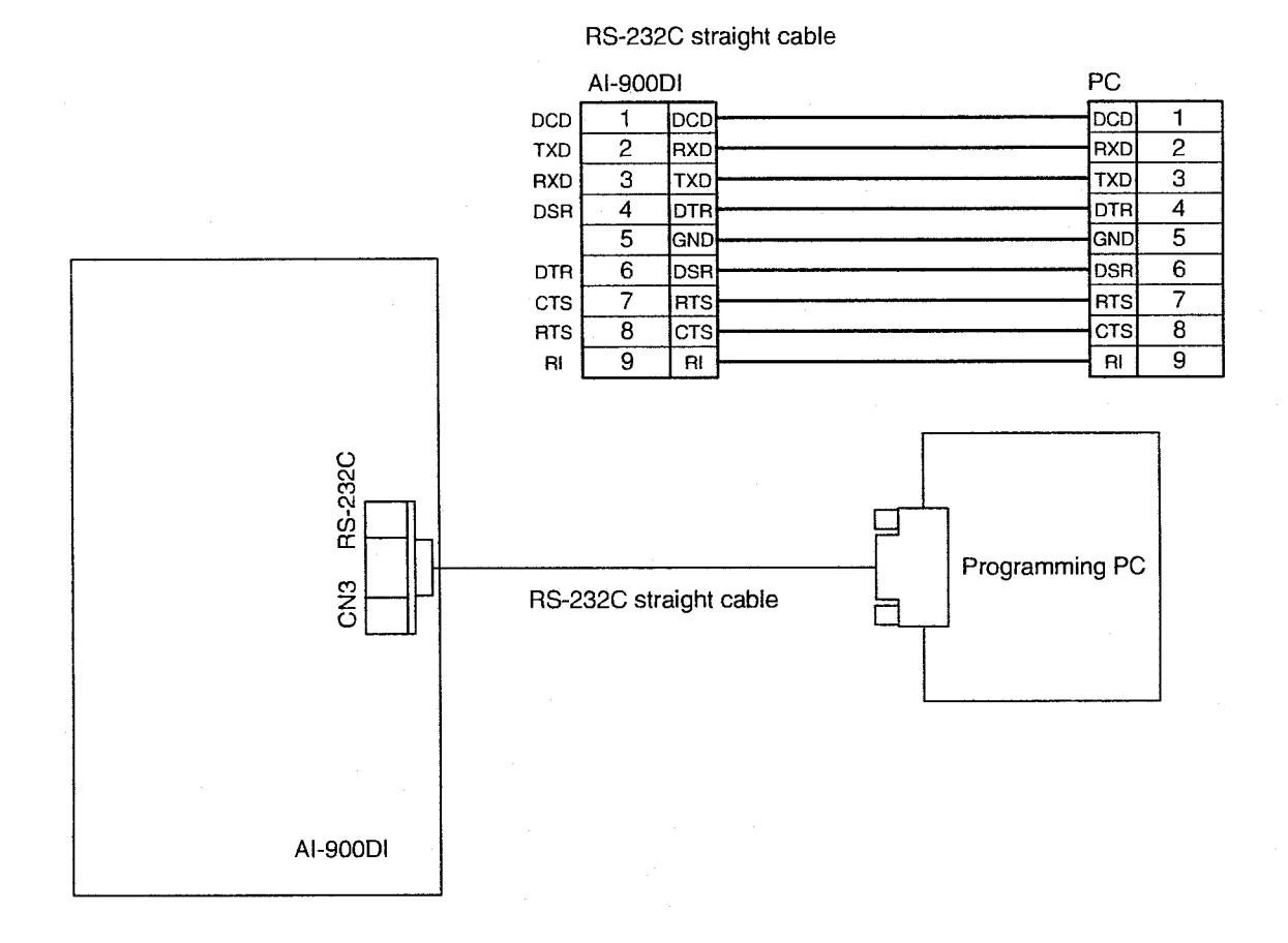
Connect the Al-900DI to the programming PC by using an RS-232C cable as shown below.
6.4. Programming Data Entry
6.4.1. Entry when the Al-900Dl alone is used
Switch on the AI-900DI's power.
Enter the set data. Do not switch off the power until LEDs 1 to 8 begin to flash, which indicates data registration completion.
6.4.2. Entry when the Al-900DI is connected to the Al-910DI
Switch on the power after checking for proper connections between the two cards, then enter the set data. Do not switch off power until LEDs 1 to 8 begin to flash, which indicates data registration completion.
7. OPERATION TEST
7.1. Operation Check by Means of the Test Switch
Using the test switch, operations of both the calling station indication output and external equipment control output can be checked.
- Step 1. Push CN4's test key without connecting the card to the exchange, and enter test mode.
- Step 2. Turn on and off indication outputs 1-32 and control outputs 1-32 on Card No. 1 first, and then check outputs 1-32 on Card No. 2 by turning them on and off. Similarly, repeat the same tests for up to Card No. 32.
- Step 3. To quit$ the test mode, turn the power off, then turn it on again.
7.2. Check through Individual Operations
7.2.1. Checking AI-900DI/AI-910DI for proper operation without using the master station
- Step 1. Connect the AI-900DI to the exchange.
-
Step
2. Dial with the direct select selection input to call the person you want to talk to.
- *The LED connected to the calling station indication output lights, permitting synchronized operation of the devices connected to the external equipment control output.
- *incoming calls can be responded to by means of the Direct Select input corresponding to the receiving indication. As in the above case, the LED connected to the calling station indication output also lights, permitting synchronized operation of the devices connected to the external equipment control output.
[Conversation through the Headset]
Connect the phone jack to the AI-900DI referring to p. 15 "CN8 headset connection."
- Step 3. Connect the headset plug into the jack, and conversation can be made using the headset. The conversation type of "Duplex", "Press-to-talk", or "Voice-operated switching" depends on other party's type of unit and conversation mode.
- Step 4. Press [C] key to terminate conversation.
[Conversation through the Microphone and Speaker]
Do not connect the headset.
- Step 3. Conversation can be made using the microphone and speaker. The conversation type of "Duplex", "Press-to-talk", or "Voice-operated switching" depends on other party's type of unit and conversation mode.
- Step 4. Press [C] key to terminate conversation.
7.2.2. Checking AI-900DUAI-91 OD1 for proper operation when using the master station
Here check the operation when only their Direct Select functions are used in combination with the master station (case when the master station is used for conversation).
- Step 1. Connect the master station in series with the exchange.
- Step 2. Using the Direct Select Input, dial to make a call, and converse with the connected party through the master station or instead of doing this, dial at the master station and converse with the connected party. The LED connected to the calling station indication output lights, permitting synchronized operation of the devices connected to the external equipment control output. Also, incoming calls can be responded to by means of the Direct Select input corresponding to the receiving indication. As in the above case, the LED connected to the calling station indication output also lights, permitting synchronized operation of the devices connected to the external equipment control output.
- Step 3. The conversation can be terminated by means of on-hook operation or the [C] key on the master station or AI-900Dl's input key or CN4's [C] key.
Tip
The call transfer function can also be used by means of the AI-900Dl's transfer key (CN4's [Xfer] key).
8. FUNCTIONS AND OPERATION
8.1. Calling/Called Station lndication Output
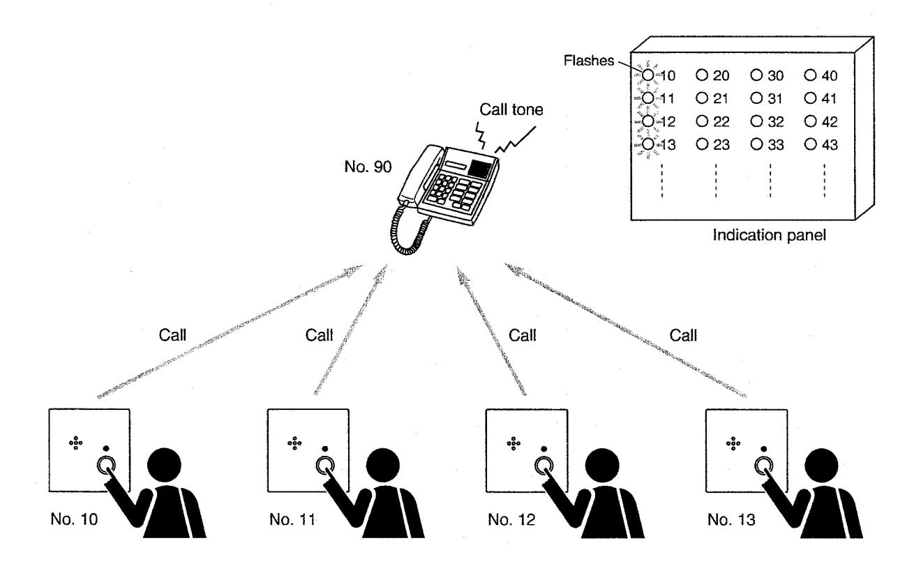
Calling and called parties can be indicated on the corresponding LED indicators by making the LED indicators on the indicator panel that correspond to the stations for each master station.
- 1. Emergency station making a call: Quick flashes
- 2. Normal station making a call: Slow flashes
- 3. Station being called: Continuously lit
- 4. Conversation partner station: Continuously lit.
- 5. Station placed on hold: Continuously lit.
- 6. Station being scan-monitored: Continuously lit
- 7. Station under any other than the above conditions: Extinguished.
[System pre-programming]
To use the indication function, both the calling/called indication output and dial operation must be assigned by system programming.
8.2. Direct Select Input
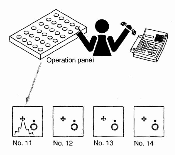
If an operation panel containing switches corresponding to the stations is prepared for each master station, a desired party can be called or a calling party can be responded to by simply pressing the corresponding switch.
[System pre-programming]
To use the above function, both the Direct Select input switch and dial operation must be assigned and programmed by system programming.
8.3. External Equipment Control Output
Connected external equipment can be controlled using the following 2 types of timings by making the control panel providing relay outputs that correspond to the stations for each master station.
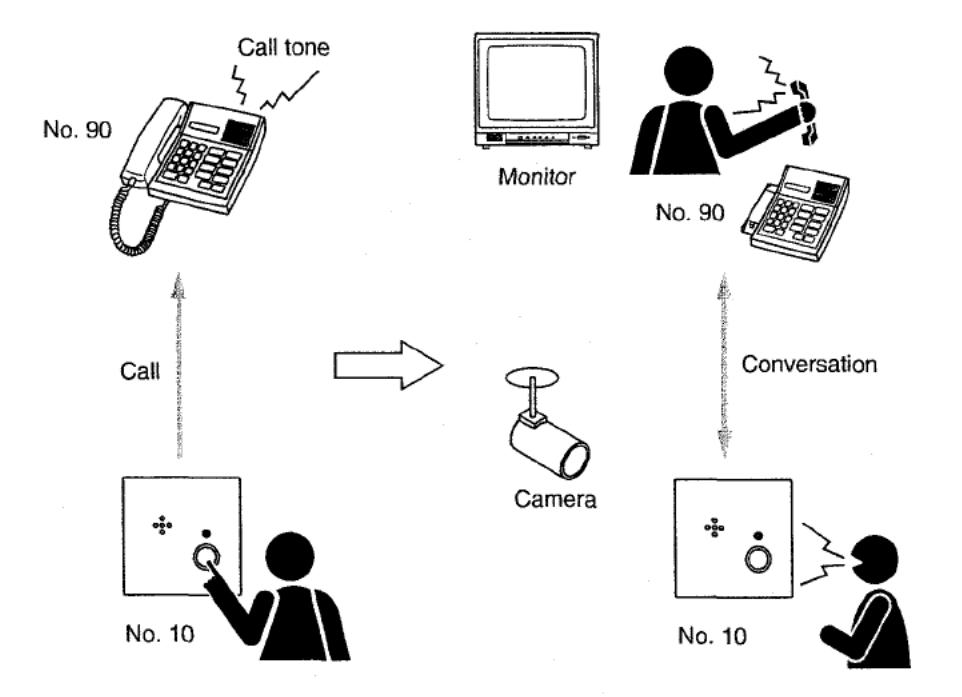
8.3.1. CCTV interlock output
Contact points corresponding to the stations open and close in synchronization with operations such as calls from other station or conversation commencement. (For example, connection to the surveillance camera system creates a system which interlocks with video image output.)
[System pre-programming]
- To use the above function, both dial operation and external control output must be assigned and programmed by system programming.
- Select [Response-Activate] or [Call-Activated] by system programming as the condition to make the control output using the system programming.
8.3.2. Remote door control output
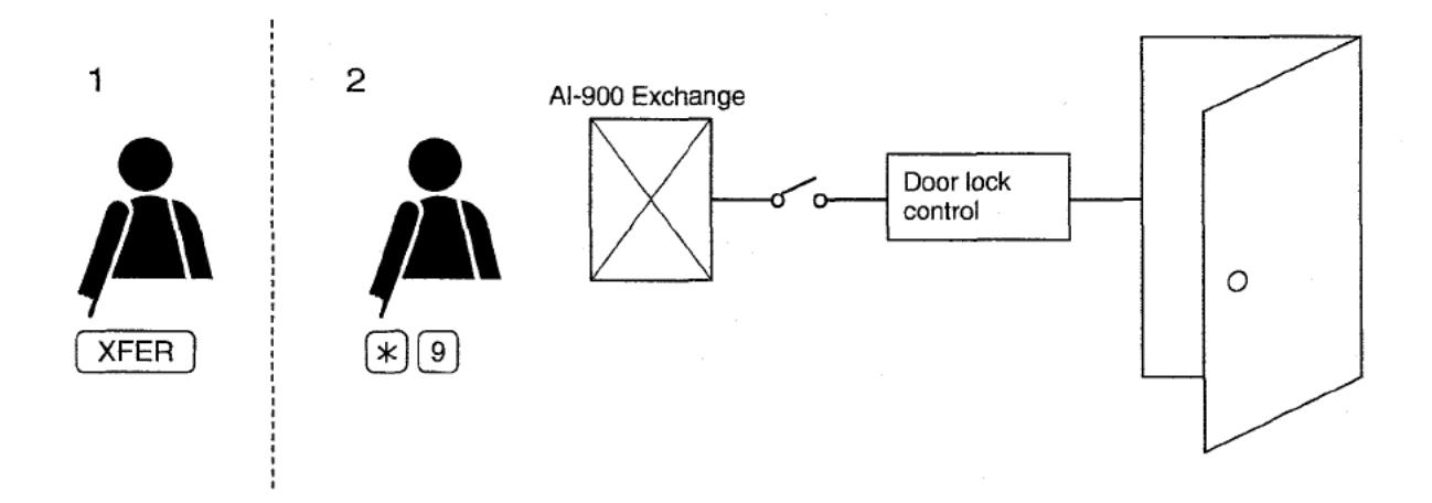
Performing the following operations during conversation with another station makes (closes) the contact point corresponding to the conversation partner's station for a specified period of time. (For example, connection to the electric lock system creates the door lock control system.)
[System pre-programming]
- To use the above function, one-shot make output signals must be programmed by system programming for external control and dial operation assignment.
- The one-shot make duration can be set with the system programming.
[Remote door control operation]
Step 1. Press the [XFER] key during two-party conversations. (In the case of telephones, briefly press the hook switch.)
The current conversation is placed on hold, and a holding tone is transmitted to other party.
Step 2. Press [*] and [9].
The relay corresponding to the conversation partner is closed for a specified period of time. (If connected to the electric lock system, for instance, the corresponding door lock can be released.)
Step 3. A confirmation tone sounds, restoring the original conversation.
8.4. Conversation Using the Master Station
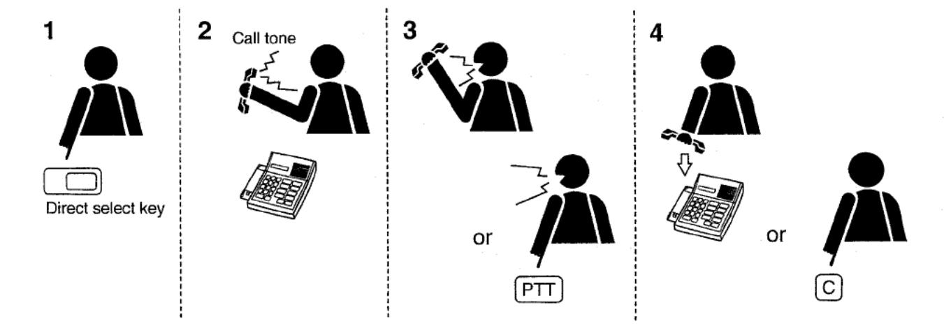
Step 1. Push the switch connected to the Direct Select Input (the "Direct Select Switch") to call the person you want to talk to.
(Dialing can be performed with the handset on-hook or off-hook.)
Step 2. A ringing tone is heard from the master station.
(This tone will be heard from the station's internal speaker if dialed with the handset on-hook.)
Step 3. Talk
Step 4. Replace the handset or push the [C] key to terminate the conversation. (Either the [C] key on the master station or on the Al-900DI can be used.)
8.5. Conversation Using the AI-900DI and Not Using the Master Station
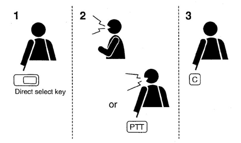
- Step 1. Push the Direct Select Switch to call the person you want to talk to.
- Step 2. Converse using the headset or the loudspeaker and microphone. "Press-to-talk" conversation is also possible by pushing the [PTT] key.
- Step 3. Push the [C] key to terminate the conversation.
Note
Pushing the Direct Select Switch again will not terminate the conversation.
9. SPECIFICATIONS
[AI-900DI]
| Power Source | 24 V DC ±10%/1 A, 2-pole screwless terminal*2 |
| Maximum Cable Length | 1.5 km (including the additional master station line from the AI-900DI) when |
| to Exchange | the cable guage is AWG22 |
| Maximum Number of | 4 cards per exchange, 64 cards per system (16 tie-lined exchanges) |
| Connectable Al-900DI | |
| Cards | |
| Function Key Input | One each of [C], [PTT], [Xfer], and [Test] keys, dry contact, 5 V DC/0.5 mA, |
| contact resistance: 50 Ω or less, 8-pole screwless terminal*2 | |
| Commuication Line | 1 line for AI-900 exchange (AI-900MS card) and 1 line for AI-MS900 master |
| station, 1 6-position/4-contact modular jack for each line | |
| In-use Indication Output | Open collector output, 24 V DC/approx. 100 mA, 2-pole screwless terminal*2 |
| Electret Microphone | Microphone sensitivity: -75 to -65 dB*1, phantom power supply (power supply |
| Input | can be cut off), 2-pole screwless terminal*2 |
| Speaker Output | Speaker impedance: 8 Ω, power output: 1 W maximum, 2-pole screwless |
| terminal*2 | |
| Headset Connection | Microphone sensitivity: to dB*1, speaker impedance: 200 to 400 , |
| detection jack contact input [Det.]: 5 V DC/10 mA, contact resistance: 10 or | |
| less, 8-pole screwless terminal*2 (Headset can also be turned on/off using the | |
| manual switch instead of the jack contact input.) | |
| PC Interface | RS-232C D-sub connector (9 poles, female type) |
0 dB = 1 V(rms)
Bared-core length: 5 – 6 mm
Cross section area: 0.14 - 2.5 mm<sup>2</sup>
Note: The design and specifications are subject to change without notice for improvement.
Accessories
| Ferrite clamp : | SFC-8 | 2 |
|---|---|---|
| Modular cord | (3 m) | 1 |
*2 Usable cable
[AI-910DI]
| Power Source | 24 V DC ±10%/1 A, 2-pole screwless terminal*1 |
| Maximum Number of | 32 |
| Al-910Dls per | |
| Al-900DIs | |
| Maximum Number of | 32 switch inputs (for calling and response switch operation) |
| Ports per Al-910DI | 32 open collector outputs (for LED indication of incoming and outgoing calls) |
| 32 relay outputs (call- or response-activated relay output) | |
| Maximum Number of | 1024 switch inputs (for calling and response switch operation) |
| Ports per Full Al-910DI- | 1024 open collector outputs (for LED indication of incoming and outgoing |
| Mounted System | calls) |
| 1024 relay outputs (call- or response-activated relay output) | |
| Switch Input | 32 inputs (for custom-made direct select key operation for calling or |
| response), dry contact, 5 V DC/0.5 mA, contact resistance: 50 or less, 50- | |
| position Miniature Ribbon Plug*2 | |
| Open Collector Output | 32 outputs (for LED indication of incoming and outgoing calls), 24 V |
| DC/approx. 100 mA, 50-position Miniature Ribbon Plug*2 | |
| Relay Output | 32 relay outputs, call- or response-activated relay output, normal open output, |
| 24 V DC/1 A, 50-position Miniature Ribbon Plug*2 |
*1 Usable cable
Bared-core length: 5 – 6 mm Cross section area: 0.14 – 2.5 mm<sup>2</sup>
Note: The design and specifications are subject to change without notice for improvement.
[Functions common to both models]
- Direct select key input (Up to 16 dial numbers can be registered into each key.)
- Selected station key's dial signal output (100 pps)
- Calling priority level indication (distinguishable by LED flashing speed)
- Conversation status indication (by steady-on LED)
- Call- or response-activated relay output (either activation mode selectable)
- Al-MS900 master station conversation (User-designed device can be used instead of Al-MS900.)
Note: For the function setting and mode selection, refer to the "AI-900 SETUP SOFTWARE MANUAL."
*2 Equivalent to "CHAMP ®" IDC type (Amphenol type)