Adams Rite DL100 Installation Instructions
Open the original PDF document
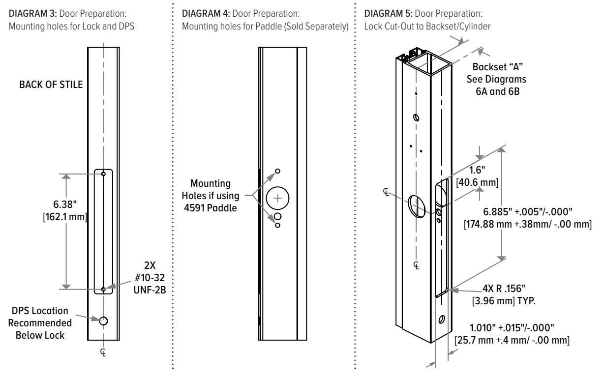
View PDFDL100 Wireless Deadlatch

Installation Instructions
Experience a safer and more open world
Frame and Door DIAGRAM 2B: Door Preparation: Mounting holes for Reader* DOOR Preparation Ø 3/8" [9.5mm]DIAGRAM 2A: Frame Preparation Reader 1 PREPARE the door and frame Harness per Diagrams 2A-5. Ф 2 BACKSET for the mortise cylinder hole is found on Page 2. 7" MAX DIAGRAM 1: Door & Frame Gap FRAME [177.8 mm MAX] For optimal lock performance, the gap between the door and 7.08" CYLINDER frame must meet industry [179.8 mm] SURFACE ₽₩ standard of 1/8". MOUNTED 1.44" Ø 1.25" STRIKE PLATE [36.6 mm] [3.2 mm] [31.8 mm] 1.25" 1.13" [31.8 mm] [28.6 mm] 1.02" [25.9 mm] 2.91" Œ [74 mm] .90" 2X .87" [22.9 mm] [22 mm] *NOTE: Center Reader horizontally on Door Stile. .435' 4X #4 X 1/4" Horizontal placement is Door Stile dependent. [11 mm] UNDERCUT FLAT
HEAD SCREWS
Frame and Door Prep Continued
DIAGRAM 6A: Lock Dimensions
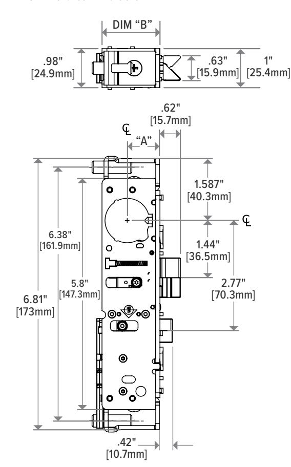
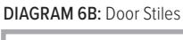
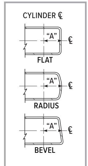
| DIM. A (DOOR) | DIM. B (LOCK) | |
|---|---|---|
| 31/32" | 1-19/32" | |
| [24.6mm] | [40.5mm] | |
| 1-1/8" | 1-49/64" | |
| [28.6mm] | [44.8mm] | |
| 1-1/2" | 2-9/64" | |
| [38.1mm] | [54.4mm] | |
DIAGRAM 6C: Mortise Cylinder Cam. Turning Key / Handle / Paddle DOES NOT
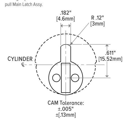
MORTISE CYLINDER CAM
DL100 is operable by any standard 1-5/32" diameter Mortise cylinder with special MS® cam dimensioned as shown.
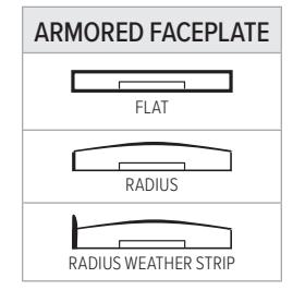
BEVEL ADJUSTMENT
• Flat faceplate can be adjusted for right or left beveled door stile, see Diagram 14 .
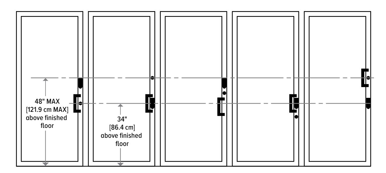
DL100 Location Options for ADA Compliance
DIAGRAM 7:
Reader Mounting
- 1 PERFORM a site survey to ensure the opening is appropriate for the DL100 installation and the RF capability is optimum.
- 2 CONFIRM center of cylinder prep to bottom of reader backplate is not more than 5-1/4", see Diagram 2B.
- 3 REMOVE the backplate from the reader.
- 4 DRILL 3X 1/8" DIA. holes in the backplate as indicated (deburr the holes after drilling) See Diagram 8.
- 5 POSITION reader in desired location on door. See Diagram 2B.
- 6 Using backplate as a template, MARK and DRILL 3X 7/64" DIA. holes and 1X 3/8" DIA. hole in the door. Deburr 3/8" DIA. hole after drilling. See Diagram 2B.
- 7 INSTALL 2X AA lithium batteries into the reader, see Diagram 9.
- 8 INSERT reader cable thru exit hole on backplate, see Diagram 10.
- 9 WRAP grommet on cable, and PRESS grommet into hole on backside of backplate see Diagram 10.
- 10 APPLY RTV/Sealant to 3X holes on backplate prior to fastening 3X screws, see Diagram 11.
- 11 MOUNT backplate to door with the provided 3X #4 X 3/8" selftapping screws, see Diagram 11.
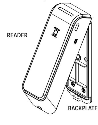
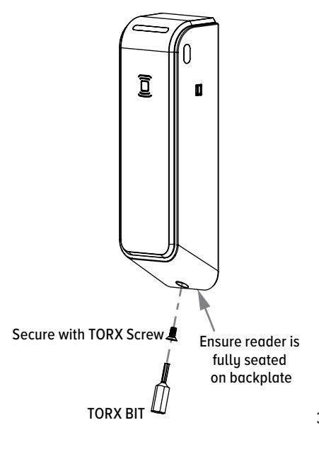
- 12 SECURE reader to backplate with the provided tamper resistant Torx screw, fasten with Torx bit, see Diagram 12. NOTE: Ensure reader is fully seated on backplate.
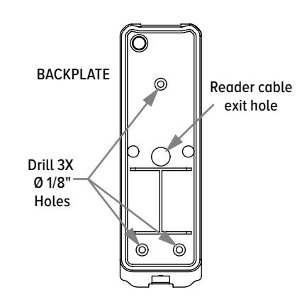
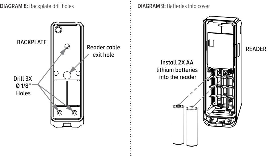
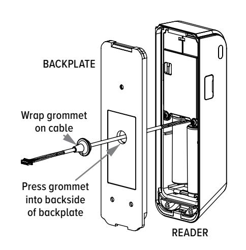
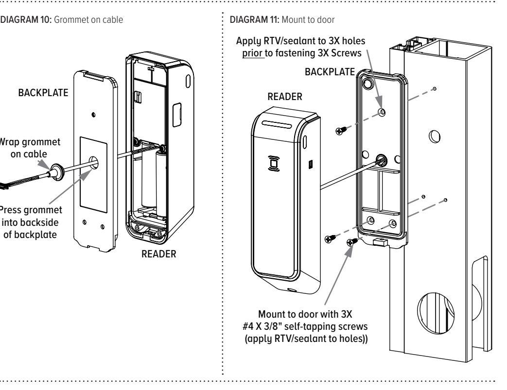
DIAGRAM 12: Secure cover to backplate
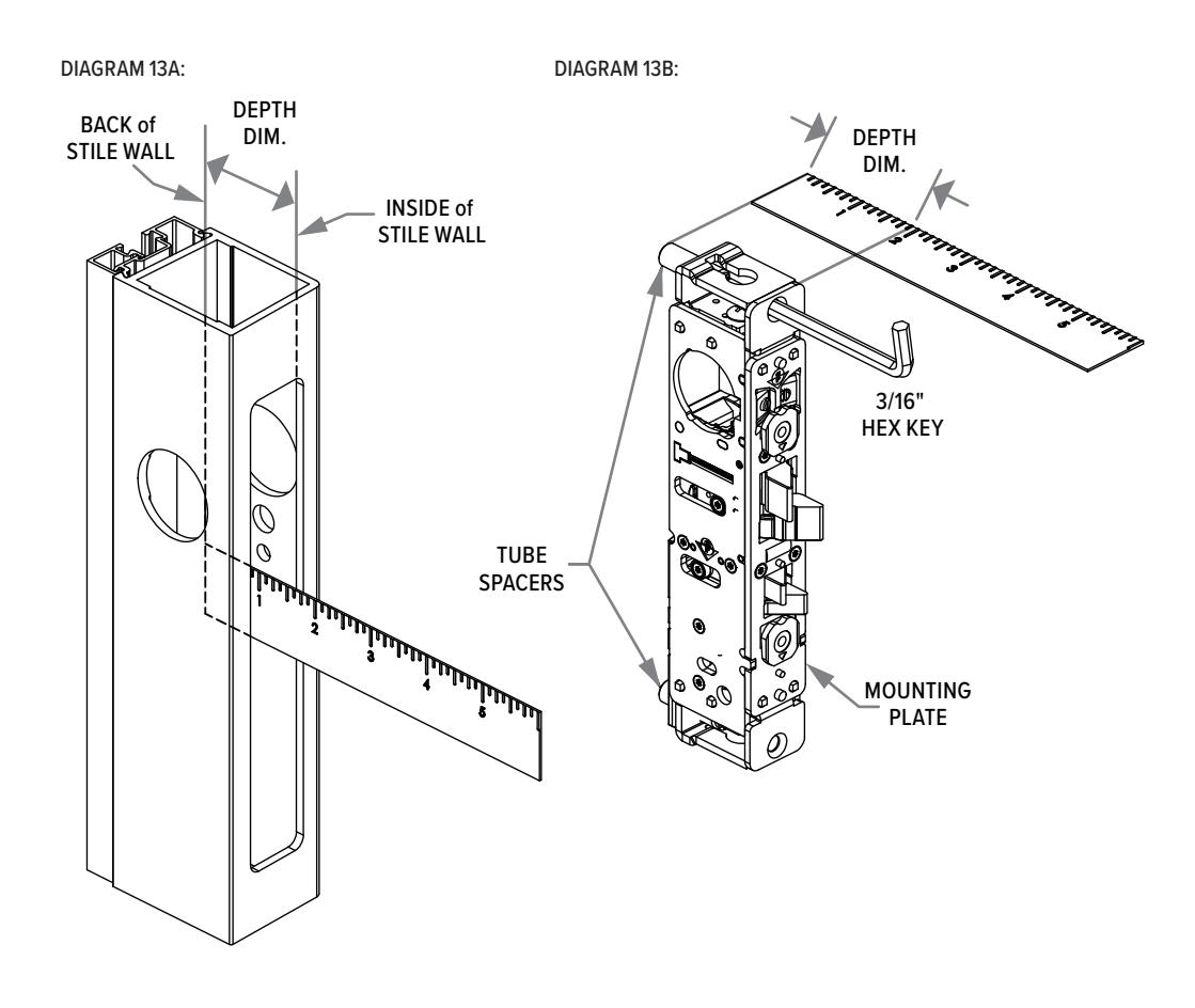
Lock Prep for Traditional Mounting Installations
- 1 MEASURE the depth from the back of the stile to the inside wall, see Diagram 13A.
- 2 MATCH THE DEPTH dimension from face of Mounting Plate to the Tube spacers. Use 3/16" Hex Key for fine adjustment, see Diagram 13B.
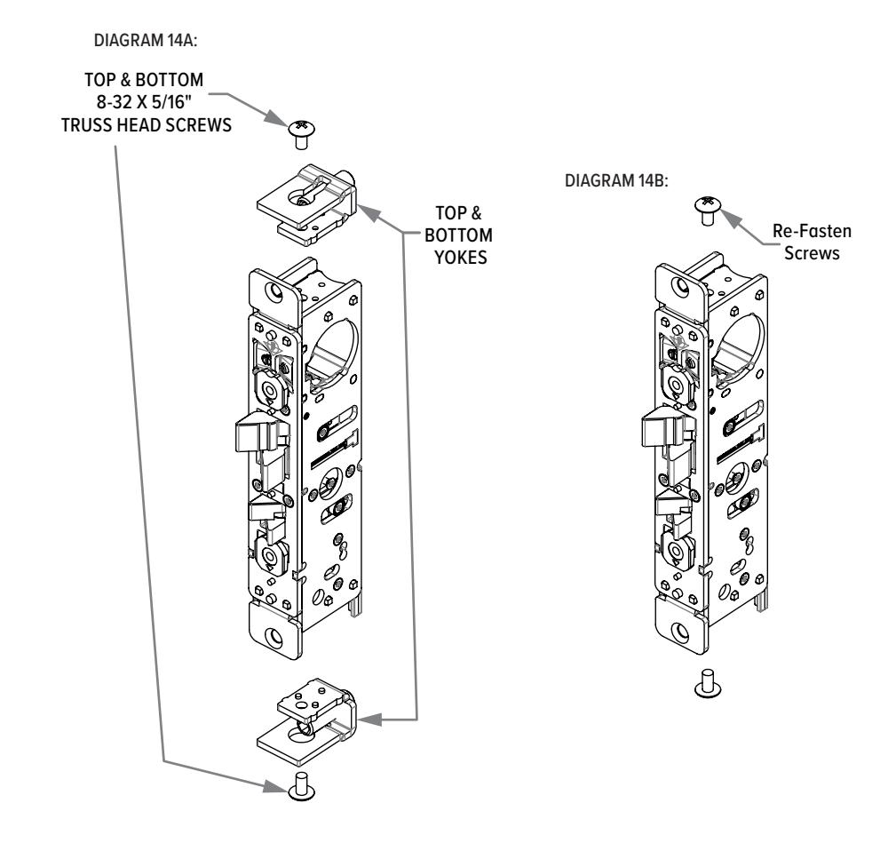
Lock Prep for Mounting Tab Installations Only
- 1 REMOVE top and bottom screws and yokes (adjustable mounting tube brackets), see Diagram 14A.
- 2 RE-FASTEN screws, see Diagram 14B.
Bevel Adjustment
- 1 ROTATE bevel tab to desired hand position, see Diagram 15 .
- 2 Bevel adjustment allows flat faceplate to sit flush with beveled door stile. Radius and Flat Faceplates are included.
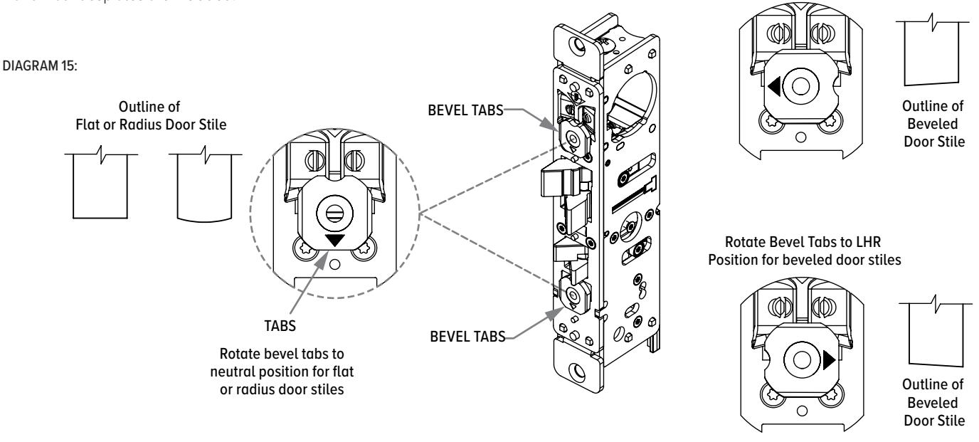
Rotate Bevel Tabs to RHR
Position for beveled door stiles
Wiring Schematic
DIAGRAM 16:
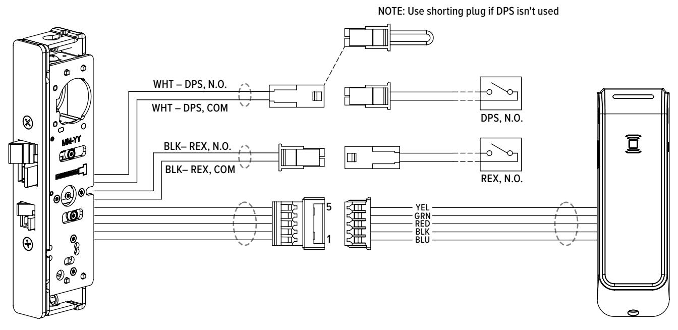
NOTE: These switches have not been evaluated by UL.
Installation Connections
- 1 CONNECT Reader to lock.
- 2 CONNECT DPS (door position sensor) to connector with white wires on lock (use shorting plug if no DPS).
- 3 CONNECT REX (request to exit) to connector with black wires on lock.
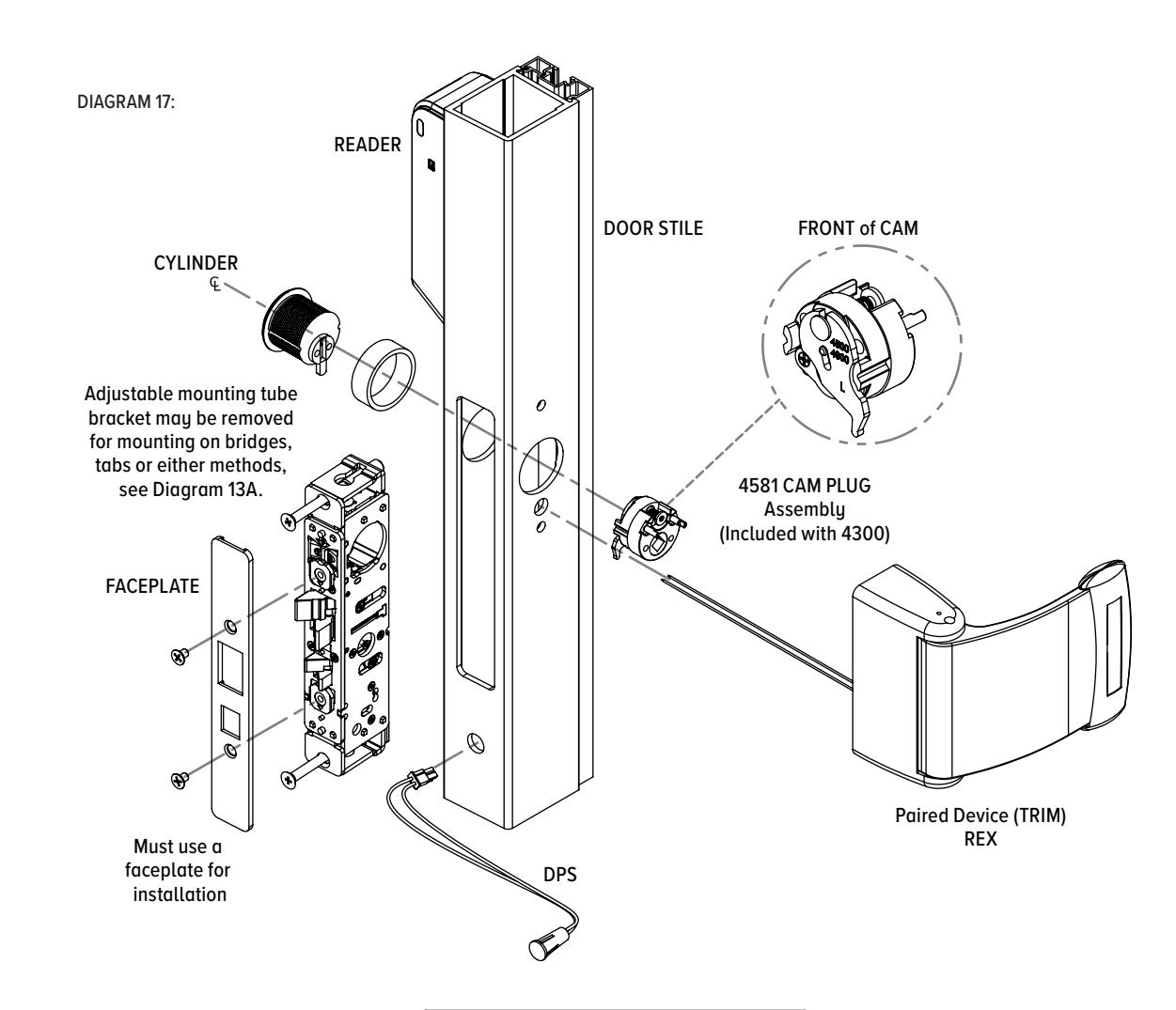
- 4 INSTALL DL100 lock.
- 5 INSTALL cylinder.
- 6 INSTALL cam plug assembly if required by Step 7.
- 7 INSTALL trim, paddle, or cylinder (see separate instructions).
- 8 INSTALL faceplate.
NOTE: See Diagram 16 for Wiring Schematic. NOTE: Verify wire harness is not being contacted by mounting screws.
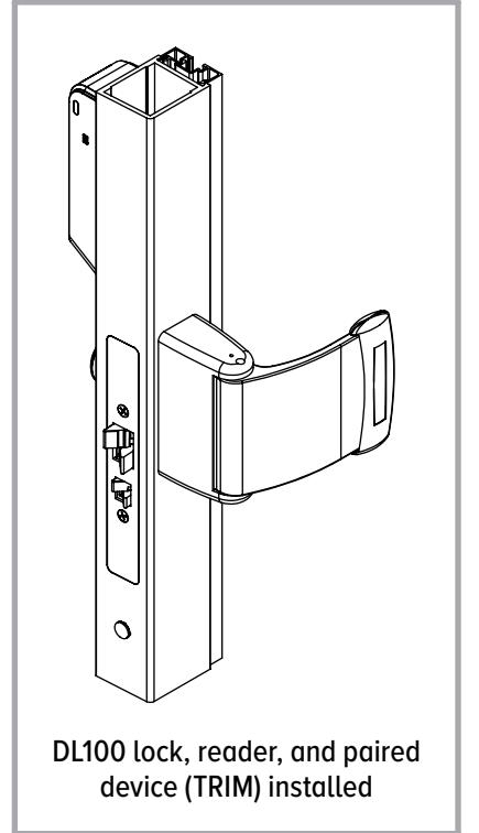
Verify Lock Operation
- 1 INDEPENDENTLY TURN the key or operate the trim to ensure the main latch collapses into the door, releasing the door.
- 2 RELEASE the auxiliary latch and ensure the extended main latch is secure.
Aperio Hub Specifications
Approvals
CE, ETL, FCC, IC, C-Tick
Safety & Emissions
FCC 47CFR Part 15 subpart B and subpart C; IC RSS-210 EN ETSI 301 489-17 v2.1.1; ENETSI 300 328 v1.7.1: EN 60950-1 ed.2 2007
Dimensions
3-1/8" x 3-1/8" x 1-3/16" [82mm x 82mm x 37mm]
Power Supply
8-24 VDC
Current
250 mA minimum
NOTE: This hub has not been evaluated by UL.
Internal Antenna
2 cross polarized dipoles
External Antenna
(Part No. EXT-10-ANT) One reverse polarity SMA external antenna connector. Optional antenna type dipole with max antenna gain of 3.9dBi
Radio Standard
IEEE 802.15.4(2.4GHz) - 15 channels (11-25)
Encryption (RadioCommunications)
AES 128 bits
Wireless Operating Range
Up to 50 ft
Receiver Sensitivity
-100dBm 20% PER
Wireless Transmit Power
10 d Bm/MHz
Class of Protection
IP 20
Operating temperature
41°F to 95°F [5°C to 35°C]
Humidity
< 95% non-condensing
S tatus
LED (red/green/yellow)
LED Codes
| APERIO LED LOCK CODES | ||
|---|---|---|
| (1) ONE Yellow Flash | Card read | |
| (1) ONE Green Flash | Access Granted | |
| (5) FIVE Yellow (1) ONE Red | 111111 | Force Closed (in open mode) |
| Continuous Yellow Flashes (.25 sec every second) | 1 1 1 1 | Comhub busy |
| (1) ONE Red Flash | ı | Access Denied (AC Online) |
| (3) THREE Red Flash | Ш | Access Denied (AC Offline) |
|
Continuous Red Flashes
(.125 sec every second) |
1111 | Lock is Blocked (when closing) |
| (10) TEN Red Flashes | Error in Lock | |
| Continuous Yellow Flashes (.25 sec every 5 seconds) | 1 1 | Low Battery |
|
Continuous Red Flashes
(.25 sec every 5 seconds) |
I I | Dead Battery |
| APERIO LED HUB CODES | |||
|---|---|---|---|
| Steady Green | Online | ||
|
Steady Green
+ (1) ONE Red Flash |
Lock Offline | ||
|
Steady Green
+ (2) TWO Red Flashes |
Access Control Offline | ||
|
Steady Green
+ (3) Three Red Flashes |
- |
Access Control &
Lock Offline |
|
| Flashing Yellow | UHF Communication | ||
Connecting the Hub
The following applies only to Aperio factory paired kits with AH20 Hubs. Connect the Wiegand D1, D0, red, and green LED signals.
Note: The Green LED input is used to grant access to the cabinet lock. If the Green LED signal is not available to indicate approved access, the approval input can be activated by a relay with "NO" attached to Green LED and "C" to GND. The Red LED input is used to indicate access denied. If the RED LED signal is not connected, the lock will flash RED three times when a non-approved card is presented indicating loss of connection to the hub rather than access denied. Any other codes may be reference on the LED reference card.
For questions regarding installation of the hub such as hub placement, coverage area, or materials that may interfere or reduce range, please review the hub installation instructions:
content.assaabloyusa.com/doc/AADSS1177359

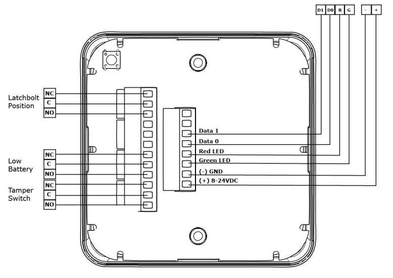
For placement of hub, see AH20/AH30 Installation Instructions
Product Specifications
Approvals
CE, FCC, IC
Wireless Frequency
2.4GHz, IEEE 802.15.4, using AES 128-bit encryption
AA Lithium
Energizer L91 Rated 1.5 VDC, 3 Ah
NOTE: Replace Battery With Energizer L91 batteries only. Use of another battery may present a risk of fire or explosion.

CAUTION: Risk of fire and burns. Do not recharge, disassemble, heat above operating temperature or incinerate. Keep battery out of reach of children and in original package until ready to use. Dispose of used batteries promptly.
Battery Life
2+ years (45,0000 cycles)*
*All battery life claims are approximate and based on a set configuration profile. Battery performance is based on pre-defined system settings such as battery chemistry and battery model used, credential presentation settings (LED/buzzer), UHF polling period, UHF status intervals, and operations per day. Actual battery performance will vary and depends on the factors above.
HID® multiCLASS SE® Technology Credentials Supported
- High Frequency (13.56 MHz)
- HID iCLASS®
- HID iCLASS SE® (SIO-enabled)
- HID iCLASS® Seos™
- HID MIFARE® SE
- HID DESfire® EV1 SE
- MIFARE CLASSIC
- DESfire® EV1
•
Low Frequency (125 kHz)
• HID Prox®, AWID, EM4102, ioProx
NFC/BLE*
Mobile – enabled credentials Reader is compatible with HID Mobile Access version 3.76 and later using mobile devices with BLE version 4.2 and later
Environmental
Operating Temperature (both products)
• 14° to 140° F [-10° to 60° C]
Operating Humidity (both products)
• 0 to 93% relative humidity non-condensing
Certifications
- UL 294 Listed Indoor Rated
- UL 294 Salt Spray Test Compliant
- Tested to IP65 (Reader Only)
- FCC Part 15 & Industry Canada Compliant
- CE RED Radio Equipment Directive 2014/53/EU
UL294 Performance Levels
- Destructive Attack: Level I (No Attack Test)
- Line Security: Level I (No Line Security)
- Endurance: Level IV (100,000 Cycles)
- Standby Power: Level I (No Secondary Power)
Safety and Emissions
- FCC 47CFR Part 15, subpart C
- IC RSS-102
- RSS-210
- RSS-247
- RE Directive 2014/53/EU, EN 301 489-1, EN 301 489-3, EN 300 440, EN 300 330, EN 300 328, EN 62368-1, EN 62479
WARNING
FCC Statement
This equipment has been tested and found to comply with the limits for a class B digital device, pursuant to part 15 of the FCC Rules. These limits are designed to provide reasonable protection against harmful interference in a residential installation. This equipment generates, uses, and can radiate radio frequency energy and if not installed and used in accordance with the instructions, may cause harmful interference to radio communications. However, there is no guarantee that interference will not occur in a particular installation. If this equipment does cause harmful interference to radio or television reception, which can be determined by turning the equipment off and on, the user is encouraged to try to correct the interference by one or more of the following measures:
- 1. Reorient or relocate the receiving antenna.
- 2. Increase the separation between the equipment and receiver.
- 3. Connect the equipment into an outlet on a circuit different from that to which the receiver is connected.
- 4. Consult the dealer or an experienced radio/TV technician for help.
Operation with non-approved equipment is likely to result in interference to radio and TV reception. The user is cautioned that changes and modifications made to the equipment without the approval of manufacturer could void the user's authority to operate this equipment. To comply with FCC and Industry Canada RF radiation exposure limits for general population, the module must be installed to provide a separation distance of at least 20cm from all persons and must not be colocated or operating in conjunction with any other antenna or transmitter.
This module is labeled with its own FCC ID and IC Certification Number. If the FCC ID and IC Certification Number are not visible when the module is installed inside another device, then the outside of the device into which the module is installed must also display a label referring to the enclosed module. In that case, the final end product must be labeled in a visible area with the following:
Contains FCC ID: VC3-R100V3 Contains IC: 7160A-R100V3
IC Statement
This device complies with Industry Canada license-exempt RSS standards(s). Operation is subject to the following two conditions:
- (1) this device may not cause interference, and
- (2) this device must accept any interference, including interference that may cause undesired operation.
Conformité aux normes IC
Cet appareil est confrome avec Industrie Canada exempt de license RSS standard(s). Son fonctionnement est souimes aux deux conditions suivantes:
- (1) cet appareil ne peut causer d'interférences, et
- (2) cet appareil doit accepter toute interference, y compris des interférences qui peuvent provoquer un fonctionnement indésirable du périphérique.
CE Declaration of Conformity
content.assaabloyusa.com/doc/AADSS1179512&.pdf


adamsrite.com | 800 626 7590 techsupport.adamsrite@assaabloy.com 10027 S. 51st Street, Ste. 102 Phoenix, AZ 85044 USA
Printed in the U.S.A.
Patent pending and/or patent www.assaabloydss.com/patents Copyright © 2022, Hanchett Entry Systems, Inc., an ASSA ABLOY Group company. All rights reserved. Reproduction in whole or in part without the express written permission of Hanchett Entry Systems, Inc. is prohibited. 80-0180-497_1