Adams Rite 3100, 8100, 8200 Exit Device Operating Manual
Open the original PDF document
View PDF

ASSA ABLOY
Adams Rite Manufacturing Co.
260 Santa Fe Street Pomona, CA 91767
Phone: 800-872-3267 Fax: 800-232-7329
www.adamsrite.com
OWNER'S MANUAL
3100/8100/8200 SVR EXIT DEVICE
Adams Rite Manufacturing Co. 260 Santa Fe Street, Pomona, CA 91767 Phone: 800-872-3267 • Fax: 800-232-7329 www.adamsrite.com
CONTENTS
| Owner's Record | . 2 |
|---|---|
| Exit Device Operation | . 3 |
| Maintenance | . 6 |
| How to Obtain Replacement Parts & Service | . 6 |
| Troubleshooting | . 7 |
| Replacement Parts Listing | . 8 |
| Limited Warranty |
WHAT THIS OWNER'S MANUAL CAN DO FOR YOU
- It shows exactly how to operate your exit device.
- It shows you simple things to do and check before you call for service, so you may save the cost of an unnecessary service call.
- It provides a complete listing of service replaceable parts.
- It contains your Adams Rite Limited Warranty and what steps to take for service.
OWNER'S RECORD
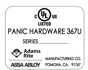
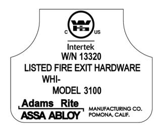
The model number is located on the hinge stile mounting base as shown below. Refer to this number and the additional information below when you call upon your local Adams Rite dealer regarding this product.
| Model No. | 3100/8100/8200 |
|---|---|
| Finish | |
| Door Size | |
| Hardware Supplier | |
| Date Installed |
LIMITED WARRANTY
Adams Rite Manufacturing Co. (hereinafter ADAMS RITE) manufactures its products in a manner to be free of defects. Should any defect of manufacture (in material or workmanship) occur in its products, ADAMS RITE, upon prompt notification and proof to its satisfaction that the product was defective in manufacture for the use intended by ADAMS RITE, will at its option, exchange the product, repair the defect or refund the price charged by ADAMS RITE, FOB factory based on the following schedule:
- All mechanical products for five (5) years from the date of manufacture;
- All electrical products (including EL and ED exit devices) for three (3) years from the date of manufacture;
- The RITE Door® for five (5) years from the date of manufacture;
- UltraLine Electric Strikes for five (5) years from the date of manufacture.
<u>Limitations and exclusions</u>: This is a limited warranty and is in lieu of all other warranties including the implied warranties of merchantability and fitness for use) and under no circumstances shall ADAMS RITE be liable for any incidental or consequential damages or losses.
This warranty covers products as outlined above manufactured from May 1, 2003 forward.
This warranty does not cover damages from such causes as abuse, accident, neglect, fire or freight damage.
WARRANTY CONDITIONS
The selling dealer from who this exit device was purchased is responsible for advising the purchaser of the period of no charge warranty exchange, repair or refund. Replacement parts under the terms of the warranty must be furnished by the Adams Rite dealer or agency.
FACTORY ASSISTANCE
If the purchaser is unable to locate a service agency, or if the purchaser does not receive satisfaction from the source of which the exit device was purchased, or from local dealer, write or contact ADAMS RITE at the following address:
Adams Rite Manufacturing Co. 260 Santa Fe Street Pomona, CA 91767 Phone: 800-872-3267
Fax: 800-232-7329
EXIT DEVICE OPERATION
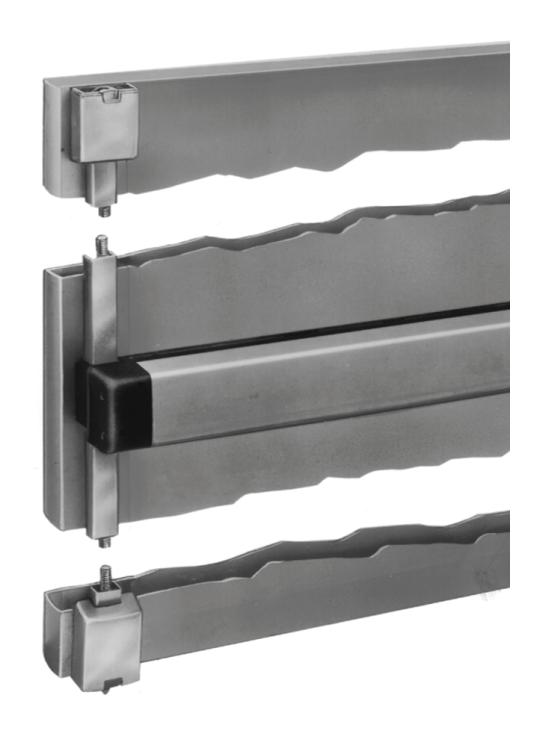
The Adams Rite Surface Vertical Rod (SVR) devices for metal, wood and glass doors provide for life safety and security by use of a rotating top bolt and post type header strike. The bottom bolt is a hardened steel, with a conical tip to center in the simple drilled strike required in the threshold.
When the push bar is depressed, the top and bottom rods retract to release the door. Upon closing, the actuator deadlatches around the top strike post. Action of the top bolt deadlocks the bottom bolt as well. Exterior entrance can be gained by key or with the extensive line of entry trim available from Adams Rite.
PUSH BAR DOGGING
[Not applicable to 3000 Series (Fire Rated Devices)]
CAUTION: Over-rotation of the key past the prescribed 1/4 turn can cause damage to the Exit Device.
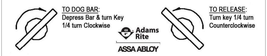
Dogging the push bar disables the latching function, making the door a simple push/pull operation. To dog the device, depress the push bar completely and turn the hex key 1/4 turn clockwise. To release, turn the hex key 1/4 turn counterclockwise.
END CAP REMOVAL/REPLACEMENT
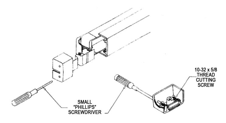
To facilitate maintenance procedures, the two end caps can be removed. Access to the concealed attachment screws is achieved by inserting a small Phillips tip screwdriver through the holes located in the end cap.
When replacing end caps, be certain the screws are snapped in screw clips on inside of end caps. Hand tighten ONLY!
TOP STRIKE POSITIONING
The top post strike must be properly located, and tightened securely, for the device to operate. Position the strike assembly so that it is centered on the hole cutout. Tighten with 5/32 Allen wrench. Ensure proper engagement with top actuator of exit device. Make adjustments if necessary.
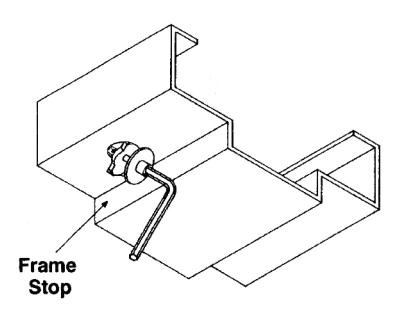
CAUTION: A proper frame stop must be used in conjunc-
tion with the door/exit device.
8100 SVR
Owner's Manual
SVR Exit Device
Mounting Bar Final Assembly Not Available
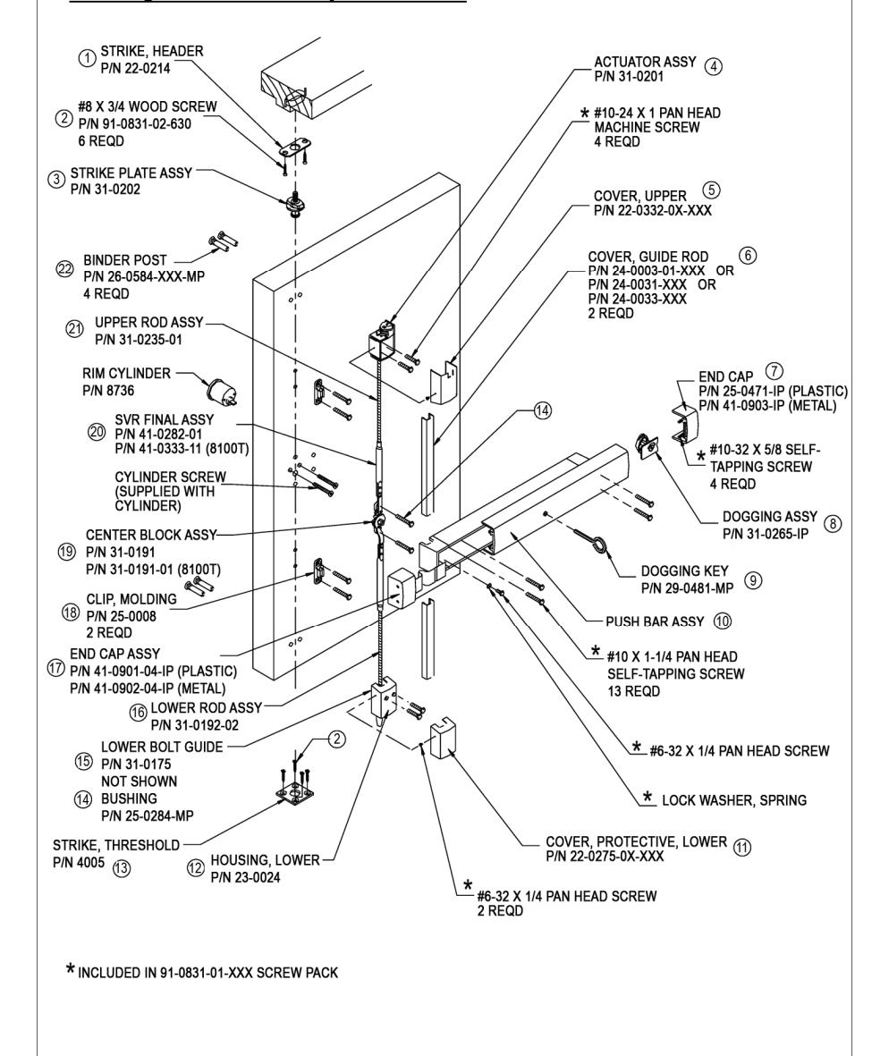
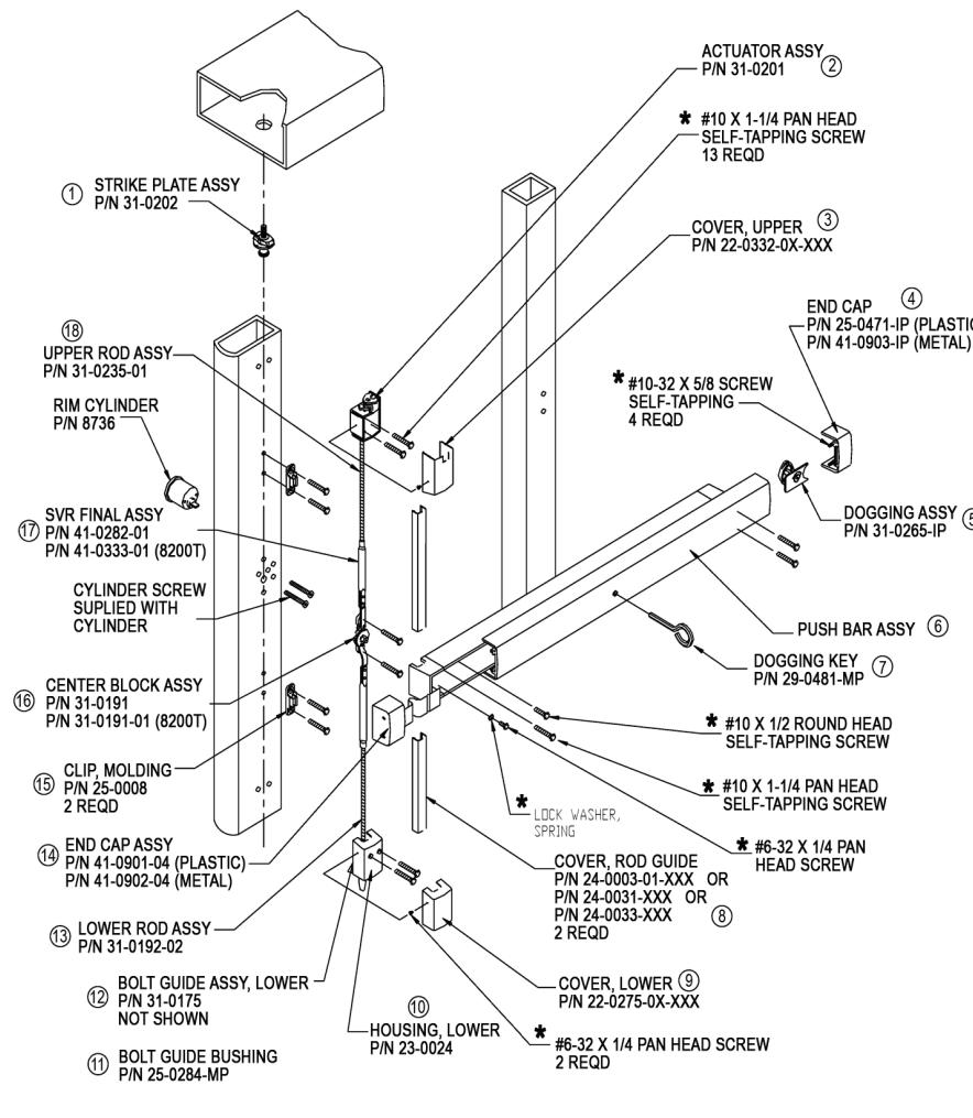
REPLACEMENT PARTS AVAILABLE FROM ADAMS RITE
3100 SVR
Mounting Bar Final Assembly Not Available ACTUATOR ASSY (2) P/N 31-0331 ##10-24 X 1 PAN HEAD 1) STRIKE PLATE MACHINE SCREW ASSY 4 REOD P/N 31-0202 COVER, UPPER P/N 22-0332-0X-XXX BINDER POST P/N 26-0584-XXX COVER, ROD GUIDE P/N 24-0003-01-XXX OR 4 REQ'D P/N 24-0031-XXX OR P/N 24-0033-XXX UPPER ROD ASSY 2 DEOD P/N 31-0333-01 (16) SVR FINAL ASSY # #10 X 1-1/4 PAN HEAD P/N 41-0235-01 OR SELF-TAPPING SCREW P/N 41-0333-01 (3100T) 13 REQD END CAP (5) CYLINDER -P/N 41-0903-IP P/N 8736 (MFTAL) CYLINDER SCREW (SUPPLIED WITH #10-32 X 5/8 SELF CYLINDER) TAPPING SCREW CENTER BLOCK ASSY 4 REQD (15) P/N 31-0191 P/N 31-0191-01 (FOR 3100T) (14) CLIP, MOLDING PUSH BAR ASSY (6) P/N 25-0008 #10 X 1-1/4 PAN HEAD SELF-TAPPING SCREW #6-32 X 1/4 SCREW, PAN HEAD 2 REQD LOCK WASHER, SPRING (13) END CAP ASSY P/N 41-0902-04-IP (METAL) 12 LOWER ROD ASSY-#10-24 X 1 PAN HEAD MACHINE SCREW BOLT GUIDE ASSY. LOWER- ① P/N 31-0175 NOT SHOWN COVER, LOWER (10) BUSHING, BOLT GUIDE P/N 22-0333-0X-XXX P/N 25-0284-MP #6-32 X 1/4 PAN HEAD SCREW (9) HOUSING, LOWER STRIKE (8) P/N S222-06R04-XXX P/N 23-0059 P/N 22-0125 2 REOD * INCLUDED IN 91-0831-01-XXX SCREWPACK NOTE: ALSO COVERS PARTS USED IN 3100T
TOP ACTUATOR OPERATION
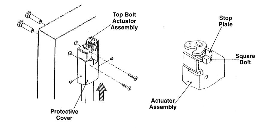
Proper operation of this device relies heavily on the correct adjustment of the top actuator. The amount of travel of the bottom bolt is also governed by this adjustment. The diagram below shows the correct relationship of the square bolt to the top actuator.
- 1. With actuator assembly in locked position and push bar released, end of square bolt should engage stop plate as shown below.
- 2. For fine adjustment, take off actuator assembly by removing the protective cover and the two screw fasteners.
- 3. Adjust bolt up (counterclockwise) or down (clockwise) to conform to the illustration below. In the locked position, the top of bolt stop plate surface should be flush.
- 4. Reinstall actuator assembly. Tighten the screws securely.
MAINTENANCE
Exit devices are designed for life safety first. Adams Rite devices are cycle tested in excess of one million operations, both as prototypes during design and as quality control samples periodically during production. Atmospheric and other localized conditions vary greatly, but extremely dirty, salty or abrasive situations could require service attention such as lubrication of moving parts from time to time to assure reliability. Service personnel should be reminded that life safety is the goal.
Other maintenance that might be required specifically for an SVR device is:
- Tightening of top strike screws;
- Ensuring debris is clear from the bottom strike cutout;
- Tightening of push bar mounting screws.
HOW TO OBTAIN REPLACEMENT PARTS & SERVICE
The merchandise that you have purchased from us has been carefully engineered and manufactured under Adams Rite's rigid quality standards and should give you many years of satisfactory and dependable operation. However, like all mechanical merchandise, it may require replacement parts or maintenance.
The Parts Manual is also available on Adams Rite's web page at the following address:
http://www.adamsrite.com/NewFiles/partsman_home.htm
TROUBLESHOOTING GUIDE
| Symptom | Possible causes | Corrective action |
|---|---|---|
| Device will not dog. | A. Push Bar not fully depressed. B. Dogging assembly damage. | C. Review dogging procedures on page 3. D. Remove and inspect. Replace if necessary. |
| Device not latching. | A. Device is dogged. B. Closer not set at sufficient speed. C. Improper alignment of top strike post. D. No, or improper, cutout for bottom bolt. | A. Undog device per instructions on page 3. B. Make appropriate adjustments. C. Strike must fully engage top actuator. It must be far enough toward door to fully rotate top bolt. Refer to page 4. D. Hole should be 1/2" in diameter located directly below bottom bolt with the door in the fully closed position. The hole should be free of any debris. |
| Bottom bolt dragging or is hitting threshold. | A. Top actuator out of adjustment. B. Bottom bolt out of adjustment. | A. Refer to page 5 for instructions on top actuator adjustment. B. Remove bottom bolt guide. Rotate bolt for desired height. |
| Excessive rod noise. | A. Bottom bolt guide bushing missing. B. Molding clip guides missing from top or bottom rods. | A. Remove bottom bolt guide to ensure bushing is in place and not damaged. Bushing should be in the down position. B. Molding clips can be ordered from local supplier. Taller doors will require an adder. |
| Rod covers easily knocked off. | A. Molding clip guides missing or damaged. B. Rod cover not cut to proper length. The cover should be captured inside push bar mounting base and bottom bolt cover housing. | A. Inspect molding clip for damage. Replace if necessary. Taller doors will require additional clip guides. B. Replace rod cover, cut to correct length. |