ASSA ABLOY ACCENTRA SL8700 Series Installation Instructions_80-9086-0017-010
Open the original PDF document
View PDFInstallation Instructions
80-9086-0017-010 (8-95)
Yale Mortise Locks SL8700 Series
NOTE TO INSTALLER
FAILURE TO FOLLOW THESE INSTRUCTIONS COULD RESULT IN DAMAGE TO THE LOCK AND VOID THE FACTORY WARRANTY.
What does the door look like?
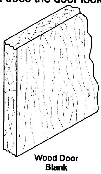
Refer to Section I-A-1
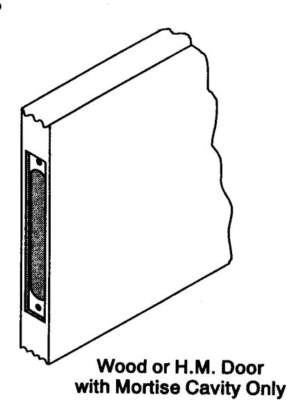
Refer to Section I-B-1
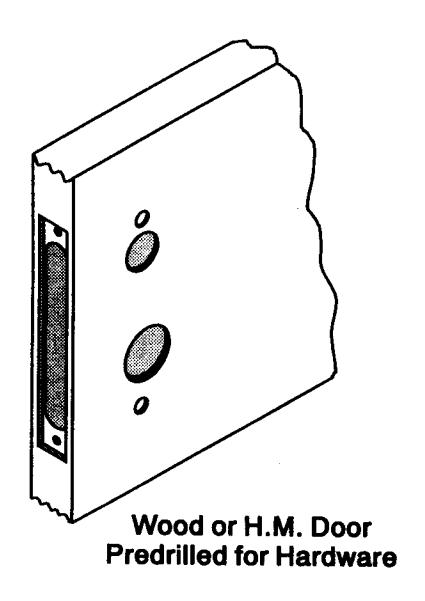
Refer to Section II
What is the hand of the door?
Face the door from the outside to determine it's hand. The outside is the key side of an entrance door or the corridor side of a room door. The outside of a single communicating door is the side opposite the hinges. The outside of twin communicating doors is the space between the doors.
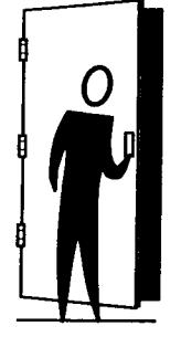
Left Hand Reverse: Hinges on left, opens outward. For handed locks, specify LHR.
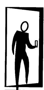
Left Hand: Hinges on left, opens inward. For handed locks, specify LH.
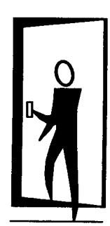
Right Hand: Hinges on right, opens inward. For handed locks, specify RH.
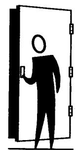
Right Hand Reverse: Hinges on right, opens outward. For handed locks, specify RHR.
If the lock body is not correct hand, refer to Section II "How to change Hands".
Installation Suggestions
The Lock Body must be supported properly. IN WOOD DOORS: If the Mortise Cavity is too wide, shims may have to be added to insure lock is centered in door. If Lock Body can move from side to side it can cause cover screws to loosen and bind lock. IN HOLLOW METAL DOORS: Be sure that the support fingers, at back of Lock cavity, keep Lock Body centered in Door. See Section III Figure 6.
If the Lock Body Cover is removed for any reason, such as to change hand of the lock it is recommended that screw locking compound (such as Loctite ) be applied to the cover screws to insure that they don't loosen. When applying the locking compound, avoid contact with moving parts of the lock.
SECTION I - Prepare the Door
I-A. Blank Wood Door and Frame Preparation
1. Mark door and position template.
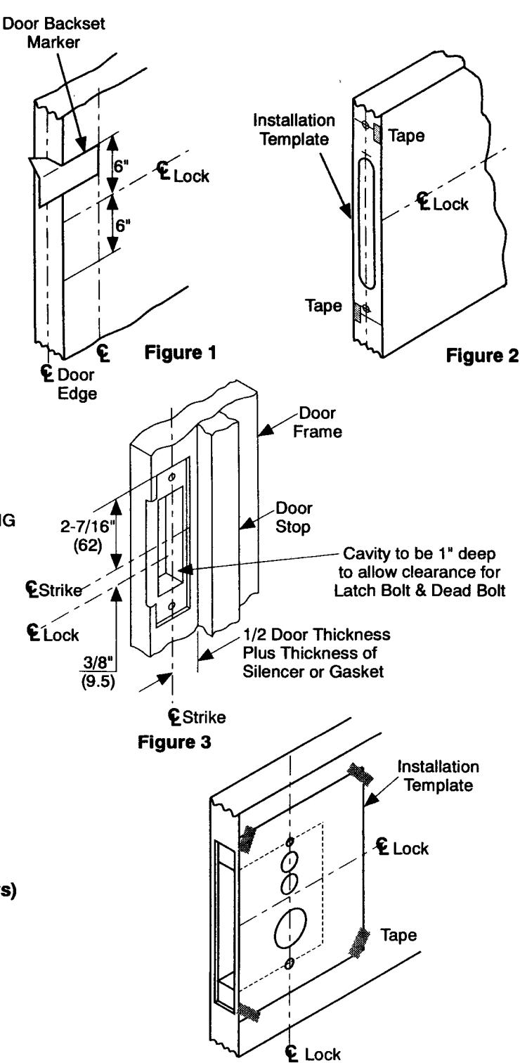
- a. Draw a horizontal centerline for the lock on the edge and on both sides of the door at the desired height above the finished floor line. Standard height for horizontal center line is 39-15/16" above finished floor. (See Figure 1.) NOTE: If mortise for strike already exists in frame, locate the horizontal centerline of the lock using strike mortise as reference. Standard horizontal centerline of strike is 3/8" above lock centerline or 40-5/16" above finished floor.
- Using the door backset marker, draw a vertical centerline on both sides of the door. (See Figure 1.)
- c. Draw a vertical line on center of door edge.
- d. Take installation template and cut apart as shown on template.
- e. Align the middle section of template with the horizontal and vertical centerlines on door edge. Use tape to hold in place. (See Figure 2.)
- f. Mark centers of holes for mortise on edge of door. Mark top of armor front and holes for attaching screws.
- g. Mark horizontal position of strike on jamb using the refer ence centerline on installation template. Mark location of strike lip. FIRST DETERMINE IF SILENCERS OR GASKETING ARE TO BE USED. To locate vertical centerline of strike take half the door thickness PLUS the thickness of silencer or gasket (if used) and use this dimension to locate the strike centerline from the doorstop (see Figure 3).
2. Mortise and drill door and frame.
- Mortise door edge for lock body. Drill pilot holes for attaching screws.
- Attach armor front to lock body, set front of lock to suit door edge (beveled or flat) by loosening screws at the top and bottom of case. Retighten screws securely.
- Slide lock body into cavity. Align armor front with top mark. Use lock front as template and mark outline.
- d. Mortise door edge for lock front (7/32" deep).
- e. Mortise jamb for strike (3/32" deep). Be sure to mortise 1" (25mm) deep to accommodate lock bolts or strike box if used. (See Figure 3.)
I-B. Locate and Drill Function Holes (Wood and H.M. Doors)
1. Mark door and position template.
- a. Draw a horizontal centerline for the lock on both sides of the door at the desired height above the finished floor line. Standard height for horizontal centerline is 39-15/16" above finished floor (see Figure 1). (You may already have done this in Step I A.)
- Using the door backset marker, draw a vertical centerline on both sides of the door. (See Figure 1.)
- c. Compare number of lock being installed with the chart on the installation template (see Figure 5).
- d. Position installation template on outside of door so that horizontal line on door and vertical points line up with vertical centerline on door. Mark holes to be drilled, (To avoid shifting of template, it may be taped to the door during this step.) See Figure 4.
- e. Repeat Step 1d for inside of door.
2. Drill door.
a. Bore lock trim holes at lock trim marks (Steps 1d and 1e). To avoid splintering wood, bore thru holes from both sides of door. (Note hole sizes on installation template and Figure 5).
| Hole Chart (See installation template) | |||||||
|---|---|---|---|---|---|---|---|
| Hole | Sizo | Used For | |||||
| 1.0.0 | H.M. Door | Wood Door | - Used i oi | ||||
| Α | 1-7/8 (48) Dia | 1-7/8 (48) Dia. | Lever | ||||
| В | 1-1/4 (32) Dia | 1-1/4 (32) Dia. | Cylinder | ||||
| С | 3/4 (19) Dia. | 3/4 (19) Dia. |
Thumbturn or
Emergency Key |
||||
| D | 3/4 (19) Dia. | 3/4 (19) Dia. | Hotel Indicator | ||||
| G | 1/2 (13) Dia. | 1/2 (13) Dia. | Escutcheon Plate Thru Bolts | ||||
Figure 4
Figure 5
SECTION II - How to Change Hands (If necessary)
Disassembly
Reassembly
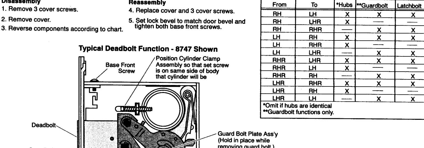
To Change Lockset Hand
Reverse Following As Required
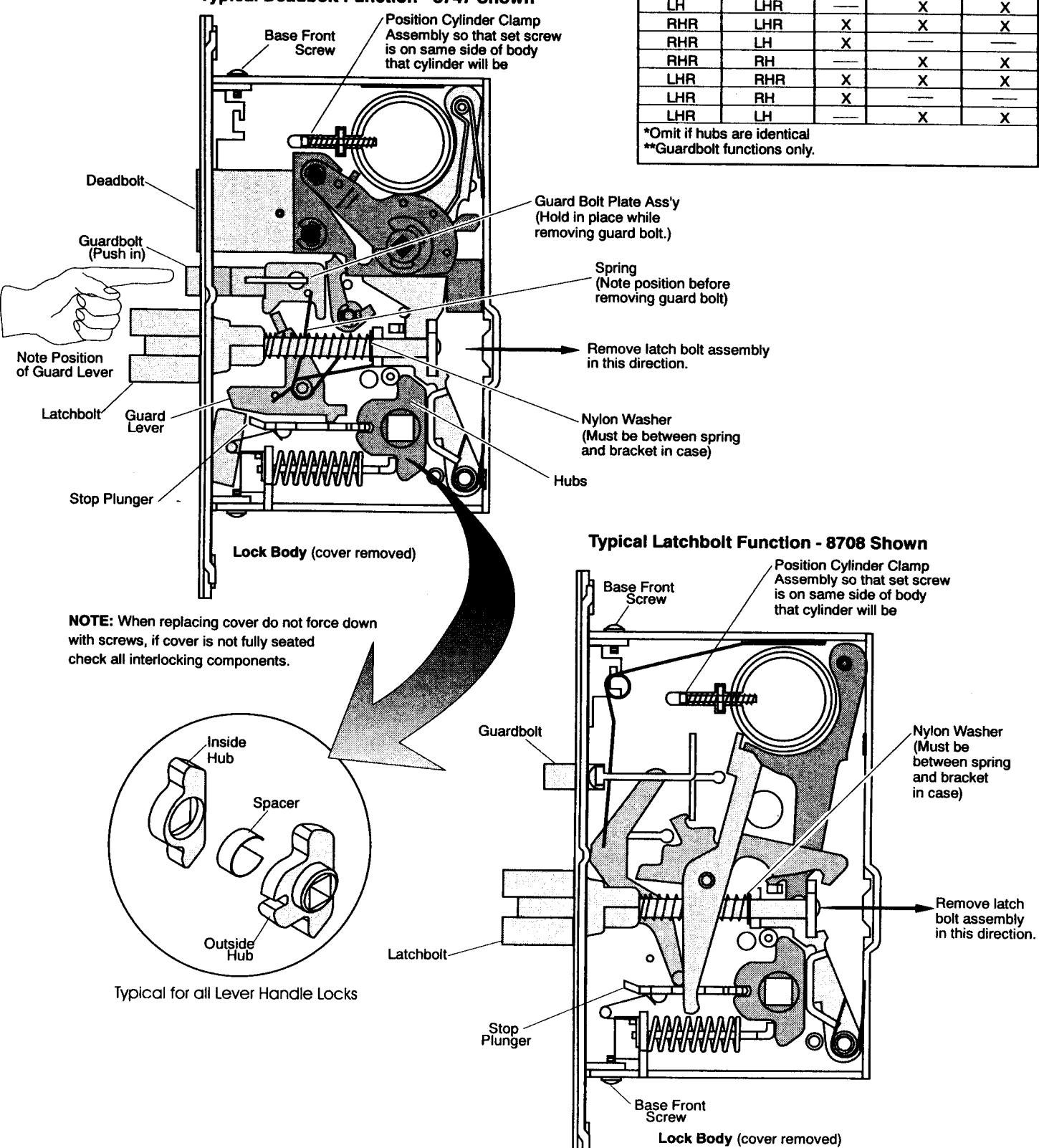
SECTION III - Installation
A. Install Lock Body and Strike.
-
1. Install lock in Wood or H.M. door.
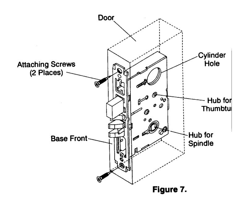
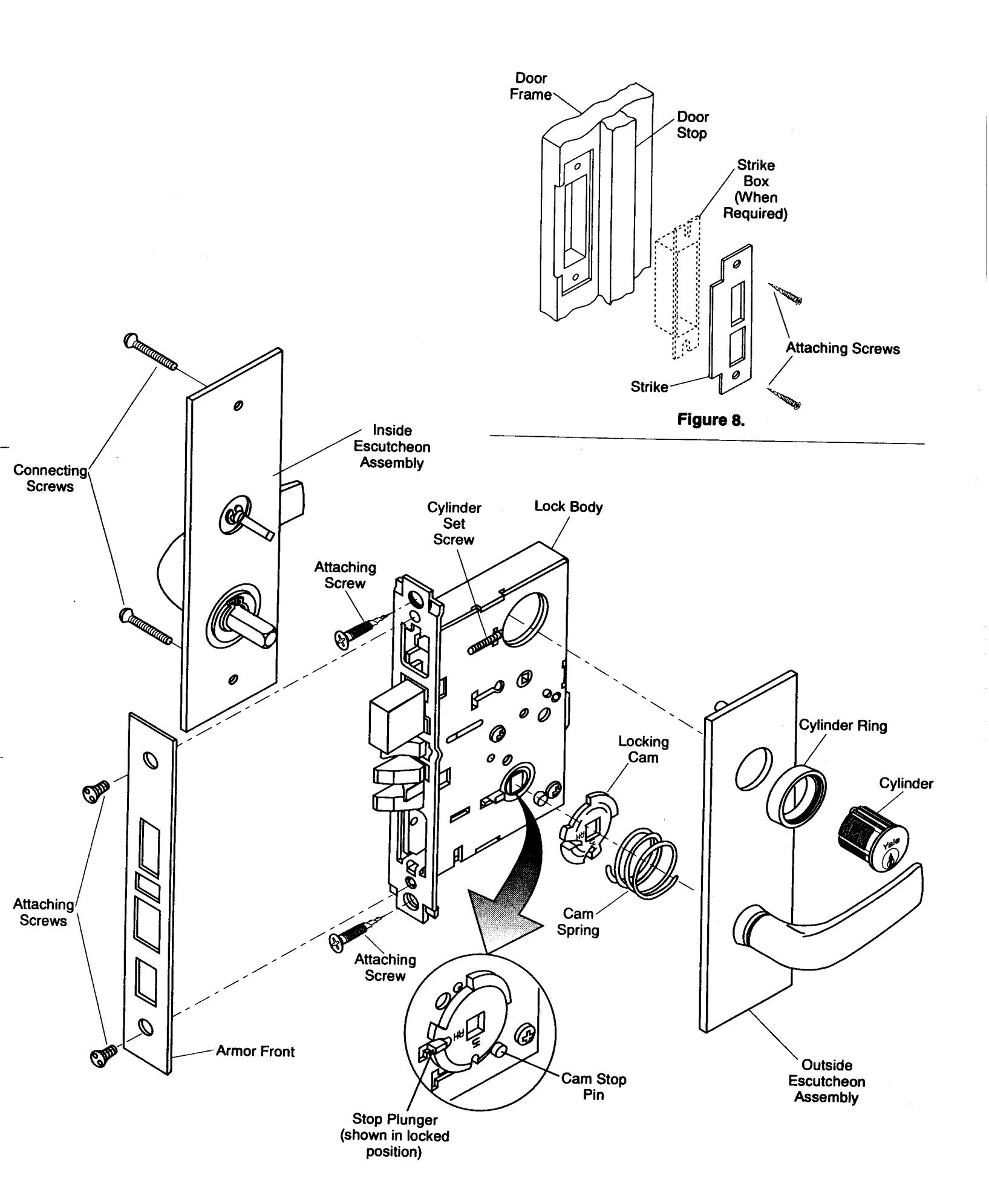
- a. Insert lock body into cavity in door and secure base front with two (2) #12 combination attaching screws. Make sure lock is positioned in cutout properly. (See Figures 6 and 7.)
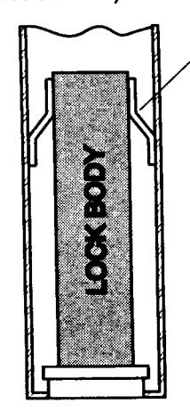
Make sure support fingers hold lock body in center of door. (Adjust as required.) If fingers are not in door, extra material will have to be added to door to keep lock body centered in door.
Figure 6. Hollow Metal door reinforcing.
-
2. Install strike.
- a. Attach strike to jamb using two (2) #12 combination attaching screws (see Figure 8).
B. Install Trim.
-
Take outside trim (escutcheon plate with mounting posts attached) and position lever as it will be on the door.
Place cam spring over spindle and slide locking cam onto spindle.
- NOTE: Cam has to be positioned for proper hand. See Figures 9 and 10.
- Position escutcheon on outside of door with mounting posts going through holes in door and lever spindle going into hub in lock body.
- Place inside escutcheon on door with lever positioned properly. Insert spindle into hub in lock body. (If lock function has a deadbolt, position thumbturn upright and insert shaft of thumbturn into deadbolt hub. (See #14 in section IV)
- Connect the two escutcheons together with two (2) spanner head connecting screws.
- 5. Install cylinder if required. Slip cylinder ring over threaded body of cylinder. Thread cylinder into lock body. Make sure the word "Yale" on cylinder face is Right side up. Tighten cylinder set screw which is accessible through the front of the lock.
- 6. Attach armor front. (If lock has a deadbolt, extend bolt before installing front.)
- Check operation of lock. If binding of levers is noticed, loosen escutcheon screws and adjust position to allow free movement of handles. Retighten screws.
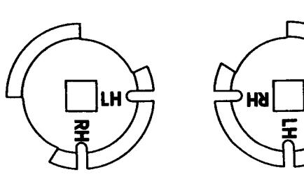
LH and LHR Door
RH and RHR Door
Figure 9. Locking Cam
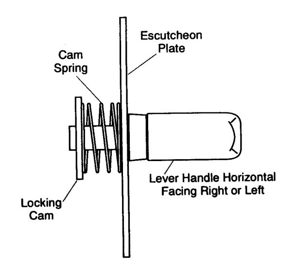
Figure 10. Locking Cam Installation

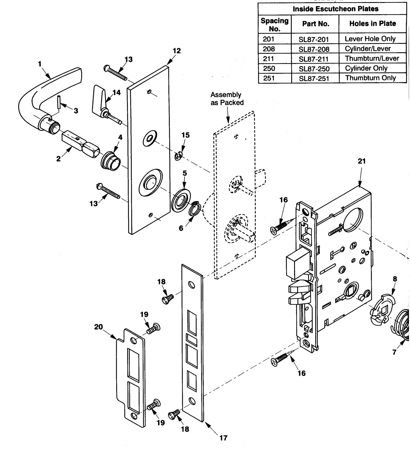
PARTS LIST
| Manual British | |||||
|---|---|---|---|---|---|
| Item | Part No. | Qty. | Description | Finished Component | |
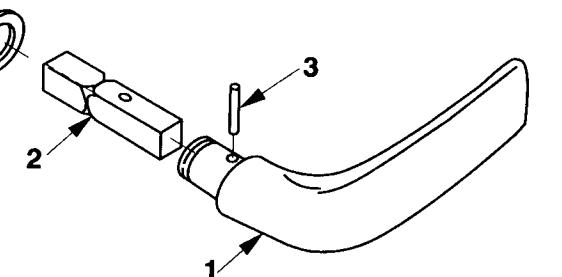
| 1 | 10-0904-2200-018 | 2 | JN Lever Handle | / | |
| 10-0904-2162-018 | AU Lever Handle | / | |||
| 2 | 50-1178-1070-048 | 2 | Spindle | ||
| 3 | 99-9999-3979-023 | 2 | Roll Pin | ||
| 4 | 50-8700-2067-018 | 2 | Thimble Insert | ||
| 5 | 50-8700-1055-048 | 2 | Washer | ||
| 6 | 99-9999-4635-023 | 2 | Retaining Ring . | ||
| 7 | 50-8731-1011-999 | 1 | Cam Spring | : | |
| 8 | 50-8700-1056-048 | 1 | Locking Cam | ||
| 9 | 2153 x 1-1/8" | 1 | Cylinder | ||
| 10 | 10-1765-2001-025 | 1 | Cylinder Ring | ||
| 11 | See Chart I | 1 | Outside Escutcheon Plate | \ \ \ \ \ \ \ \ \ \ \ \ \ \ \ \ \ \ \ | |
| 12 | See Chart II | 1 | Inside Escutcheon Plate | - | |
| 13 | 81-0073-5524-999 | 2 |
Connecting Screws
#10-24 x 1-1/4" Spanner Oval Head (Screw Pack #81-9500-0047-033) |
✓ | |
| 14 | 50-1824-0008-033 | 1 | Thumbturn and Shaft Assembly | _ | |
| 15 | 99-9999-4511-999 | 1 | Retaining Ring |
|
|
| 16 | 81-2012-0620-018 | 2 | Attaching Screws #12-12-24 x 1" Flathead Combination Wood/Machine Screw | ||
| 17 | Varies by Function | 2 | Armor Front | 1 | |
| 18 | 81-0072-5404-999 | 1 |
Armor Front Screws
#8-32 x 1/4" Flat Spanner Head |
· | |
| 19 | 81-0032-5612-018 | 2 | Strike Screws #12-24 x 1/2" Flat Spanner Head | / | |
| 20 | 2810 | Strike Plate (Latch Bolt) | • | ||
| 20 | 2811 | 1 | | Strike Plate (Latch Bolt x Deadbolt) | ||
| 21 | SL8700 | 1 | Lock Body (Specify Function) | * | |
Assembly as Packed
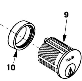
CHART I
| | ( | Outside Escutcheon Plates | |||||||
|---|---|---|---|---|---|---|---|---|
|
Spacing
No. |
Part No. | Holes in Plate | ||||||
| 201 | SL88-201 | Lever Hole Only | ||||||
| 208 | SL88-208 | Cylinder/Lever | ||||||
| 210 | SL88-210 | Cylinder/ Indicator/Lever (Hotel Function) | ||||||
| ١ | 211 | SL88-211 |
Emergency Key/Lever
Only (8702 Function) |
|||||
| / | 250 | SL88-250 | Cylinder Only | |||||
SECTION V - MAINTENANCE
| Maintenance Tips | |||||||
|---|---|---|---|---|---|---|---|
| Problem | Possible Cause | Solution | |||||
|
Difficult to
operate Lock by lever or by Key. |
Loose Trim (H.M. Doors)
(Vibration caused by normal operation of door opening and closing can loosen attaching screws) |
Adjust and Tighten - as necessary. If screws continually loosen up use a screw locking compound (such as Loctite ) on all attaching screws. | |||||
|
Door is warped or sagging,
binding up latch bolt in strike cutout. |
Check to see where latch is hanging up in strike. If door is sagging, tightening top hinge screws may solve problem. Hole in strike plate may have to be filed to relieve bind. Doors can warp when weather changes: warm inside - cold outside cool inside - hot outside (Exterior doors painted a dark color are particularly susceptable to warpage when exposed to direct sunlight.) It may take a few seasonal changes to work out all binding problems. | ||||||
|
Loose Trim
(wood doors) |
Wood doors after being installed will sometimes shrink slightly as the building dries out. | Tighten all screws as needed. | |||||
|
Foreign object in lock body
(metal shavings, saw dust, wood particles, mineral core etc.) |
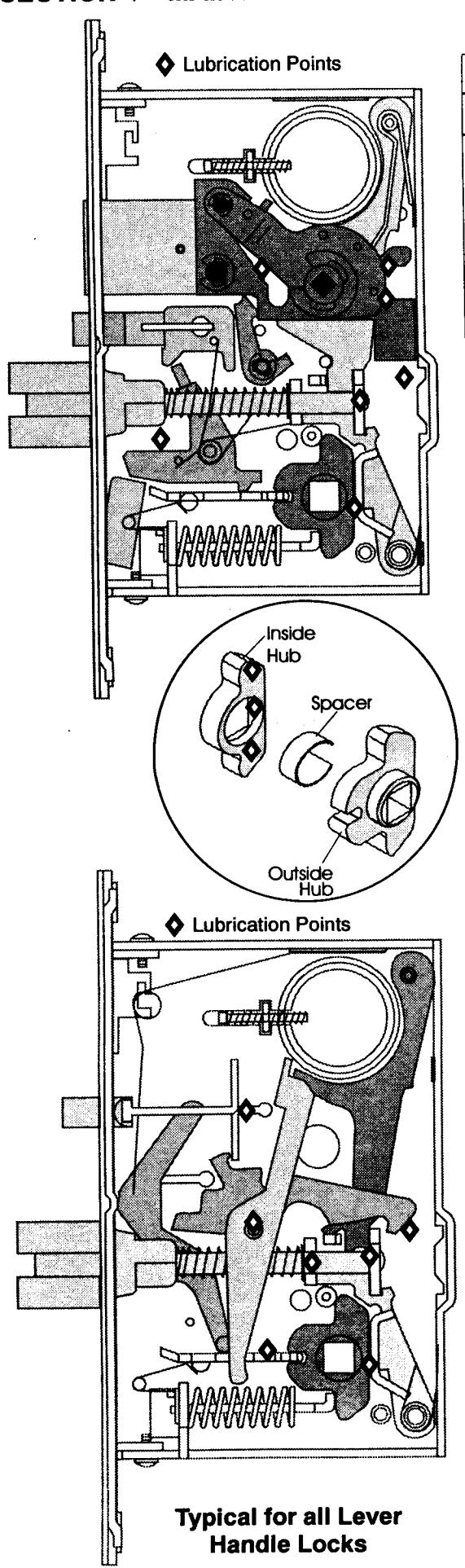
Remove lock from door and remove foreign object from body. Lubricate if necessary. | ||||||
|
Latch bolt hangs
up in lock body. |
Lock body lacks lubrication or lubrication has gummed up with age. | Use penetrating or solvent type lubricant as a cleaning agent to loosen frozen or sticking components. Lubricate with silicone base or Lithium Grease. | |||||
| Cylinder Jams up. | Dirt or other foreign object may be in keyway affecting operation. | Lubricate cylinder with graphite or other non-oily lubricant (such as Lock-EZE ) Do not use oil based lubricants in keyway. | |||||
Yale
Yale Security Inc.