ASSA ABLOY ACCENTRA ElectroLynx Connector System Installation Instructions_80-9460-6013-000
Open the original PDF document
View PDFExit Devices 6100, 6200, 6200(M) Series
Installation Instructions
Table of Contents
| A. ASSA ABLOY Exit Device (ED) with ElectroLynx® for all Electrical Installations1 | |
| B. S Function – Latch Position Monitor | 2 |
| C. B Function – Touchbar Monitor | 2 |
| D. O Function – Trim Monitor | 3 |
| E. P Function – Electric Latch Retraction | 3 |
| F. Mortise Device Trim Safe/Secure | 4 |
| G. Wiring Sample of Mortise Safe/Secure. | 4 |
| H. Safe/Secure and O Function. | 5 |
| I. G Function and O Function | 6 |
| J. G Function – Electric Dogging. | 6 |
| K. Wiring Sample of G Function. | 7 |
| L. Non-ElectroLynx® Door Preparation | 7 |
A. ASSA ABLOY ED with ElectroLynx® for all Electrical Installations
- 1. Mount the exit device per the instruction sheet provided with the device ordered.
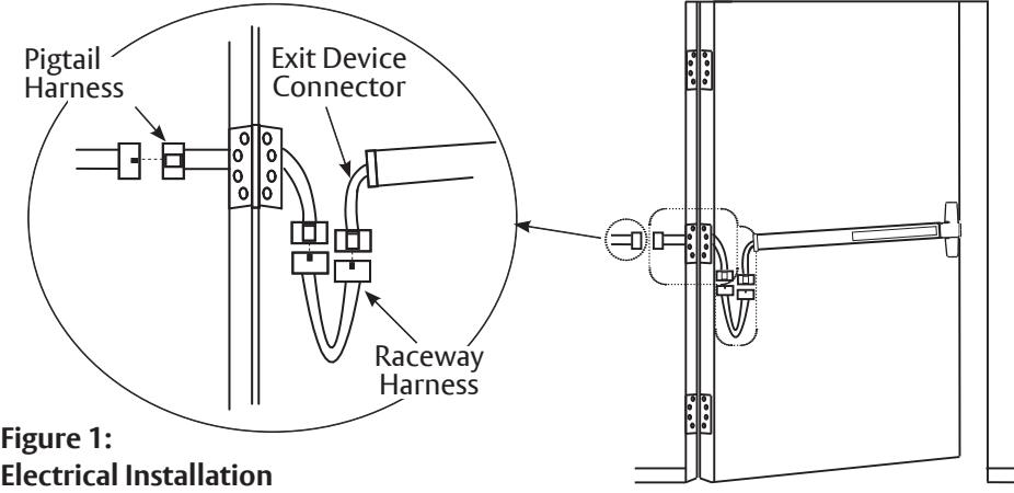
- 2. Plug the exit device connector into the Raceway Harness in the door and feed through 1" (25mm) hole in door. Install rail mounting end clamp bracket with the two (2) screws that are supplied. Install the end cap.
- 3. Plug the Raceway Harness from the edge of the door into the electric hinge connector and feed the wires back through the door preparation. Mount the electric hinge to the door.
- 4. Wire the frame side wires to the wires on the pigtail harness on the hinge as required using the connectors allowed by local code. Plug the pigtail harness connector into the electric hinge connector. Feed the harnesses through the frame preparation and mount the electric hinge.
Note:
- Wiring to pigtail harness is per facility wiring requirement.
- If you do not have an ElectroLynx® System use the related instructions for your system and refer to Section L of this document.
- These instructions detail the installation of each function separately.
- The ElectroLynx® System is easy to install with plug connectors from an electric hinge through the door to the device. The only wiring required, is loose wires on the pigtail harness assembly on the frame side of the electric hinge (included with the ElectroLynx® hinge).
- Combinations of certain switches and monitors can be used.
IMPORTANT: Plug and receptacle connectors mate and lock together. Be sure the connectors plug
into each other with the locking mechanisms aligned. DO NOT FORCE CONNECTORS.
WARNING
This product can expose you to lead which is known to the state of California to cause cancer and birth defects or other reproductive harm. For more information go to www.P65warnings.ca.gov.
WARNING
Attention Installer: Any retrofit or other field modification to a fire rated opening can potentially impact the fire rating of the opening, and ASSA ABLOY makes no representations or warranties concerning what such impact may be in any specific situation. When retrofitting any portion of an existing fire-rated opening, or specifying and installing a new fire-rated opening, please consult with a code specialist or local code official (Authority Having Jurisdiction) to ensure compliance with all applicable codes and ratings.
B. S Function – Latch Position Monitor
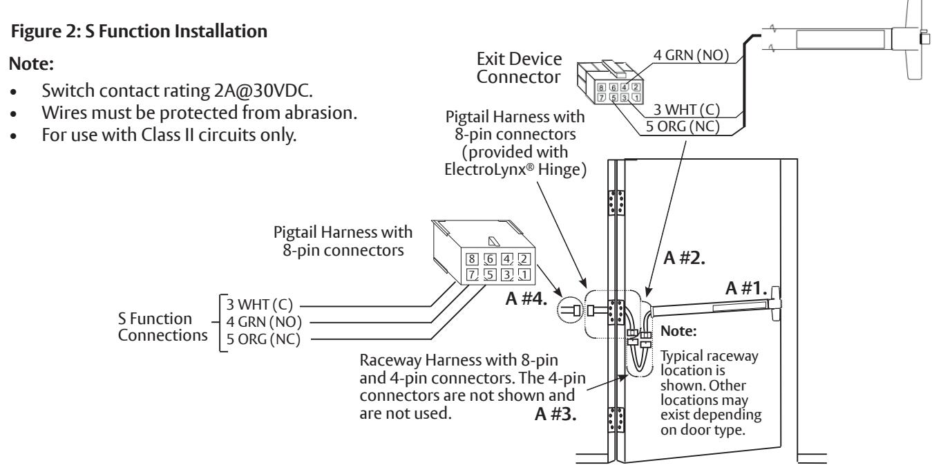
The S Function is a bolt actuated Single Pull Double Throw (SPDT) switch. Refer to Section A and Figure 2 for installing a ASSA ABLOY Exit Device with an ElectroLynx® System for all electrical installations. Numbers 1 through 4 in the figure directly refer to the numbers in Section A.
C. B Function – Touchbar Monitor
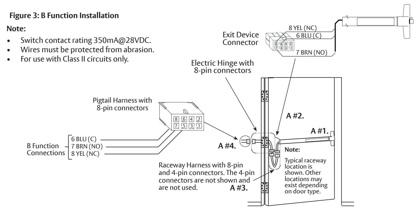
The B Function is a touchbar actuated SPDT switch which indicates egress in progress. Refer to Section A and Figure 3 for installing a ASSA ABLOY Exit Device with an ElectroLynx® System for all electrical installations. Numbers 1 through 4 in the figure directly refer to the numbers in Section A.
Exit Devices
6100, 6200, 6200(M) Series
Installation Instructions
ASSA ABLOY
D. O Function – Trim Monitor
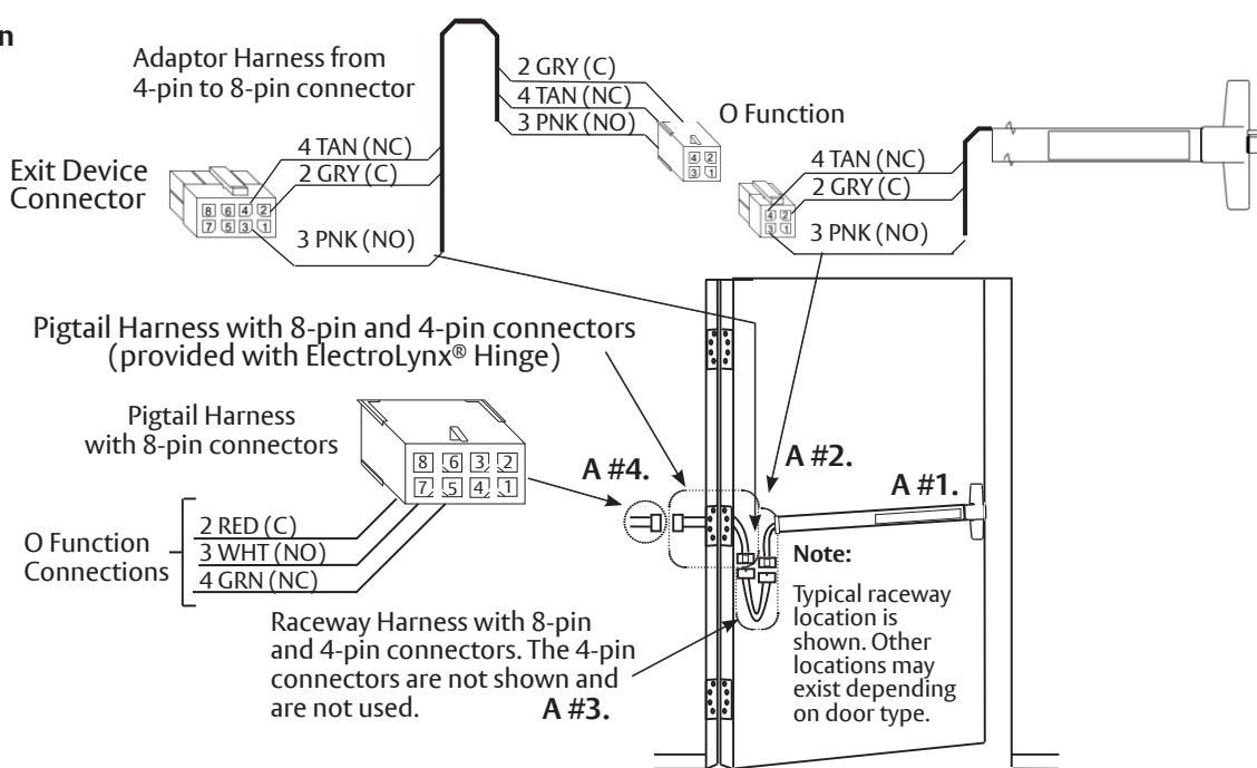
The O Function is a trim actuated SPDT switch. Refer to Section A and Figure 4 for installing a ASSA ABLOY Exit Device with an ElectroLynx® System for all electrical installations. Numbers 1 through 4 in the figure directly refer to the numbers in Section A.
Figure 4: O Function Installation
Note:
- Switch contact rating 350mA@28VDC.
- Wires must be protected from abrasion.
- For use with Class II circuits only.
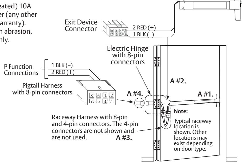
E. P Function – Electric Latch Retraction
The P Function has Electric Latch Retraction. Refer to Section A and Figure 5 for installing a ASSA ABLOY Exit Device with an ElectroLynx® System for all electrical installations. Numbers 1 through 4 in the figure directly refer to the numbers in Section A.
Figure 5: P Function Installation
Note:
- P Function Solenoid (.172A seated) 10A inrush, requires 782 Controller (any other Power Supply voids Device Warranty).
- Wires must be protected from abrasion.
- For use with Class II circuits only.
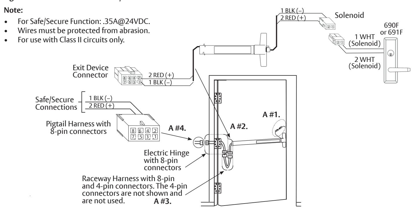
F. Mortise Device Trim Safe/Secure
Refer to Section A and Figure 6 for installing a ASSA ABLOY Exit Device with an ElectroLynx® System for all electrical installations. Numbers 1 through 4 in the figure directly refer to the numbers in Section A. Figure 6 gives a sample of the wiring.
Figure 6: Mortise Device Trim Safe/Secure Installation
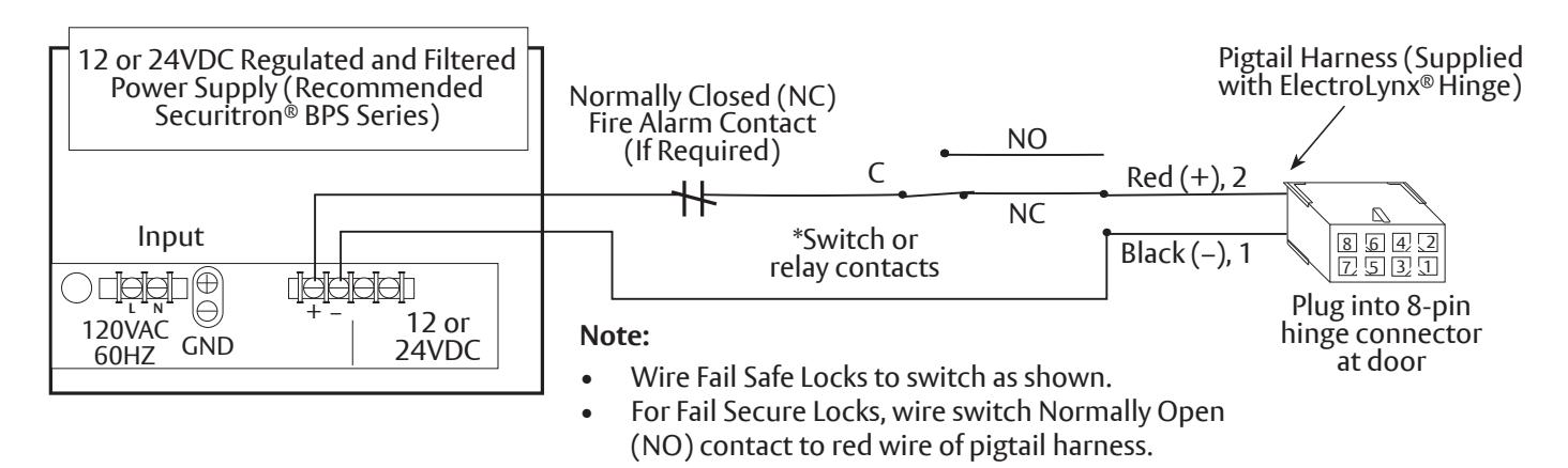
G. Wiring Sample of Mortise Safe/Secure
In Figure 7, the 12 or 24VDC regulated and filtered power supply wiring shows power on and locked in a secure state.
Figure 7: Sample Wiring of Mortise Safe/Secure
Exit Devices 6100, 6200, 6200(M) Series
Installation Instructions

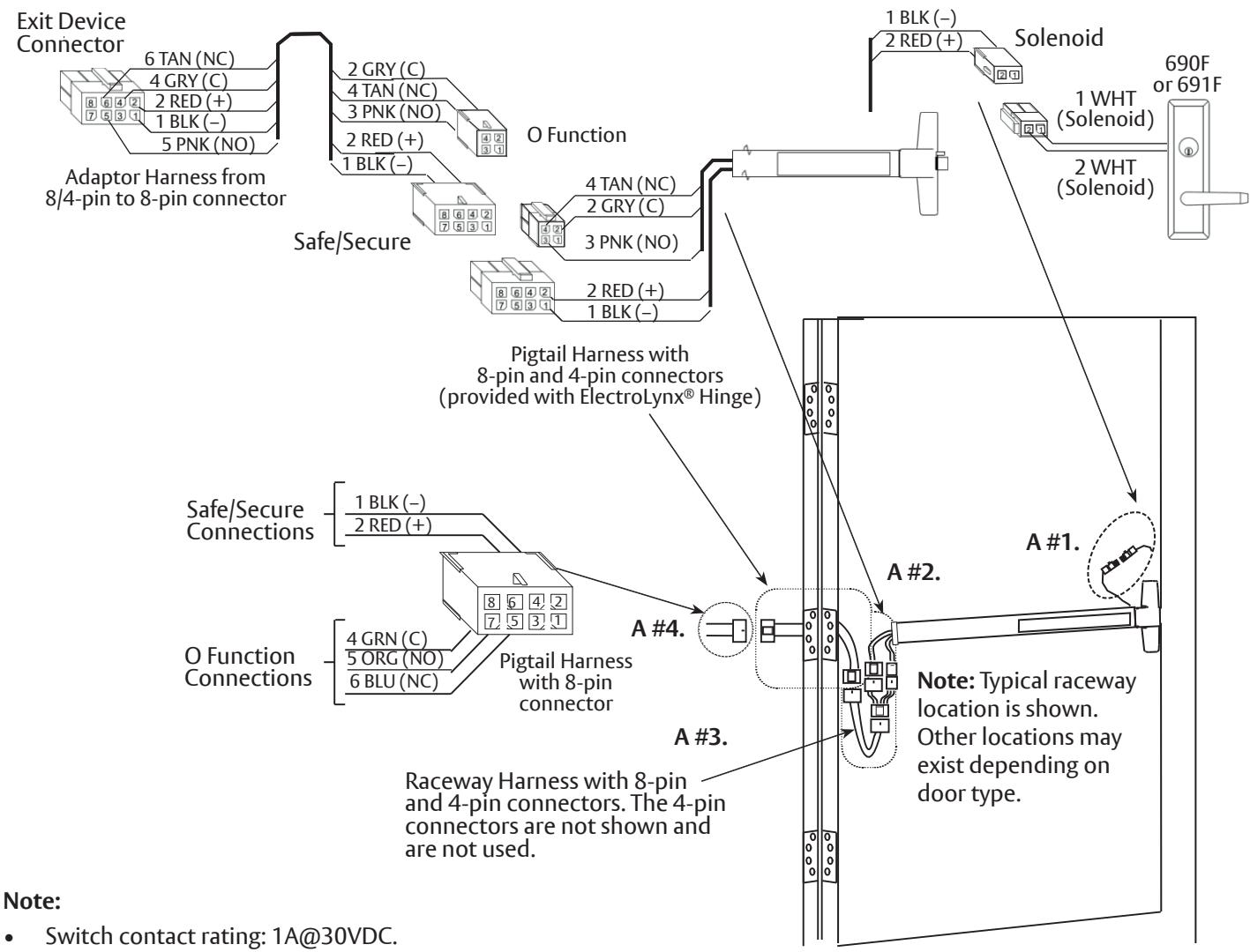
H. Safe/Secure and O Function
Refer to Section A and Figure 8 for installing a ASSA ABLOY Exit Device with an ElectroLynx® System for all electrical installations. Numbers 1 through 4 in the Figure 7 directly refer to the numbers in Section A. Figure 6 gives a sample of the wiring.
Figure 8: Safe/Secure and O Function Installation
- For Safe/Secure Function: .35A@24VDC.
- Wires must be protected from abrasion.
- For use with Class II circuits only.
Exit Devices 6100, 6200, 6200(M) Series Installation Instructions
I. G Function and O Function
Refer to Section A and Figure 8 for Installing a ASSA ABLOY Exit Device with an ElectroLynx® System for all electrical installations. Numbers 1 through 4 in Figure 9 directly refer to the numbers in Section A. Figure 11 gives a sample of the wiring.
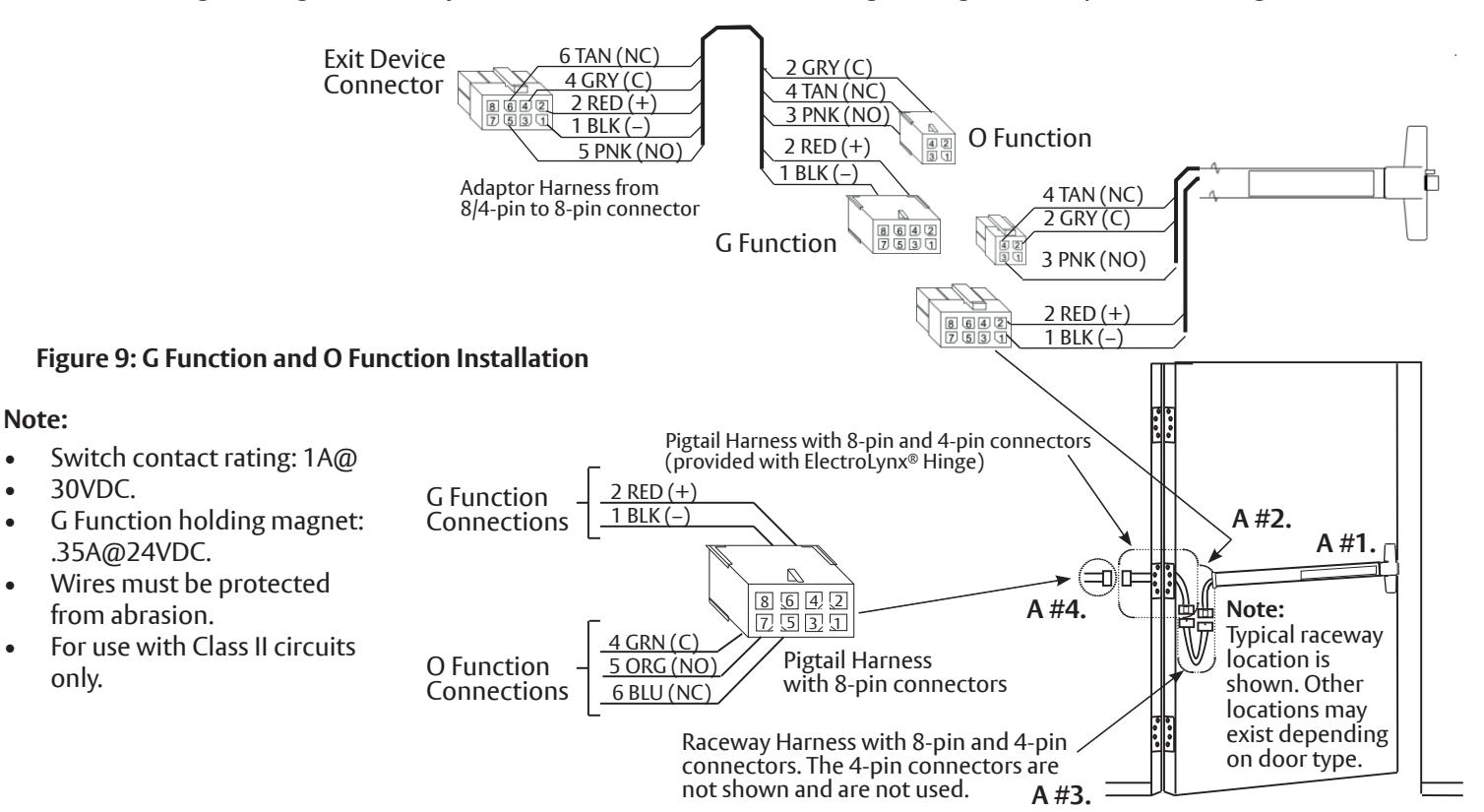
J. G Function – Electric Dogging
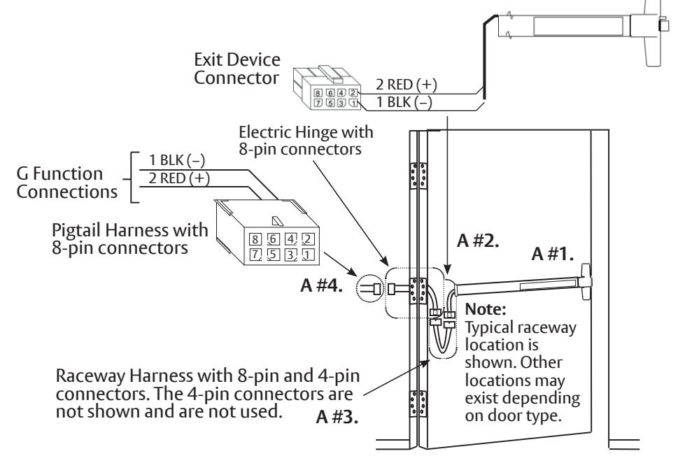
Refer to Section A and Figure 10 for Installing a ASSA ABLOY Exit Device with an ElectroLynx® System for all electrical installations. Numbers 1 through 4 in the figure directly refer to the numbers in Section A. Figure 11 gives a sample of the wiring.
Figure 10: G Function Installation
Note:
- G Function holding magnet: .35A@ 24VDC.
- Wires must be protected from abrasion.
- For use with Class II circuits only.
80-9460-6013-000 12/23
Experience a safer and more open world
1-800-438-1951 • www.assaabloy.com
Exit Devices
6100, 6200, 6200(M) Series
Installation Instructions
ASSA ABLOY
K. Wiring Sample of G Function
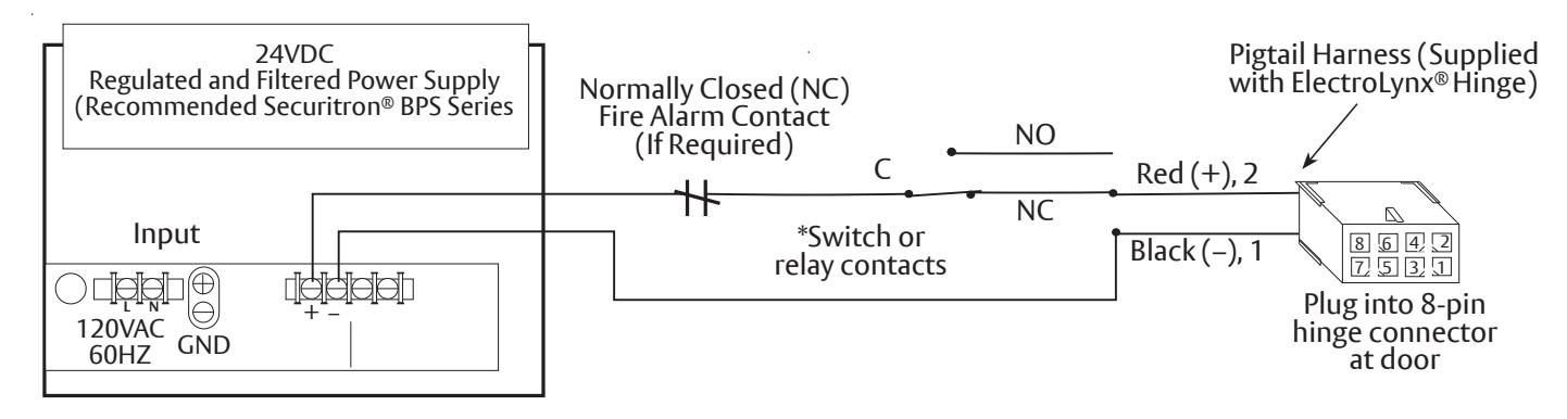
Once wiring is complete, turn the control switch on to apply power to the device. The first depression on the pushpad will retract the latchbolt and hold the pushpad in a dogged position. Fire alarm activation, power interruption or turning the control switch off will release the pushpad and relatch the device (Figure 11).
Figure 11: Sample Wiring of G Function
L. Non-ElectroLynx® Door Preparation
To install a non-ElectroLynx® door, remove the connector at the end of the ASSA ABLOY Exit Device and connect those wires to the incoming wires from the power source using wire nuts, butt splices, etc. (Figure 12).
Note:
- Do not scale drawing.
- LHR Hollow Metal (HM) opening shown. Details are typical for all opening materials (both hands).
- This preparation is an addition to preparation shown on device template.
- See device template to locate centerline of device.
- Shields for wiring access recommended for insulated and composite doors.
- Refer to device instructions with ordered product for door preparation and template information.
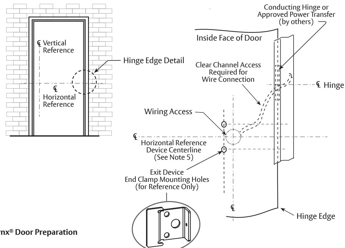
Figure 12: Non-ElectroLynx® Door Preparation