ASSA ABLOY ACCENTRA 8800 Series Mortise Locksets (Knob, Lever, Reflections and Security Trims) Installation Inst…_80-9086-0025-010
Open the original PDF document
View PDF

8800 Series Mortise Lockset Knob, Lever, Reflections® and Security Trims Installation Instructions
- * REMOVING COVER SCREWS VOIDS LOCK BODY WARRANTY
- * USING REFLECTIONS® TRIMS WITH FL LOCKBODIES WILL VOID THE WARRANTY AND SECURITY GRADE.
The following is a step by step approach to installing a mortise lock and trim to both wood and steel doors.
- 1) Determine Hand of Door
- 2) Position Template and Mark Door
- 3) Drill Holes in Door
- 4) Mark Frame for Strike and Mortise Cavities
- 5) Drill Mortise Cavities in Door and Frame
- 6) 8800 Lock Handing Instructions
- 7) Tools Necessary and Preparing Trim for Assembly
- 8) Install Lock (Wood or H.M Door)
- 9) Install Knob or Lever Sectional Trim
- 10) Install Knob or Lever Escutcheon Plate Trim (Thru-bolted)
- 11) Install Knob or Lever Single Operating Trim (Sectional & Escutcheon)
- 12) Install Reflections Sectional Trim 13) Install Reflections Escutcheon Trim
- 14) Install Reflections® 855 Pull Trim
- 15) Installing Thumbturn Assemblies
- 16) Install Visual Occupancy Indicator
- 17) Install Dummy Trim for 838A and 838B
- 18) Install Single Dummy Trim for 838A and 838B
- 19) Install Strike
- 20) Installation Trouble Shooting Tips
1) Determine Hand of Door
Face the door from the outside to determine its hand. Please note the outside is either the key side of an entrance door or the corridor side of a room door. The outside of a single communicating door is the side opposing the hinges. The outside of twin communicating doors is the space between the doors.
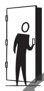
Left Hand Reverse: Hinges on left, opens outward. For handed locks, specify HR.

Left Hand: Hinges on left, opens inward. For handed locks, specify LH.

Right Hand: Hinges on right, opens inward. For handed locks, specify RH.
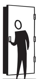
Right Hand Reverse: Hinges on right, opens outward. For handed locks, specify RHR.
2) Position Template and Mark Door
- a. Draw a horizontal centerline for the lock on both sides of door at desired height above finished floor line. Standard height for horizontal centerline is 39-15/16" above finished floor.
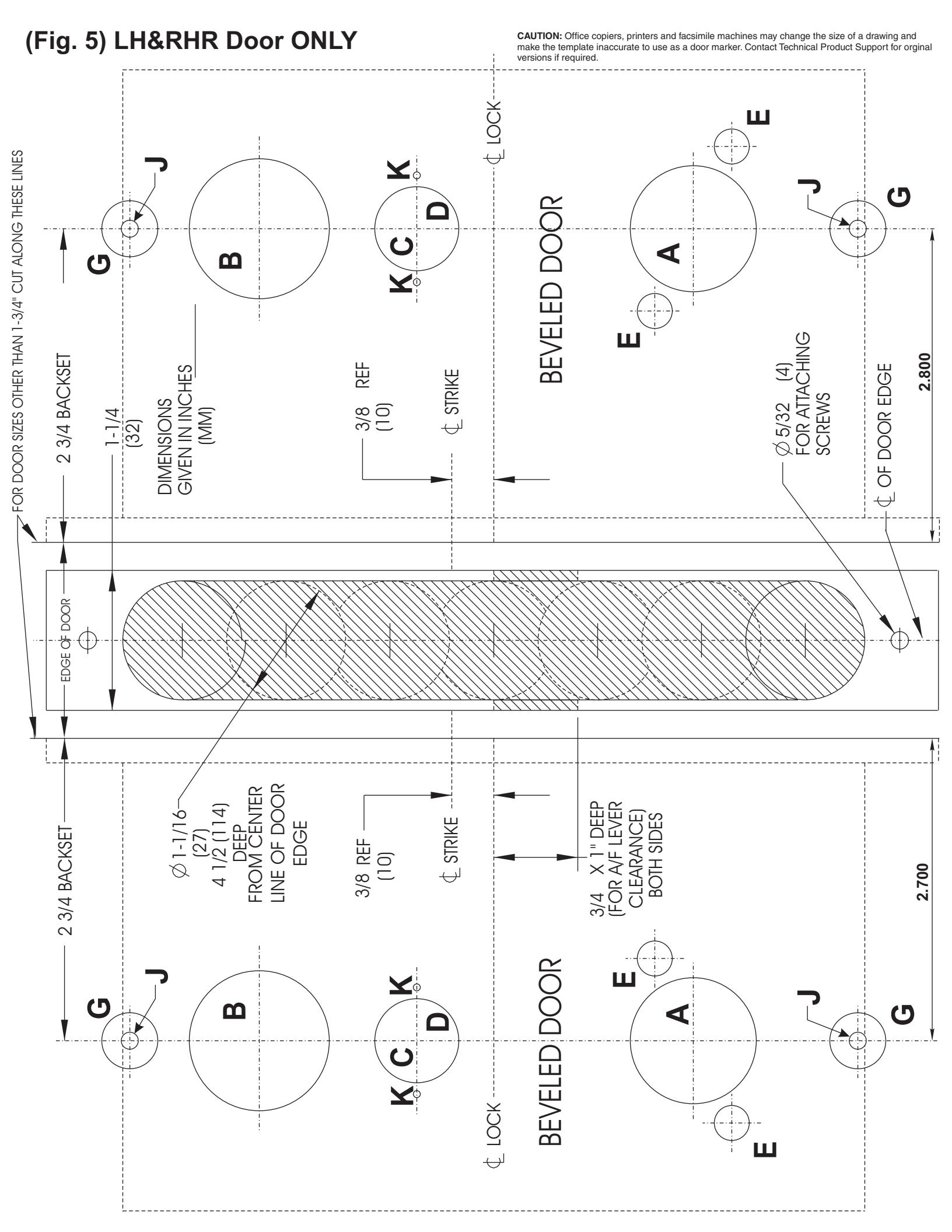
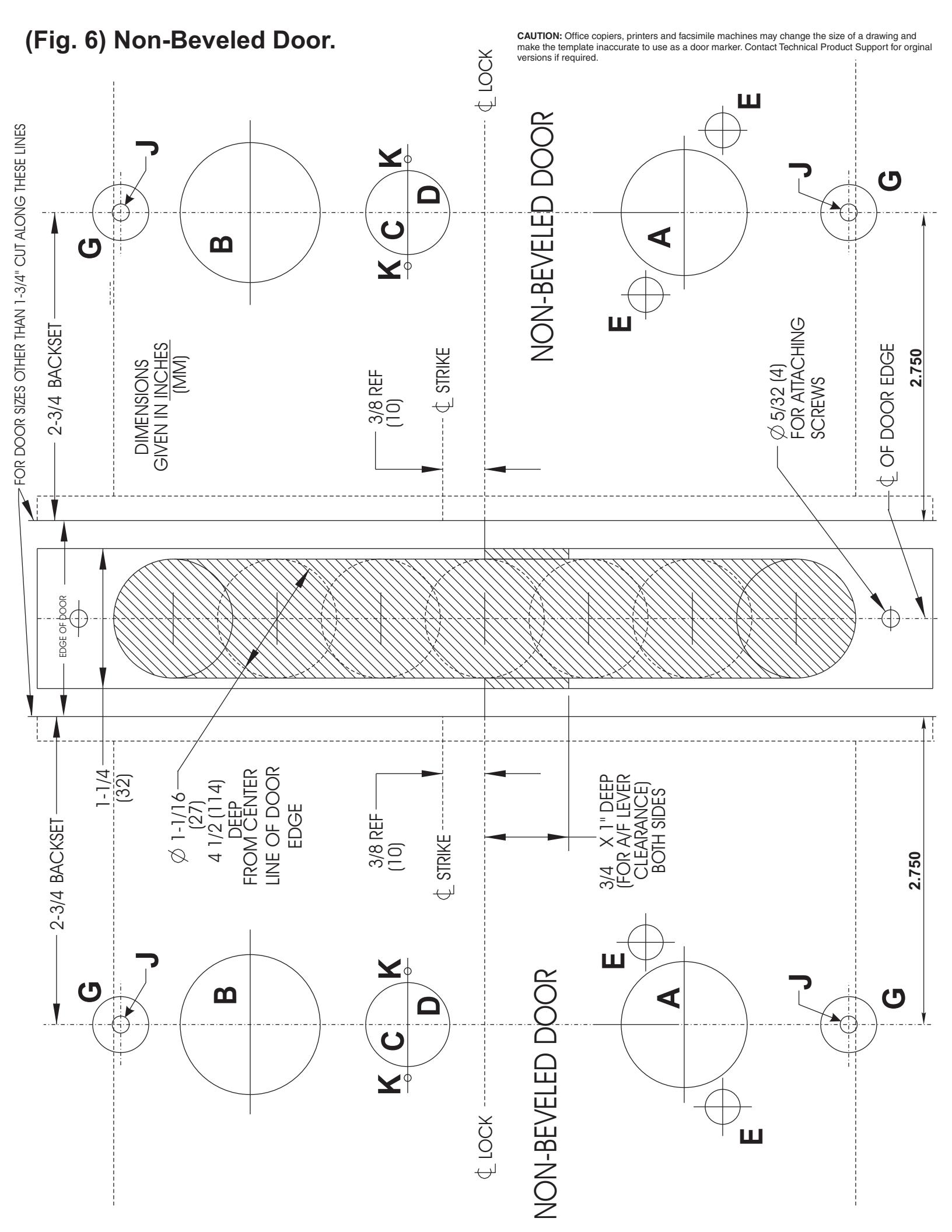
- b. Select template by comparing handing of door to Fig. 4, 5 and 6.
- c. Compare lock function number being installed (See Fig. 3) to determine the holes to be marked.
- d. Position the installation template on the door so that the horizontal centerline lines up with the horizontal line on the door. Mark the holes to be drilled using a scribe, center punch, or nail on the inside and outside of door. To avoid shifting of the template, it may be taped to the door during this step.
- e. On the edge of the door mark the holes to be drilled for the mortise cavity and armor front attaching screw holes.
3) Drill Holes in Door
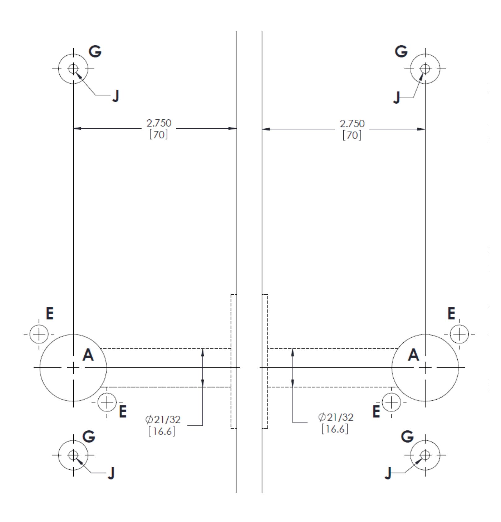
Bore marked lock trim holes (steps 2d and 2e). To avoid splintering wood, bore thru holes from both sides of door. For hole sizes refer to hole chart. Note: Hole "A" diameter is different for FL, RL & SL Applications.
4) Mark Frame for Strike Mortise Cavities
- a. Mark vertical position of strike on jamb using the reference centerline on installation template (see Fig. 4, 5 or 6).
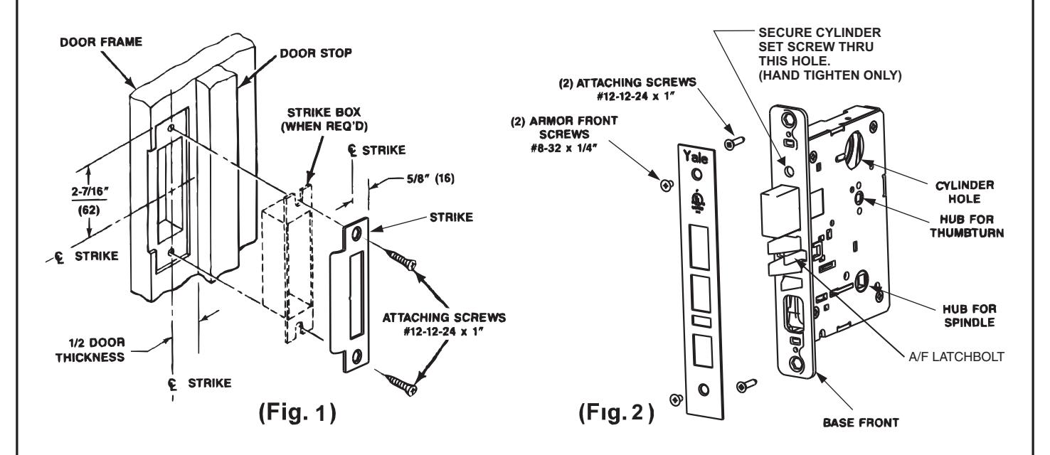
- b. Mark location of strike lip. To locate horizontal centerline of strike, take half the door thickness PLUS the thickness of silencer (if used). Use this dimension to locate the strike centerline from the doorstop. (See Step 19, Fig. 1) (FIRST DETERMINE IF SILENCERS ARE TO BE USED)
5) Drill Mortise Cavities in Door and Frame
- a. Mortise door edge for lock body. Drill pilot holes for attaching screws.
- b. Slide lock body into cavity with armor front attached. Align armor front with top mark. Use lock front as template. Mark outline.
- c. Mortise door edge for lock front (7/32") deep.
- d. Mortise jamb for strike (3/32" deep). Be sure to mortise 1" (25mm) deep to accommodate lock bolts or strike box if used. (See Step 19, Fig. 1)
Note: Before installing lock, prepare door trim per sections 8, 9, 10, 11, 12, 13, or 14.
6) Handing Instructions
HANDING THE LATCHBOLT
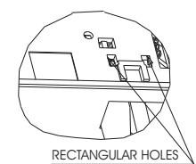
- a. Locate and depress spring plate mechanism in one of the rectangular holes.
- b. While depressing spring plate pull latchbolt head.
- c. Rotate head for desired handing.
- d. Push head into lockbody until secured.
- e. Operate several times to insure operation.
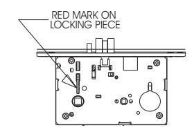
HANDING THE HUBS (LEVER OPERATION)
- a. Locate RED MARK on locking piece.
- b. Push Toggle Button slide away from "square spindle hole"
- c. With blade screw driver push RED MARK on side nearest "square spindle hole"
- d. RED MARK indicates Locked side!
7) Tools Necessary and Preparing Trim for Assembly
Tools necessary:
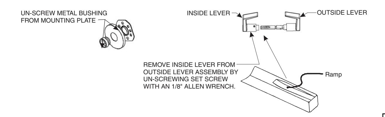
• Standard #2 Phillips Screw Driver • Standard 1/8 inch Allen Wrench • Wrench (flat stamping provided)
Warning: . DO NOT TIGHTEN SCREWS WITH A BATTERY POWERED SCREWDRIVER, HAND TIGHTEN ALL SCREWS
2
8) Install Lock (Wood or H.M. Door)
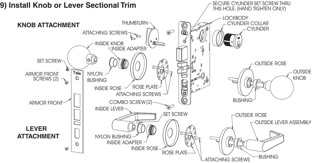
Insert lock body into cavity in door and secure base front with two #12 combination attaching screws. Make sure lock is positioned in cutout properly. Note: Installation may require leaving #12 combination screws loose until trim and cylinder are assembled in lock body.
IMPORTANT NOTE:
Before mounting the Outside Lever Handle on the door back off the inside spindle (the spindle with ramp 1 turn from outside spindle). Be sure that the ramp aligns with set screw in Inside Lever Handle. This must be done to allow proper function of the lock body.
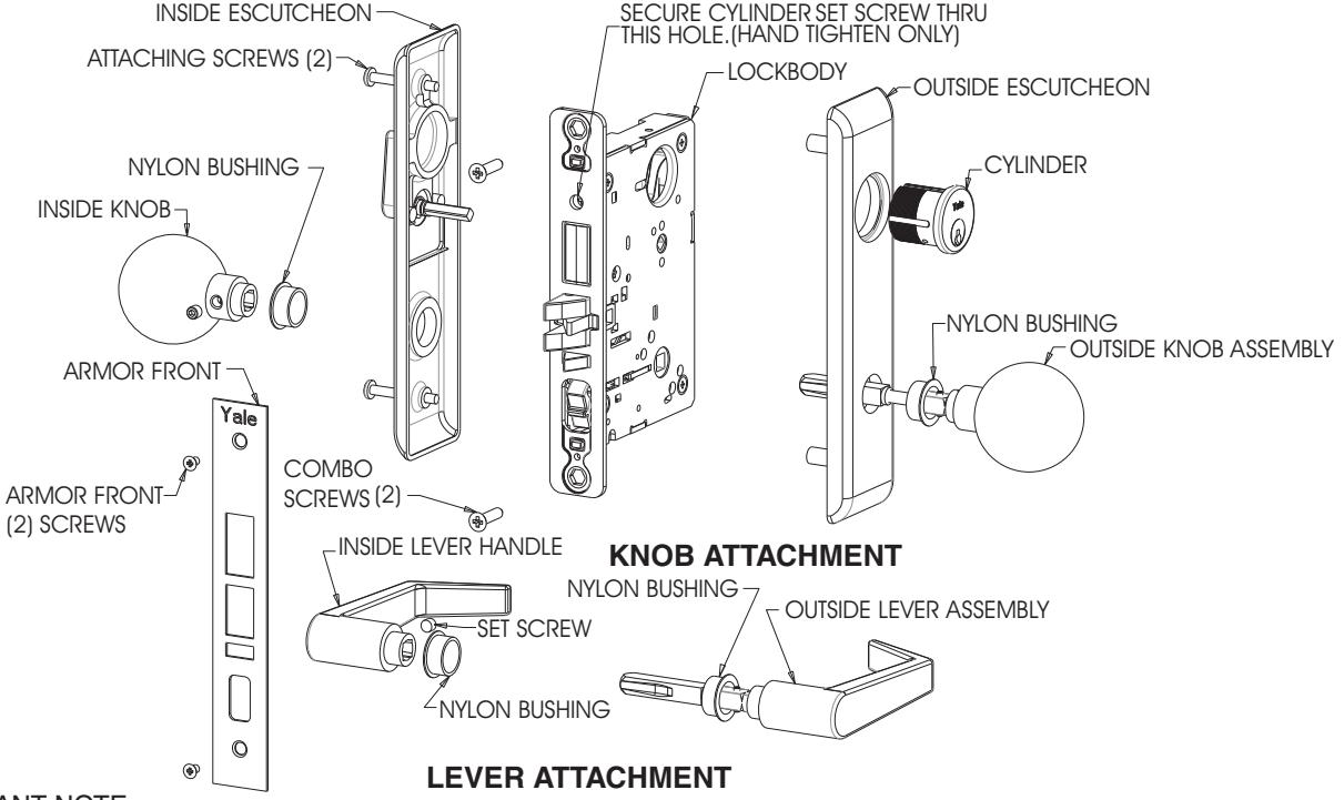
10) Install Knob or Lever Escutcheon Plate Trim (Thru-Bolted)
IMPORTANT NOTE:
3 Before mounting the Outside Lever Handle on the door back off the inside spindle (the spindle with ramp 1 turn from outside spindle). Be sure that the ramp aligns with set screw in Inside Lever Handle. This must be done to allow proper function of the lock body.
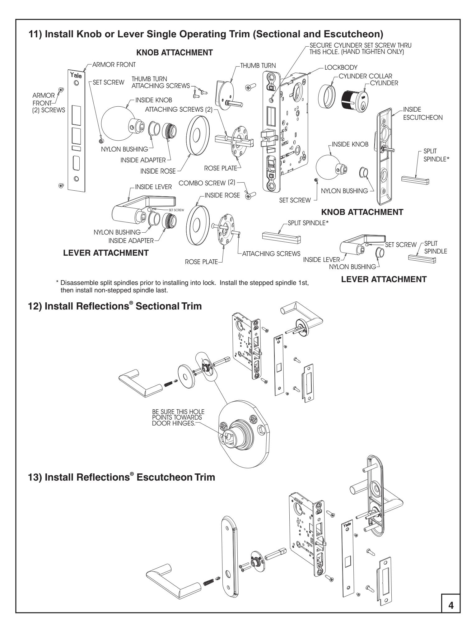
14) Install Reflections 855 Dummy Trim ®
- a. Lever height should be at 39-15/16" from finished floor.
- b. Before securing mounting plate assembly to door, place lever on mounting plate assembly (with set screw) and align on door so lever is parallel to floor. Mark screw hole locations.
15) Installing Thumbturn Assemblies
To install the Thumbturn Assembly on the door:
- a. Drill holes indicated for the function to be installed.
- b. Install the lockbody in the mortise pocket. Align the Thumbturn Shaft thru hole D and into the square hub in the lockbody.
- c. Position the thumbturn mounting plate so the attaching screw holes are horizontal to the floor.
- d. Mark the holes with a punch and remove thumbturn assembly.
- e. Drill the marked holes with a 1/16 Dia. drill bit. "
- f. Re-install the thumbturn shaft in the square hole of lockbody.
- g. Install and tighten attaching screws.
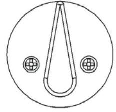
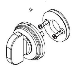
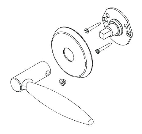
Reflections Thumbturn Assembly and Coin Turn Assembly ® SEE TEMPLATE FOR HOLE LOCATION
16) Visual Occupancy Indicator
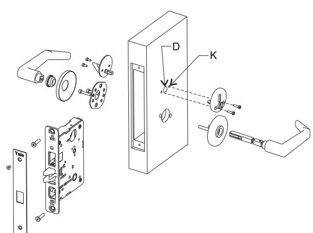
To install the Visual Occupancy Indicator on the outside of the door drill holes D and K. It is best to drill hole D first, then install lock and trim and drill the 2 (K) holes while indicator is in position.
5
17) Install Dummy Trim for 838A and 838B
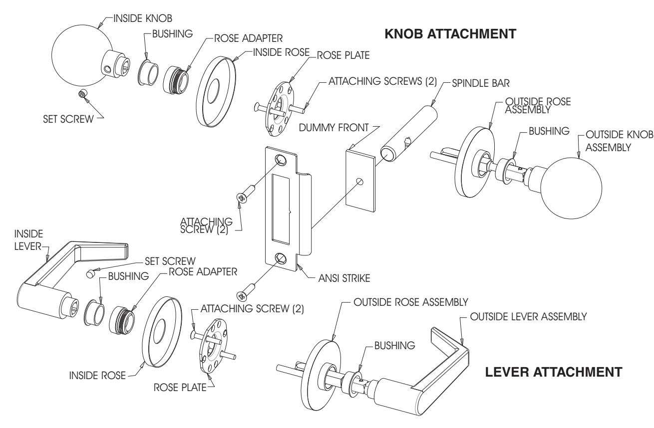
18) Install Single Dummy Trim for 838A and 838B
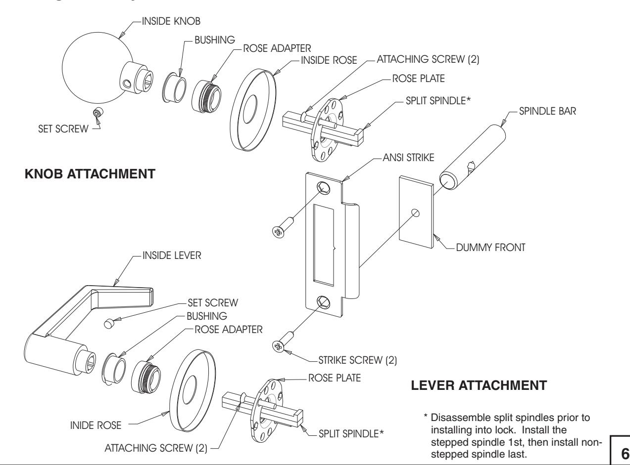
19) Install Strike
Attach strike to jamb using two #12 combination attaching screws. (See Fig. 1)
|
20)
Installation Trouble Shooting Tips |
||||
|---|---|---|---|---|
| * | ||||
* Please note: Disassembling lock body will void warranty.
| Hole Size Chart | |||||||
|---|---|---|---|---|---|---|---|
| Size | Used For | ||||||
| Hole | H.M. | Door | Wood Door | Used For | |||
| A | FL |
1-1/8" Dia
(29) |
1-1/8" Dia
(29) |
Knobs and | |||
| SL |
1-7/8"
(48) |
1-7/8"
(48) |
Levers | ||||
| в |
1-1/4"
(32) |
1-1/4"
(32) |
Cylinder | ||||
| O |
3/4" Dia
(19) |
3/4" Dia
(19) |
Thumbtum or
Emergency Key |
||||
| D |
3/4" Dia
(19) |
3/4" Dia
(19) |
Hotel Indicator
and Visual Indicator |
||||
| E |
5/16"
(8) |
5/16"
(8) |
Rose | ||||
| For Thu | ımbturn atta |
Standard
Thumbturn Reflections Thumbturn & Coin Turn Assemblies |
|||||
| G |
1/2" Dia
(13) |
1/2" Dia
(13) |
Escutcheon Plate
Thru-Bolted |
||||
| J |
.152" Dia
(3.9) #24 Drill |
11/64 x 1 Dp
(4.4 x 25) C'bore 1/2 x 1/8 Dp. (13 x 3) |
Surface
Escutcheon Plate Attaching Screws |
||||
| К |
.116" Dia
(2.9) #32 Drill |
1/16" Dia
(1.6) |
Visual
Indicator |
||||
| See section 16 for details. | |||||||
HOLE CHART FOR 838A AND 838B
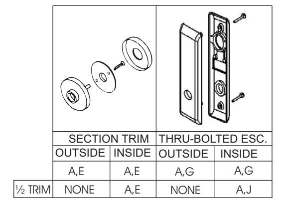
Note: When installing lock functions with thumbturn see step 15 for hole placement.
HOLE CHART 8800 LOCK FUNCTION (KNOB, FL, *RL and SL) SECTION TRIM THRU-BOLTED ESC OUTSIDE INSIDE OUTSIDE INSIDE 8801 8870DT 8871DT 8872DT 8880 A,E A,E A,G A,G 8881 8885 836A&B 838A&B 8802 A,C,E,F A,C,E,F A,C,G A,C,G 8805 8807 A,B,G A,G A,E 8808 A.B.E 8824 8831 8890 A,B*,G A,B*,G A,B*,E A,B*,E 8891 8808-2 8811-2 8812-2 8817-2 8830-2 A.B.E A,B,E A.B.G 8860-2 A,B,G 8894-2 8895-2 8896-2 8897-2 8898-2 8899-2 8820 A,B,D,E A,C,E,F A.B.D.G A,C,G 8827 8809 8822 8832 8847 A,B,E A,C,E,F A,B,G A,C,G 8860 8861 8867 8896 8897 8898 8899 8813ST С B, G C, G 8815 NONE NONE 8828 ΑF Δ.Ι* 8833 B ONL' A,E B ONLY A.J* 8823 A,B,E A,B,G NONE G 8829 ВС B G B. C. G 8813ST-2 В 8814 В NONE B. G G В B, G B, G В 8833-2 8835 A,E,*** A G ** A,C,G A,C,E,F 8862 A,B,E A,B,G 8834-2 8864 A,B,C,E A,C,E,F A.B.C.G A,C,G
Figure 3
CAUTION: Office copiers, printers and facsimile machines may change the size of a drawing and make the template inaccurate to use as a door marker. Contact Technical Product Support for orginal versions if required.
Yale Locks & Hardware
100 Yale Avenue, Lenoir City, TN 37771 • Product Support Tel 800.438.1951 • Fax 800.338.0965 • www.yalelocks.com Yale Locks & Hardware is a division of Yale Security Inc., an ASSA ABLOY Group company.
Yale® and Reflections® are registered trademarks of Yale Security Inc., an ASSA ABLOY Group company. Other products' brand names may be trademarks or registered trademarks of their respective owners and are mentioned for reference purposes only. These materials are protected under U.S. copyright laws. All contents current at time of publication. Yale Security Inc. reserves the right to change availability of any item in this catalog, its design, construction, and/or its materials. Copyright © 2010, Yale Security Inc., an ASSA ABLOY Group company. All rights reserved. Reproduction in whole or in part without the express written permission of Yale Security Inc., an ASSA ABLOY Group company is prohibited.
YALE, with its unique global reach and range of products, is the world's favorite lock.
ASSA ABLOY is the global leader in door opening solutions, dedicated to satisfying end-user needs for security, safety and convenience.
8
(Fig. 7) 838A AND 838B KNOB AND LEVER DUMMY TRIM
CAUTION: Office copiers, printers and facsimile machines may change the size of a drawing and make the template inaccurate to use as a door marker. Contact Technical Product Support for orginal versions if required.