ASSA ABLOY ACCENTRA 7220 Series CVR Exit Device Instructions_80-9472-0020-000
Open the original PDF document
View PDFASSA ABLOY
Installation Instructions
M WARNING
Attention Installer: Any retrofit or other field modification to a fire rated opening can potentially impact the fire rating of the opening, and Assa Abloy makes no representations or warranties concerning what such impact may be in any specific situation. When retrofitting any portion of an existing fire-rated opening, or specifying and installing a new fire-rated opening, please consult with a code specialist or local code official (Authority Having Jurisdiction) to ensure compliance with all applicable codes and ratings.
1-800-438-1951 • www.assaablov.com
Experience a safer and more open world
ASSA ABLOY
Concealed Vertical Rod Exit Device
7220
Installation Instructions
Maintenance
- Periodically remove covers and coat mechanisms with a silicone base lubricant. This is particularly required in corrosive environments for proper product function.
- Check mounting fasteners periodically. Retighten if found loose. Apply screw locking compound (available at automotive part stores) or change part fasteners if screws continue to back out.
- Periodic checks (and adjustments) of strikes are required to compensate for changes in the opening (e.g. door sagging).
To Change Hands
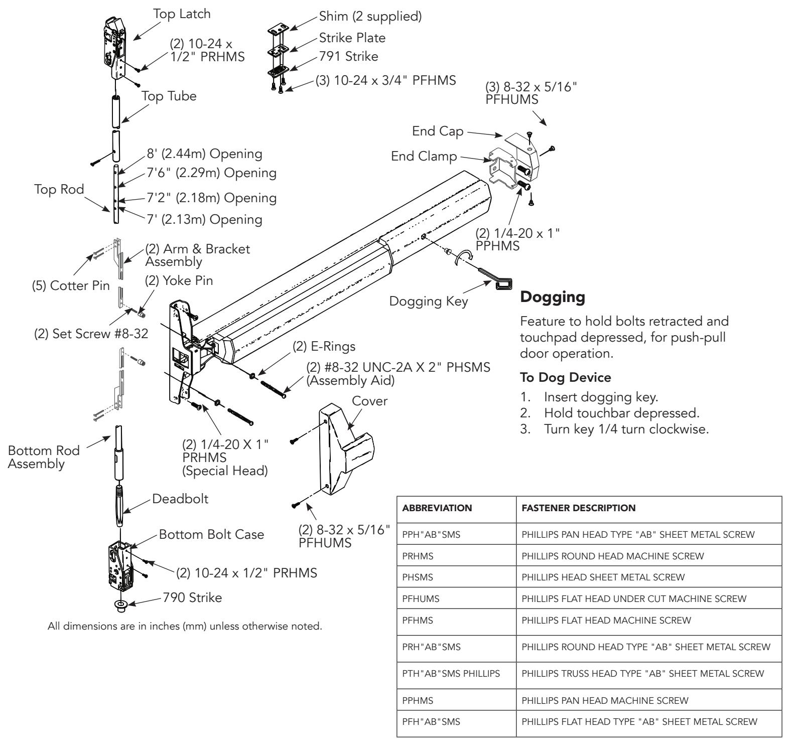
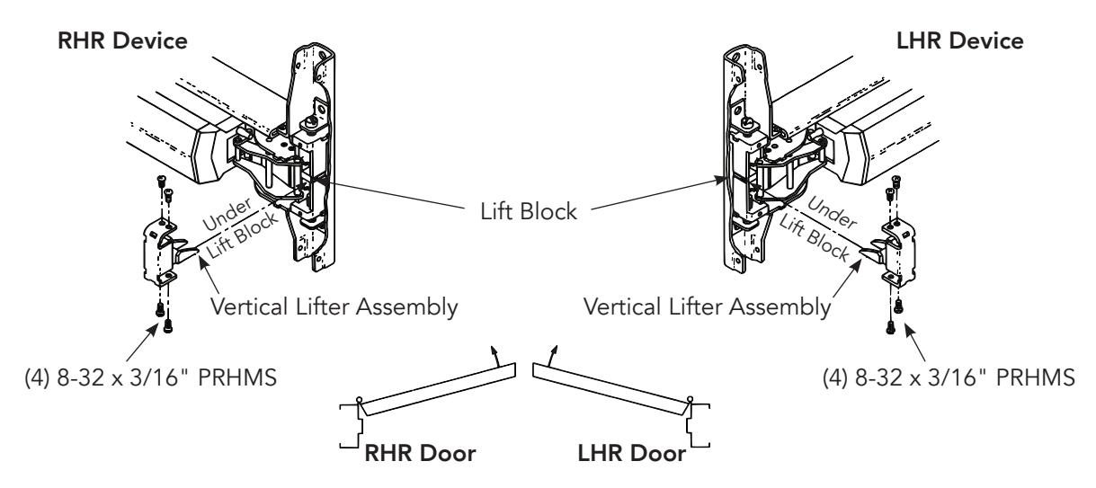
- 1. Remove four (4) screws and Vertical Lifter Assembly.
- 2. Rotate device to opposite hand (180 degrees).
- 3. Insert Lifter Assembly under Lift Block and re-install screws.
Check Before Starting
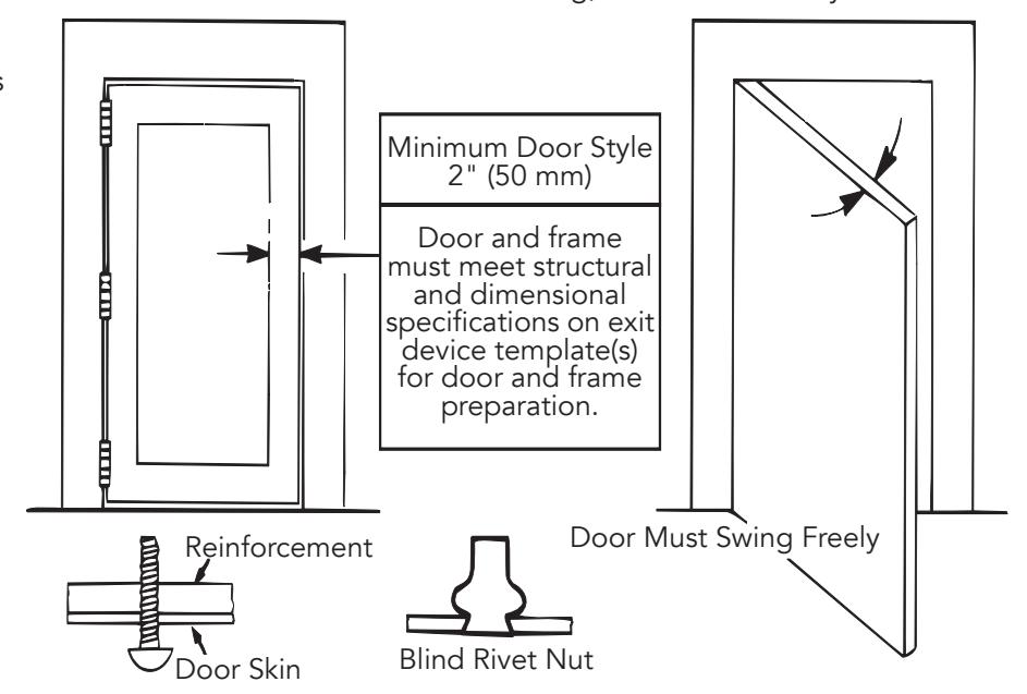
Unreinforced Doors or Frames
Doors and Frames with walls having a structural thickness (metal skin plus reinforcement or solid hardwood) to engage less than (3) full screw threads are considered unreinforced.
Unreinforced Doors: Use SNB (sex nuts and bolts).
Unreinforced Frames: Use Blind Rivet Nuts.
Recommended fasteners for unreinforced openings are not necessarily supplied by ASSA ABLOY.
The device must seat flush on the door surface. To clear raised molding, consult the factory.
Installation Instructions
1. Mark Door
Single Door or Pair without Mullion
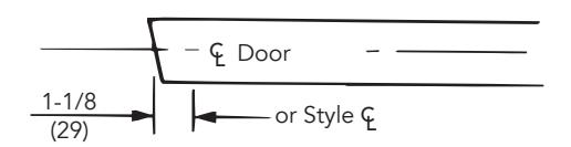
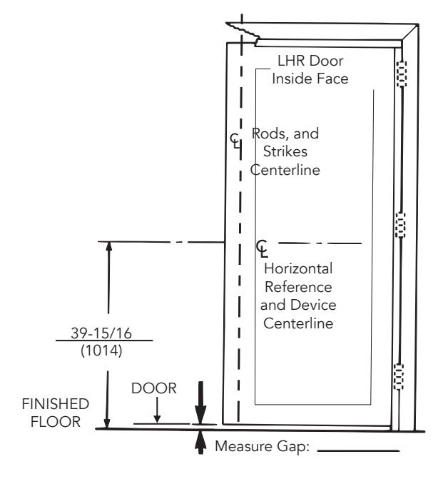
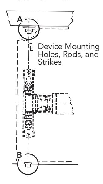
Locate and Mark Horizontal Reference and Rod and Strike Centerlines as shown. LHR door shown, preparation is typical for both door hands.
Note: The Bottom Bolt will retract to 1/8" (3mm) above the Floor Strike. Floor covering in the door path must be laid out accordingly.
2. Prepare Door, Frame, and Sill
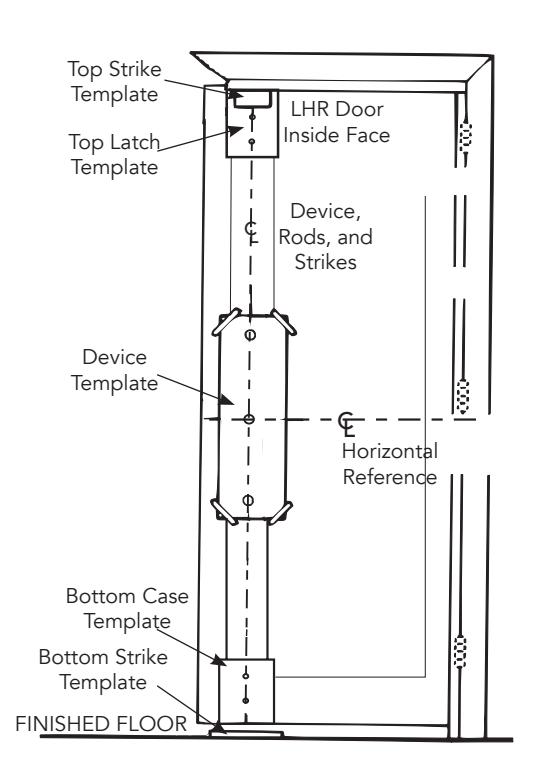
- A. Locate the Device Template aligning RODS and STRIKES CENTERLINE and HORIZONTAL REFERENCE CENTERLINE on the door and template. Tape the template to the door face.
- B. Extend the centerline of Rod and Strikes from the Device Template to door top and bottom, on the door face.
- C. Locate Top Latch/Strike, Bottom Case and Bottom Strike templates aligned on centerline of Device, Rods, and Strikes on door. Tape the templates in place and mark the holes.
- D. Locate and tape the Trim Template to door (See the instructions packed with Trim).
- E. Mark and prepare holes:
Device: Each (2) 1/4-20 Machine Screws (Metal reinforced door only.) or (2) 3/8" (10mm) Dia. Sex Nuts & Bolts
Top Latch Case & Bottom Bolt Case: Each (2) 7/32" (5.5mm) Dia. Holes (Door Inside Face Only)
Top Strike: (2) 10-24 Machine Screws or (2) #10 Wood Screws
Note: Third screw MUST ONLY be used to lock Strike in fi nal position (Section 8, Step 3).
Bottom Strike: 5/8" (16mm) dia x 3/4" (19mm) deep hole
ASSA ABLOY
Concealed Vertical Rod Exit Device
7220
Installation Instructions
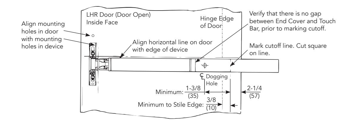
3. Size Device
Device must be field cut to size unless the standard opening and the device are 36" (0.91m) or 48" (1.22m).
4. Rod Assembly & Preliminary Adjustment
- A. Remove the door from the opening. Set flat, device side up. (Do not hang the door until Section 8 of device installation sheet.)
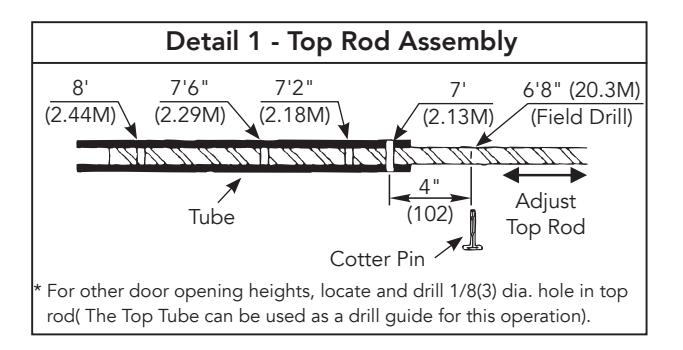
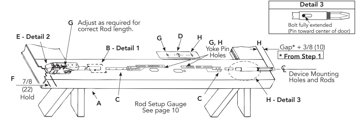
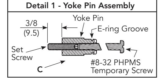
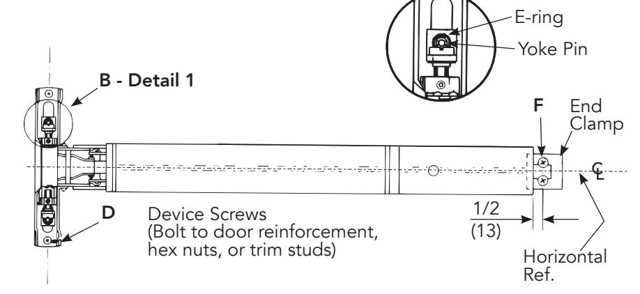
- B. Set length of Top Rod Assembly (see Detail 1).
- C. Connect Top & Bottom Rods to Arm/Bracket Assemblies. (2 Cotter Pins each)
- D. Align Rod Setup Gauge over Device Cutouts and Centerlines. Tape Gauge to door face.
- E. Connect Top Latch to Rod Assembly.
- F. Set Top Latch and Rod Assembly in place on the door. Maintain 7/8"(21) location from top as shown.
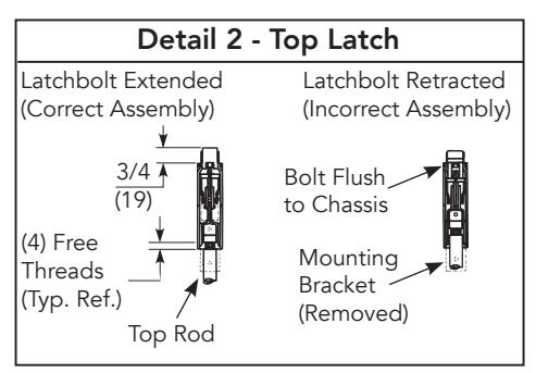
- G. Align Yoke Pin holes in Arm and Bracket Assembly with Alignment Hole in Rod Setup Gauge. Adjust top Latch and Rod Assembly for proper alignment. Latchbolt must be extended. (See Detail 2).
- H. Thread bottom bolt into Bottom Rod Assembly. Set Bottom Bolt Rod Assembly in place on door. Align Yoke pin hole in the Bottom Arm and Bracket Assembly with Alignment Hole in Rod Setup Gauge. Adjust Bottom Bolt until it protrudes 3/8"(10) + the gap from Section 1, past the bottom edge of door. Make sure the Bottom Bolt is fully extended, (See Detail 3).
7220
Installation Instructions
5. Install Rods
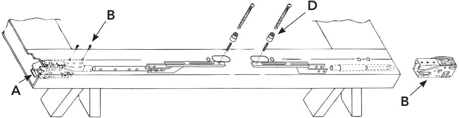
- A. Slide the Rod Assemblies into the door.
- B. Attach Top Latch and Bottom Bolt Case with (4) #10-24 X 1/2" PFHMS.
- C. Thread Set Screw into Yoke Pins (Insert With Hex Socket End Inside Pin). Thread #8-32 X 2" PHPMS Screws into slotted end of Yoke Pins, until seated to Hex Head Set Screw. (See Detail 1.)
- D. Install (2) Yoke Pin Assemblies into the Arm and Bracket Assemblies.
Check action: Top rod should move freely until latchbolt stays retracted and back after bolt release. Bottom rod should move freely up and
down at least 9/16" (14).
ASSA ABLOY
6. Install Device
- A. Mount trim (follow instructions packed with trim).
- B. Seat device in place using the Temporary Screws from Section 5 to position the Yoke Pins to the latch head. Install E-Ring into Yoke Pin Grooves. (See Detail 1).
- C. Fasten device Latch Head (2) 1/4-20 PPHMS or 3/8" (10) dia. SNB.
- D. Remove Temporary Screws.
- E. Center end of device on horizontal reference line of door. Using the End Clamp as a template, locate the end clamp mounting holes.
- F. Prepare end clamp holes and mount End Clamp using (2) 1/4-20 PPHMS or 3/8" (10) SNB.
7. Install Strikes
Detail A (Upper Strike)
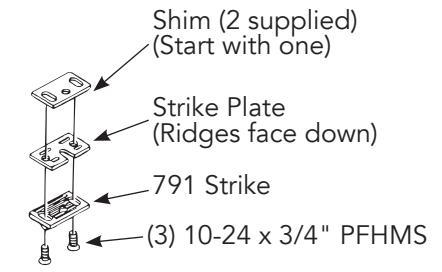
Note: The third screw must be installed after the device is adjusted and working properly. (See Section 8, Step 3).
Detail B (Bottom Stike)
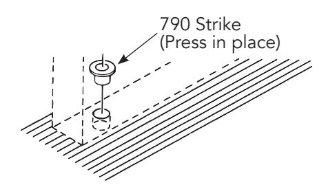
Note: The bottom bolt will retract to 1/8" (3mm) above the floor strike. The floor covering in the door path must be laid out accordingly.
80-9472-0020-000 10/23
Experience a safer and more open world
1-800-438-1951 • www.assaabloy.com
7220
Installation Instructions
8. Complete the Installation
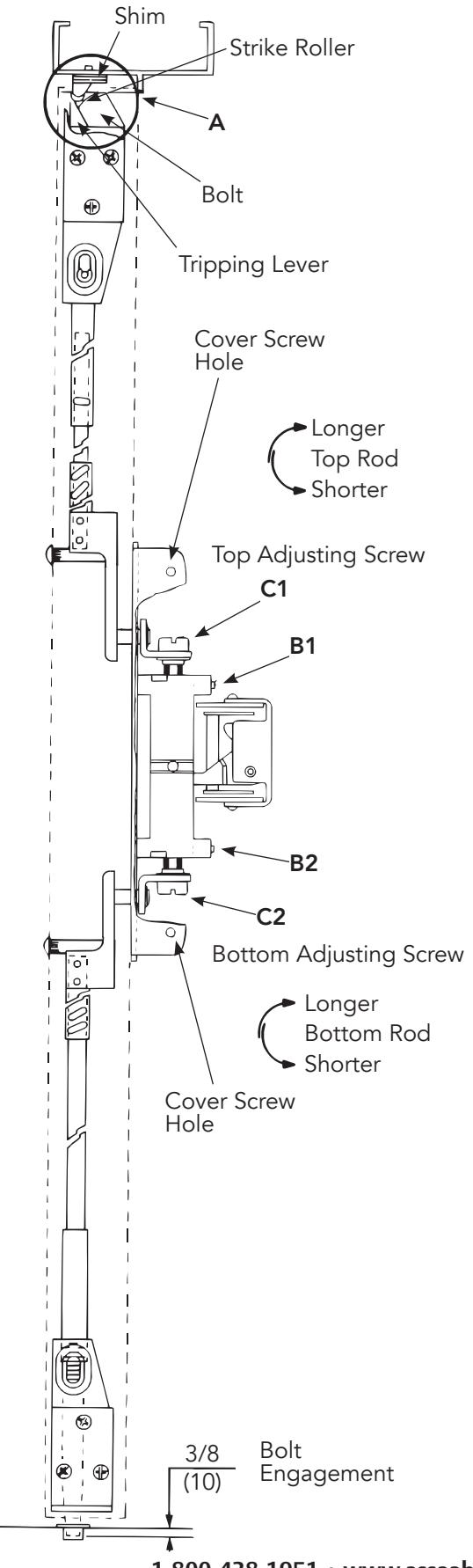
A. Rehang the door plumb and true to the opening. Set the strike roller between the tripping lever and the bolt. DO NOT PRELOAD THE BOLT. Shim the strike as needed.
Note: Rods should move freely inside the door. Bolts extend automatically and should deadlock when the door closes and the top strike hits the tripping lever. The top bolt should retract fl at. The bottom bolt should travel 1/2" and engage 3/8" into the strike in the down position, without dragging on the fl oor surface in the up position.
Test the device action by touchbar, by trim, and by dogging. Adjust as needed.
-
B. Rod Adjustment for Proper Bolt Throw
- 1. Use a 3/32" hex wrench to loosen set screws B1 and B2.
- 2. Adjust the top rod fi rst with adjusting screw C1. With the device in dogged position (panic devices) or the touchbar fully depressed (fi re devices), adjust the top rod so that the top latchbolt is fl ush and the hold back feature is engaged. Lengthen the top rod an additional 1/2 turn for proper latchbolt positioning.
Note: If the adjusting screws bottom out before proper device operation, the door and device must be removed so larger adjustments may be made by threading the rod in or out, or by moving the cotter pin to adifferent hole in the rod (See "4. Rod Assembly & Preliminary Adjustment" on page 4).
- 3. Adjust the bottom rod with adjusting screw C2. With the top latch retracted in hold back position, and the touchbar dogged or fully depressed, adjust the bottom rod so that the deadbolt clears the strike by 1/16". The bottom rod should be in position in the active case with the square head of the connector hanging in the guide. (See note in Step 2 above).
- 4. Check device operation by opening and closing the door. An additional minor adjustment may be required for full retraction and correct strike engagement.
Note: To avoid thread damage and provide positive locking, be sure the set screws engage the fl ats on the adjusting screws.
- C. After acceptable device function, install third screw in top strike to lock the strike in position with 10-24 x 3/4" PFHMS.
- D. Install device cover and end cap with (2) 8-32 PFHMS each.
ASSA ABLOY
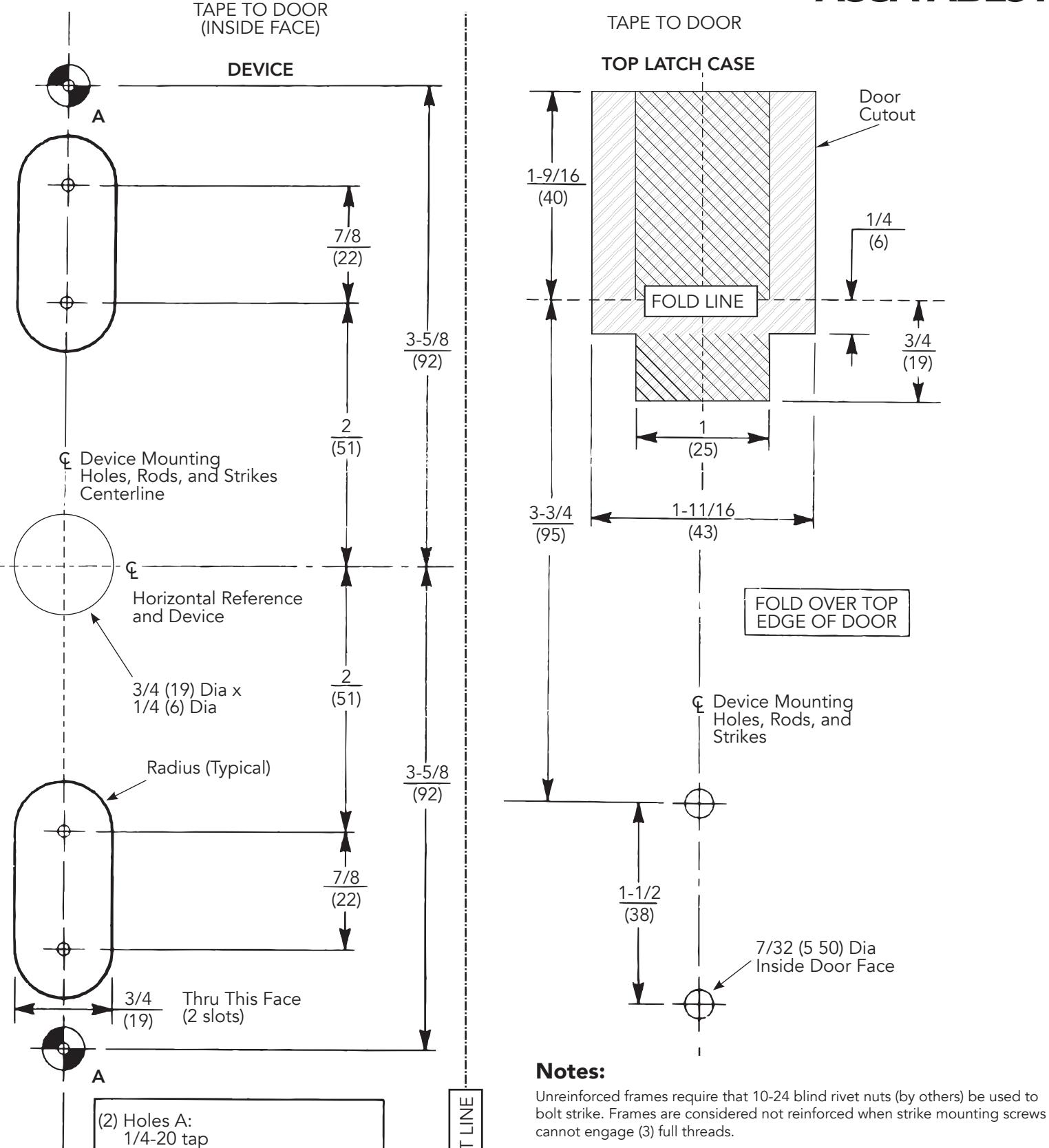
Dimensions are given in inches (mm).
Caution: Office copiers and facsimile machines may change the size of a drawing and make the template inaccurate to use as a door marker. If this is not the original template packed with the device, use only the dimensions written on the template to locate the holes on the door (do not use the template as a door marker).
80-9472-0020-000 10/23
(all other doors)
(metal reinforced doors),
3/8 (9.5) dia thru door for SNB

This page left blank intentionally.
ASSA ABLOY TAPE TO FRAME RABBET TAPE TO DOOR POSITION ON FLOOR 791 STRIKE BOTTOM BOLT CASE 790 STRIKE (Floor Strike) (Top Strike) Align with & rods line and door face (device side) 7/32 (5 50) Dia Inside Door Face FOLD LINE 5/8 (16) Dia x Rods and Strike 3/4 (19 Deep) Device Mounting Holes, Rods, and Frame Face Strikes Rods and Strike (3) FOLD LINE REF. Rabbet (Over Door) (Door Bottom) Stop Face CUT LINE CUT LINE Striker Marker (Tape as shown) Fold under bottom edge of door Device Mounting Holes, Rods, and Strikes INSIDE DOOR FACE (Device Side) CUT LINE ROD SETUP GAUGE TOP OF DOOR BOTTOM OF DOOR € Device TOP OF DOOR BOTTOM OF DOOR Alignment Hole Alignment Hole Device Holes and Rods 2-1/8 2-3/4 (54)(70)

Installation Instructions
This page left blank intentionally.
ASSA ABLOY
Installation Instructions
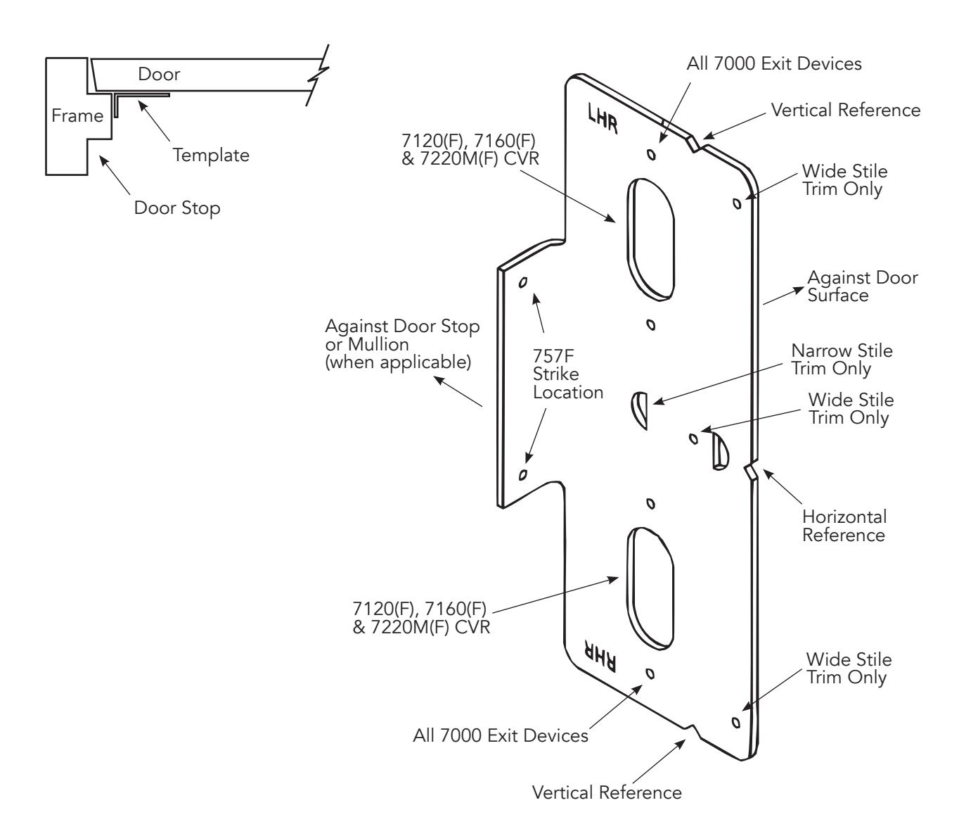
For use in conjunction with instruction sheets packed with exit device.
Holes and slots are identified below by exit device series and trim. Prep door and frame for only those features required for the exit device being installed.


This product can expose you to lead which is known to the state of California to cause cancer and birth defects or other reproductive harm. For more information go to www.P65warnings.ca.gov.