ASSA ABLOY ACCENTRA 7000 Series Motorized Electric Latch Retraction (MELR_80-9477-0782-000
Open the original PDF document
View PDF

7000 Series Exit Devices
Installation Instructions
With Optional S Bolt Monitor, B Touchbar Monitor, and O Trim Monitor Connection
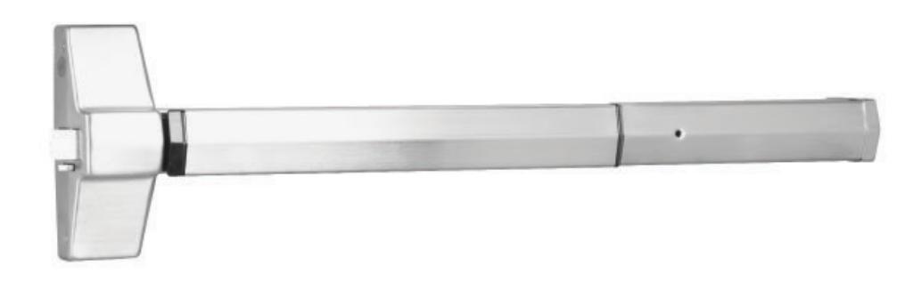
NOTE: These installation instructions cover standard product only. To install options, such as shim kits, refer to the instructions packed with the optional component.

WARNING
This product can expose you to lead which is known to the state of California to cause cancer and birth defects or other reproductive harm. For more information go to www.P65warnings.ca.gov.

WARNING
Attention Installer: Any retrofit or other field modification to a fire rated opening can potentially impact the fire rating of the opening, and ASSA ABLOY makes no representations or warranties concerning what such impact may be in any specific situation. When retrofitting any portion of an existing fire-rated opening, or specifying and installing a new fire-rated opening, please consult with a code specialist or local code official (Authority Having Jurisdiction) to ensure compliance with all applicable codes and ratings.
7000 Series Exit Devices Installation Instructions
Table of Contents
| 1. Overview | 3 |
|---|---|
| 1.1 Functions | 3 |
| 1.2 Installation Notes | 3 |
| 1.3 Hinge Requirements. | 4 |
| 1.4 Wire Gauge Chart. | 4 |
| 1.5 Power and Contact Ratings. | 4 |
| 1.6 Wire Cover Installation. | 5 |
| 1.7 Wire Locations and Positions. | 6 |
| 1.8 DIP (Dual Inline Package) Switch Settings. | 7 |
| 1.9 ElectroLynx Wiring System. | 8 |
| 2. Power Mode | 9 |
| 2.1 Power Mode Installation | 9 |
| 2.2 Power Mode Wiring. | 11 |
| 2.3 Configuration Instructions DIP Switch Settings. | 12 |
| 2.4 LED Signaling | 12 |
| 2.5 Power Mode Troubleshooting | 13 |
| 3. Timer Mode | 14 |
| 3.1 Timer Mode Installation | 14 |
| 3.2 Timer Mode Installation Wiring. | 15 |
| 3.3 Timer Mode Adjustment (Onboard Timer). | 17 |
| 3.4 Configuration Instructions DIP Switch Settings. | 17 |
| 3.5 LED Signaling Chart | 18 |
| 3.6 Timer Mode Troubleshooting | 18 |
| 4. Optional O Trim Monitor Switch | 19 |
7000 Series Exit Devices
Installation Instructions
1. Overview
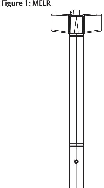
The Commercial Motorized Latch Retraction (MELR), see Figure 1, works with the Commercial 7000 Series Exit Devices (7100, 7150, 7110, 7170, 7120, 7160, 7200, 7250, 7210, and 7220) to provide remote-controlled latch retraction option. It is compatible with the following:
- S Latchbolt Position Monitor: Provides indication of the position of the latch bolt. Used with security systems to monitor the latch bolt. Also used to activate automatic door operators upon latch retraction.
- B Touchbar Monitor: Provides indication of the pushbar being depressed. Used as a request to exit to shunt alarm systems, release electromagnetic locks or monitor egress.
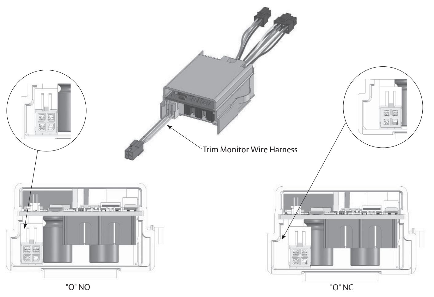
- O Trim Monitor Switch Provides indication of the device being operated from the outside. Used as a request to enter signal switch to shunt alarms. Also used to monitor entry.
NOTE: The MELR option is also compatible with hex key, cylinder key and fire rated mechanical configurations.
1.1 Functions
The MELR option can be configured to work in either of two modes:
- "2. Power Mode" on page 9: The device is not energized when locked. When power is applied, the pushbar and latch(es) will retract and remain in the retracted position until power is removed. Power is typically applied through a relay triggered by an access control device.
-
"3. Timer Mode" on page 14: The device is always energized and retraction is triggered by a momentary or maintain switch.
- When the timer circuit is closed using a momentary switch, the device retracts, remains retracted for a set duration, and releases. The duration of the retraction is set through an onboard timer setting.
- When the timer circuit is closed using a maintain switch, the device retracts. The device releases when the contact is opened.

Caution: Disconnect all input power before servicing.
- Installer must be a trained and experienced service person.
- Wiring must comply with applicable local electrical codes, ordinances and regulations.
- Hex key or cylinder (7XX5) mechanical dogging CANNOT be used on Fire Rated Doors.
1.2 Installation Notes
- The MELR option pushbar works only with Commercial 7000 Series exit devices.
- Always perform mechanical installation using the appropriate installation instructions, prior to electrical wiring.
- Earth Ground: Required for electrostatic discharge (ESD) protection, unless grounded through the metal door and frame.
7000 Series Exit Devices Installation Instructions
1.3 Hinge Requirements
| Hinge Information | |||||
|---|---|---|---|---|---|
| Without Timer | With Timer | ||||
| Application | Wires | Recommended Hinge | Wires | Recommended Hinge | |
| MELR | 3 | QC8 | 5 | QC12 | |
| S MELR | 5 | QC8 | 7 | QC12 | |
| B MELR | 6 | QC8 | 8 | QC12 | |
| S, B MELR | 8 | QC8 | 10 | QC12 | |
| O MELR | 5 | QC12 | 7 | QC12 | |
| S, O MELR | 7 | QC12 | 9 | QC12 | |
| B, O MELR | 8 | QC12 | 10 | QC12 | |
| S, B, O MELR | 10 | QC12 | 12 | QC12 | |
1.4 Wire Gauge Chart
| Wire Gauge Information | ||||||||
|---|---|---|---|---|---|---|---|---|
| Total One-Way Length | Load Current @ 24VDC | |||||||
| of Wire Run (ft.) | 1/4A | 1/2A | 3/4A | *1A | 1-1/4A | 1-1/2A | 2A | 3A |
| 100 | 24 | 20 | 18 | 18 | 16 | 16 | 14 | 12 |
| 150 | 22 | 18 | 16 | 16 | 14 | 14 | 12 | 10 |
| 200 | 20 | 18 | 16 | 14 | 14 | 12 | 12 | 10 |
| 250 | 18 | 16 | 14 | 14 | 12 | 12 | 12 | 10 |
| 300 | 18 | 16 | 14 | 12 | 12 | 12 | 10 | - |
| 400 | 18 | 14 | 12 | 12 | 10 | 10 | - | - |
| 500 | 16 | 14 | 12 | 10 | 10 | - | - | - |
| 750 | 14 | 12 | 10 | 10 | - | - | - | - |
| 1,000 | 14 | 10 | 10 | - | - | - | - | - |
| 1,500 | 12 | 10 | - | - | - | - | - | - |
| *When calculating voltage drop, use 1A as the recommended current draw for the MELR | ||||||||
1.5 Power and Contact Ratings
MELR Contact Ratings
Voltage: 24VDC
• Filtered and regulated power supply
• Motor operating current: 600mA
• Motor hold current: 250mA
| Contact Ratings | ||||
|---|---|---|---|---|
| S Latch Bolt | B Touch Bar | O Trim | ||
|
200mA@28VDC
1A@30VDC 1A@28VDC |
||||
7000 Series Exit Devices
Installation Instructions
1.6 Wire Cover Installation
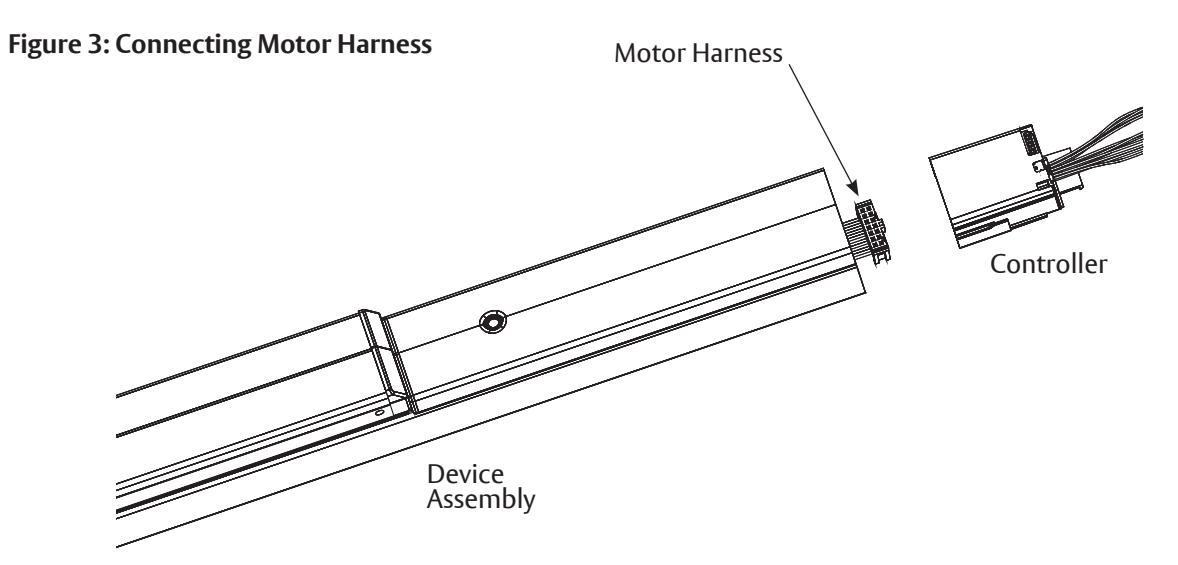
1. While holding motor harness, slide wire cover all the way into the device assembly.
Figure 2: Installing Wire Cover
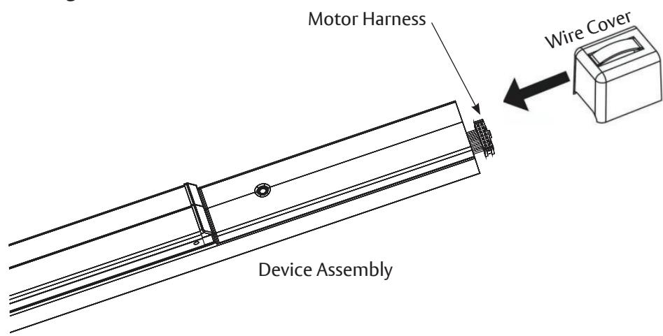
2. Plug motor harness into controller.
7000 Series Exit Devices Installation Instructions
1.6 Wire Cover Installation, continued
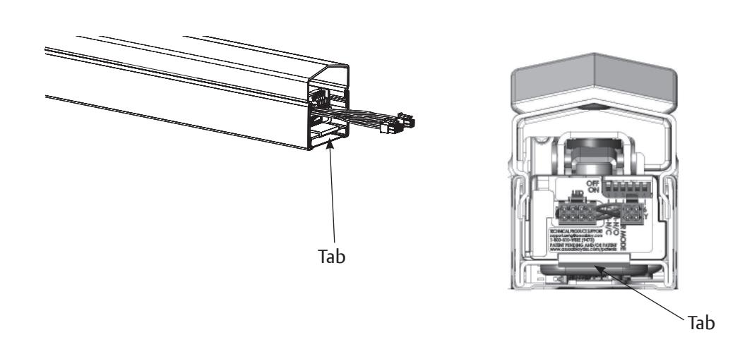
3. Slide controller into touch bar, making sure tab is securely attached over end of chassis.
Figure 4: Tab Attachment
1.7 Wire Locations and Positions
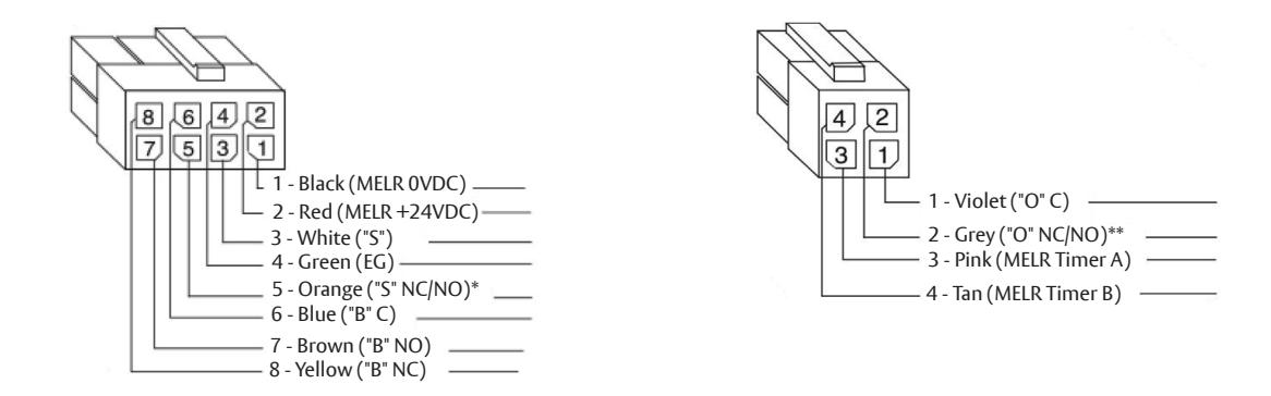
MELR option devices are supplied with one (1) 4-pin and one (1) 8-pin Molex® connector (See Figure 5). Molex connectors allow simple installation using the ASSA ABLOY ElectroLynx® system.
Figure 5: Wire Color and Position
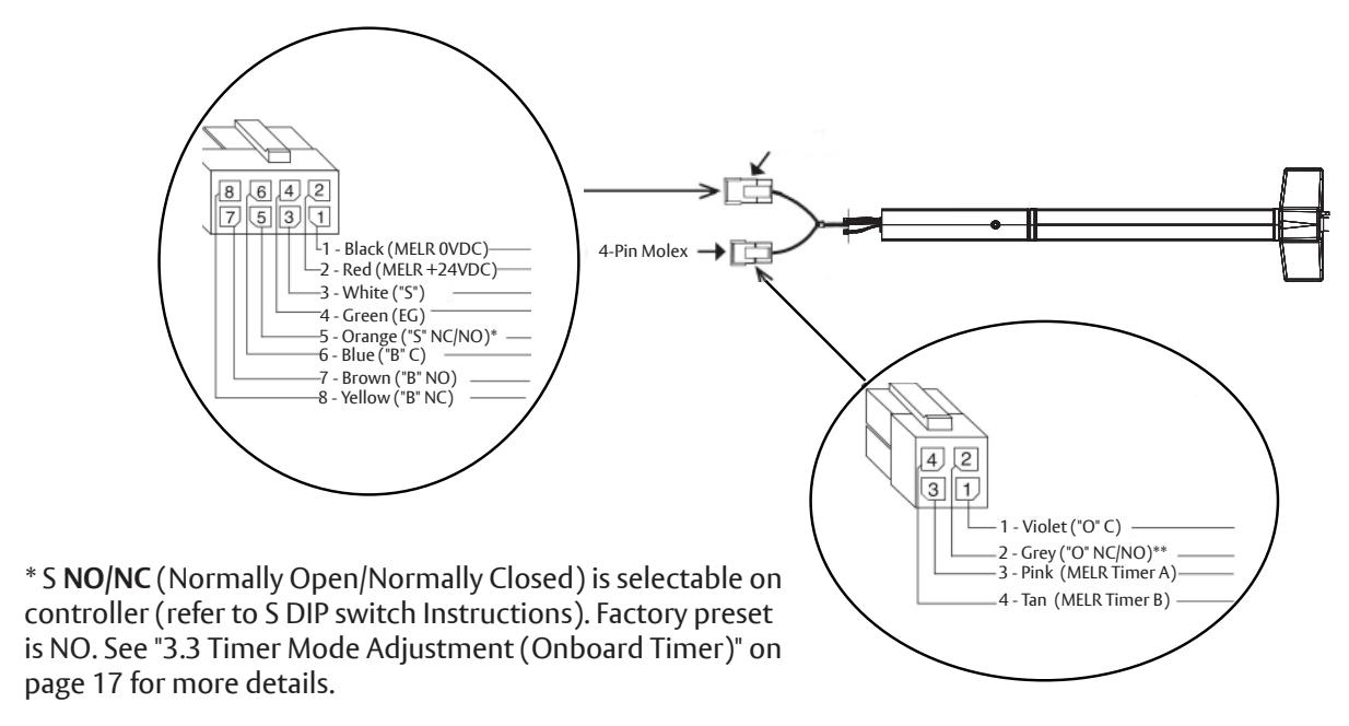
** O NO/NC (Normally Open/Normally Closed) is selectable on controller. Factory preset is NO. See "4. Optional O Trim Monitor Switch" on page 19 for details.
7000 Series Exit Devices
Installation Instructions
1.8 DIP (Dual Inline Package) Switch Settings
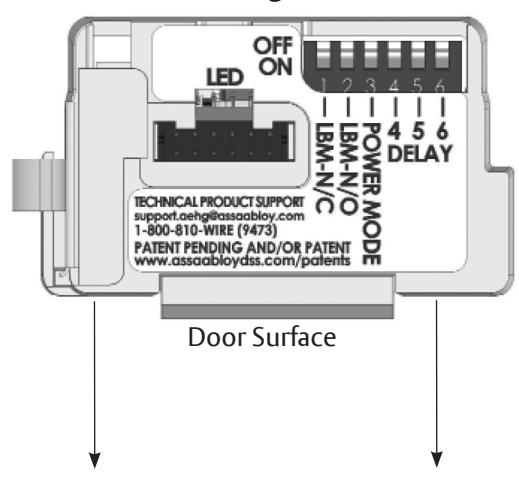
Figure 6: DIP Switch Settings (Factory Default Shown)
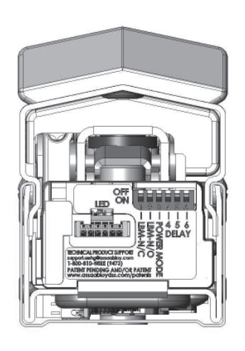
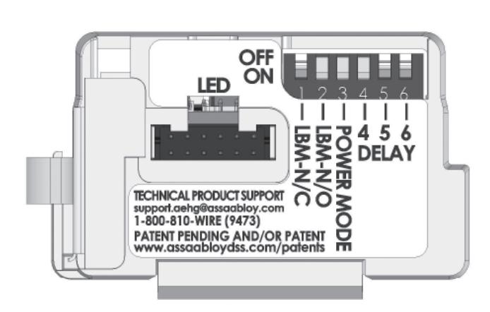
DIP Switch assignments are as follows, starting from left in Figure 6:
- a. Closed (Switch #1 set to ON ) when selecting LBM/NC (Normally Closed) contact, Or
- b. Closed (Switch #2 set to ON ) when selecting LBM/NO (Normally Open) contact.
NOTES:
- Only 1 or 2 should be closed at one time, not both.
- 3: Closed when bypassing external trigger, i.e. Power Mode.
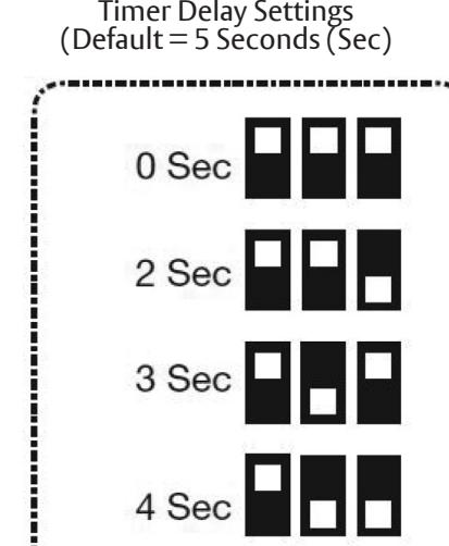
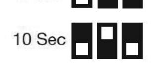
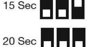
- 4, 5, 6: Select software options, allows up to 8 Time/Delay settings (See Section 3 Timer Mode).
- Default Setting: LBM/NO and Power Mode set to ON.
7000 Series Exit Devices Installation Instructions
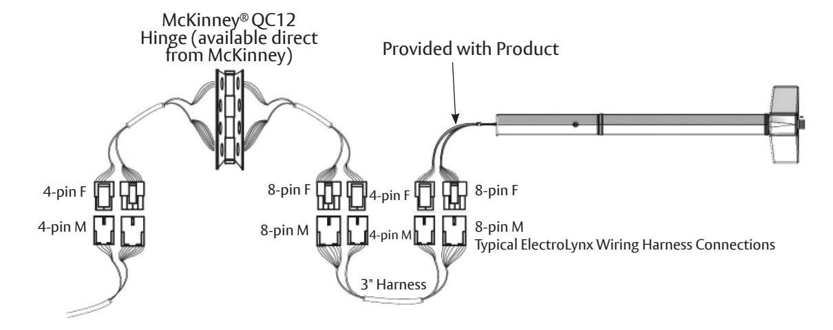
1.9 ElectroLynx Wiring System
IMPORTANT: Do Not Force - ElectroLynx connectors plug and lock together in only one way. See Figures 7 and 8.
Figure 7: ElectroLynx Connections
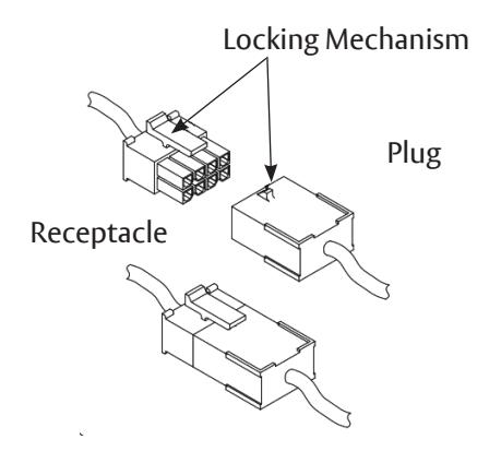
Figure 8: Typical ElectroLynx Wiring
NOTES:
- Devices ordered with S, B, O and MELR Options wired in Timer Mode require all 12 wires.
- The 3" Harness is not included with the product, door or hinge and must be ordered separately.
7000 Series Exit Devices
Installation Instructions
2. Power Mode
2.1 Power Mode Installation Instructions
In this configuration, the device is not energized when locked. When energized with a 24 volt input, the pushbar and latch(es) will retract and remain in the retracted position until power is removed. Power is typically applied through a relay triggered by an access control device. For installations using the onboard timer circuit, refer to "3. Timer Mode" on page 14.
Rail retracts when power is applied and releases when power is removed.
1. Mount 7000 Series exit device using mechanical installation instruction sheet(s) provided.
NOTES:
- Ensure proper mechanical function before attempting electrical retraction.
- Verify the pushbar can be fully depressed and the latch is fully retracted.
- On vertical rod devices, verify latch bolts do not enter hold-back position until pushbar is fully depressed.
- Adjust device mechanically as required, before applying power.
- 2. Connect the ElectroLynx harness in the door. See Figure 9.
Figure 9: Typical ElectroLynx Power Mode Wiring
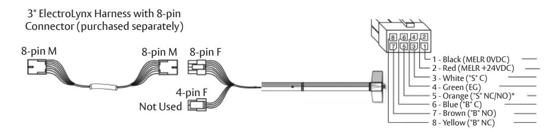
- * S NO/NC (Normally Open/Normally Closed) is selectable on controller (refer to S DIP switch instructions in "3. Timer Mode" on page 14). Factory preset is NO.
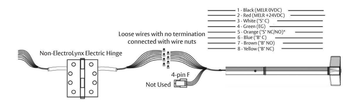
- 3. Plug the 8-pin ElectroLynx connector from the pushbar into the 3" ElectroLynx harness or splice into non-ElectroLynx harness. See Figure 10.
Figure 10: Non-ElectroLynx Power Mode Wiring MELR Wires with ElectroLynx Connector Removed
7000 Series Exit Devices Installation Instructions
2.1 Power Mode Installation Instructions, continued
4. Feed the 3" harness through the 1" hole in the door and secure the pushbar to the door using the mounting bracket and two (2) supplied screws (Figure 11).
NOTES:
- Do not install the end cap until electrical operation is verified in order to confirm LED signaling.
- Do not discard the end cap and hardware.
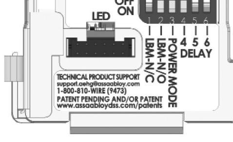
- 5. Ensure DIP switch (position 3) enables Power Mode (Figure 12).
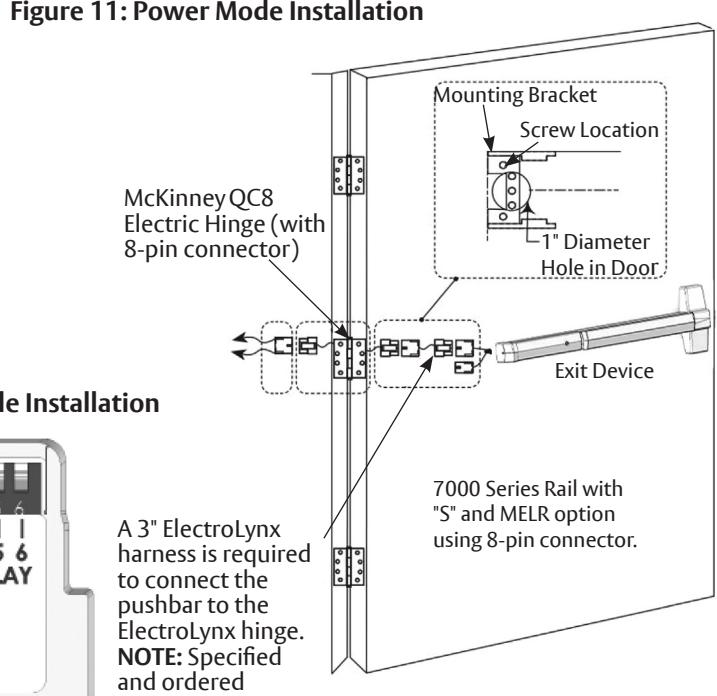
separately.
Figure 12: DIP Switch Setting for Power Mode Installation
6. Connect the ElectroLynx harness to the hinge and secure the hinge to the door.
NOTES:
- Make sure no wires are pinched or damaged in the process.
- Refer to detailed wiring instructions under "2.2 Power Mode Wiring" on page 11.
- 7. Apply a 24V source which complies with the Content Ratings table MELR contact ratings. Confirm the LED is blinking, the system fully unlocks and all bolts clear the strikes. Troubleshoot the device if issues are observed using the steps outlined at the end of this section.
- 8. Store excess wiring under end cap and assemble with provided screws. Avoid pinching wires.
NOTE: Earth Ground is required for Electrostatic Discharge (ESD) protection unless the metal door and frame are already earth grounded; otherwise, earth ground wiring is required at pin 4. See Figure 9.
7000 Series Exit Devices
Installation Instructions
2.2 Power Mode Wiring
ElectroLynx Opening Installation
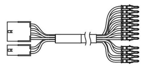
This is the simplest installation method, requiring the installer to plug the ElectroLynx connectors from the exit device to the harness to the hinge and then to the pigtail, which is connected to the access control system.
Requirements:
- MELR Exit Device
- 3" ElectroLynx connector harness (not supplied with MELR option)
- McKinney QC ElectroLynx hinge (type of hinge depends on the application)
- ElectroLynx door
Non-ElectroLynx Opening Installation
Standard door with standard electric hinge. Molex connectors with flying leads purchased separately (See Figure 13 and the Molex Connectors Table).
Figure 13: Molex with 12-Pin Connector Pinned
| Molex Connectors | |||
|---|---|---|---|
| Size | Both Ends | To PINS | |
| 3 Inch | QC-C003 | QC9C003P | |
| 6 Inch | QC-C006 | QC9C006P | |
| 12 Inch | QC-C012 | QC9C012P | |
To identify part numbers and order harness(es), visit the McKinney website, www.mckinneyhinge.com, and search the catalog for ElectroLynx.
If Molex pinned connectors are not available, remove the ElectroLynx connector from the MELR Exit Device and wire nut the MELR wires to the wires from the electric hinge (color coordinating wire colors is recommended).
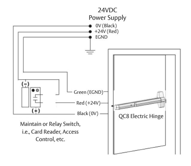
Power Mode Wiring
Use when wiring in Power Mode. See Figure 14.
NOTES:
- Onboard timer will not function in Power Mode. Add external time delay, if necessary.
- The switch is wired between the power supply and the load. Do not cycle the power supply.
Figure 14: MELR 7000 Series Exit Device Typical Power Mode Wiring
7000 Series Exit Devices Installation Instructions
2.3 Configuration Instructions DIP Switch Settings (S)
For MELR applications using the optional S latch bolt monitor switch, pin 5 of the 8-pin ElectroLynx connector will be either a NO contact or NC contact, depending on the position of the DIP switches on the motor controller faceplate (Figure 15).
Figure 15: Molex with 12-Pin Connector Pinned
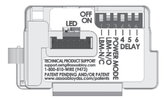
DIP Switch Setting for "S" Latch Bolt Monitoring NO (Default) Shown
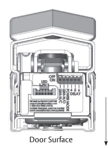
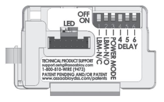
NC Alternative DIP Switch Setting
2.4 LED Signaling
| Signal | Cause | Troubleshooting |
|---|---|---|
| Dark / Unit | Controller micomprocessor is not active | Confirm connections and incoming power |
| Steady Flashing | Normal operation | Check that Power Mode switch is set |
| Solid Light |
Input voltage is dropping out of
operating range |
Check wire run and power supply output |
| Two Flashes Followed by Pause | Retractor sensor problem | Call 1-800-810-WIRE (9473) for assistance |
7000 Series Exit Devices
Installation Instructions
2.5 Power Mode Troubleshooting
Prior to electrical troubleshooting, confirm that the mechanical system properly functions; i.e., that the pushbar fully retracts all latches and the door opens freely. See the table below. Refer to applicable Commercial 7000 Series Exit Device product instruction sheet to correct mechanical installation issues.

IMPORTANT: *ALWAYS disconnect power before making any mechanical adjustments to the system.
Power Mode Troubleshooting
The pushbar does not move when 24V input is applied:
- Check inputs to confirm proper voltage and wiring orientation (Figure 6 ElectroLynx Power Mode Installation).
- Remove end cap from pushbar and confirm that LED is blinking steadily when power is applied. If not, refer to "2.4 LED Signaling" on page 12.
NOTE: When configured in Power Mode, power is released to lock the device (LED will not blink when power is released).
• Confirm DIP switch position 3 is set to ON.
The pushbar does not fully retract or pushbar retracts completely and holds but does not open door:
-
*Verify mechanical installation and correct as necessary:
- Is excessive force required to depress the pushbar?
- Are latches fully clearing the strikes when mechanically cycled?
The pushbar retracts and unlocks electrically but does not relock:
- Physically disconnect power from pushbar and confirm that input is off.
- *Check for mechanical interference (e.g., warped door, lack of shims, misalignment of pushbar, etc.).
Rail behaves abnormally (multiple cycles, clicking, delayed retraction, etc.):
• Remove end cap from pushbar and confirm that LED is blinking steadily when power is applied. If not, refer to LED signaling. NOTE: When configured in Power Mode, power is released to lock the device (LED will not blink when power is released).
For applications using automatic operator(s): Door(s) fail to unlock before doors begin to open:
• Adjust timing of operator to allow 900ms for the pushbar to fully retract.
S switch wiring: The design requires normally open functionality and the circuit is normally closed (or vice versa):
• There is only a two-wire input for the S circuit. Normally open or normally closed configuration is set by toggling the DIP switches on the controller bracket to the required position.
For additional installation assistance, please contact 1-800-810-WIRE (9473). When calling, please provide the following information to improve our service (provide what you can):
- Your name and contact number.
- Commercial 7000 Series Exit Device product type with options.
- Location and identification of the affected opening (e.g, site, building, and door number).
- Order number (located on product box), if available.
- Power supply manufacturer and rated output (i.e., voltage and current).
- Method of operation (e.g., Power Mode).
- The number of devices connected to the power supply.
- Symptoms of problem (i.e. observed behavior).
7000 Series Exit Devices Installation Instructions
3. Timer Mode
3.1 Timer Mode Installation Instructions
In this configuration, the device is always energized with a 24 volt input, and a timer circuit is opened or closed to control pushbar retraction. A momentary or maintain switch is typically used to perform this operation. For installations where the power input is cycled to retract the device, refer to "2. Power Mode" on page 9.
1. Rail retracts when timer input is closed. Mount 7000 Series exit device using mechanical installation instruction sheet(s) provided.
NOTE: Ensure proper mechanical function before attempting electrical retraction:
- Verify the pushbar can be fully depressed and the latch is fully retracted.
- On vertical rod exit devices, verify that the latch bolts do not enter hold-back position until the pushbar is fully depressed.
- Adjust device mechanically, as required, before applying power.
- 2. Ensure DIP Switch (position 3) disables Power Mode (Figure 16). Set to OFF to disable.
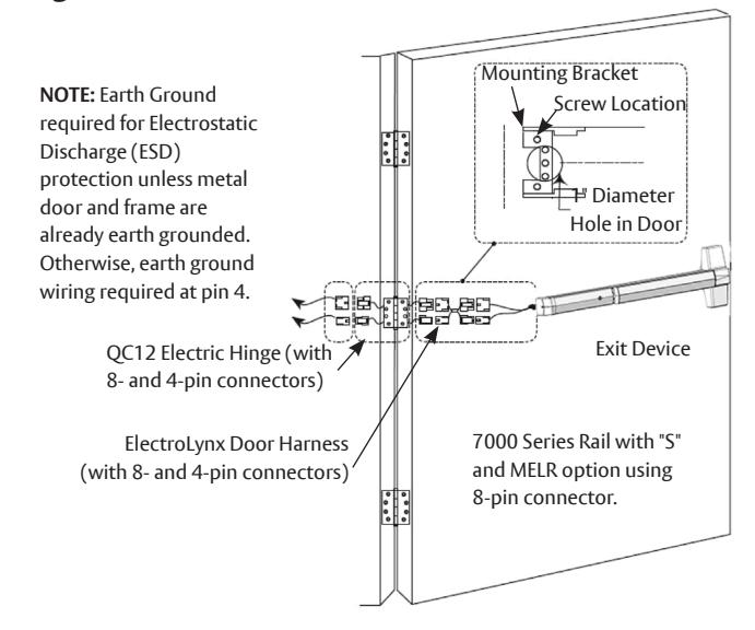
- 3. Connect the ElectroLynx harness in the door (Figure 17).
- 4. Plug the 8-pin and 4-pin ElectroLynx connectors from the pushbar into the 3" ElectroLynx harness or splice into a non-ElectroLynx harness.
- 5. Feed the 3" harness through the 1" hole in the door and secure the pushbar to the door using the mounting bracket and two (2) supplied screws.
NOTE: Do not install the end cap until electrical operation is verified in order to confirm LED signaling. Do not discard the end cap and hardware.
Figure 16: DIP Switch Setting for Timer Mode Installation Figure 17: Timer Mode Installation
- 6. Connect the ElectroLynx harness to the hinge.
- 7. Plug the door harness's 8-pin and 4-pin connectors into the hinge's ElectroLynx connector.
- 8. Secure the electric hinge to door.
NOTE: Ensure no wires are pinched or damaged in the process. Refer to detailed wiring instructions under "3.2 Timer Mode Installation Wiring" on page 15.
- 9. Apply 24V according to MELR contact ratings: Confirm that the LED is blinking and close the timer input circuit to retract the device. When the system retracts electrically, confirm that it fully unlocks and that all bolts clear the strikes. Troubleshoot the device if issues are observed using the steps outlined at the end of this section.
- 10. Store excess wiring under end cap and assemble with provided screws. Avoid pinching wires.
7000 Series Exit Devices
Installation Instructions
3.2 Timer Mode Installation Wiring
ElectroLynx Opening Installation
This is the simplest installation method, requiring the installer to plug the ElectroLynx connectors from the exit device to the harness to the hinge and then to the pigtail, which is connected to the access control system. See Figure 18.
Requirements:
- MELR Exit Device
- 3" ElectroLynx connector harness (not supplied with MELR option)
- McKinney QC ElectroLynx hinge (type of hinge depends on the application)
- ElectroLynx door
* S NO/NC (Normally Open/Normally Closed) is selectable on controller (refer to "3.4 Configuration Instructions DIP Switch Settings (for S & Timer Durations)" on page 17). Factory preset is NO.
Figure 18: Timer Mode Installation
3" ElectroLynx harness with 8- and 4-pin connectors (purchased separately).

** O NO/NC (Normally Open/Normally Closed) is selectable on controller. Factory preset is NO. See "4. Optional O Trim Monitor Switch" on page 19 for details if NC is preferred.
7000 Series Exit Devices Installation Instructions
3.2 Timer Mode Wiring, continued
Non-ElectroLynx Opening Installation
Standard door with standard electric hinge: Remove the Electrolynx connector from the MELR Exit Device and wire nut the MELR wires to the wires from the electric hinge. Color coordinating the wires are recommended.
| Molex Connectors | |||
|---|---|---|---|
| Size | Both Ends | To PINS | |
| 3 Inch | QC-C003 | QC9C003P | |
| 6 Inch | QC-C006 | QC9C006P | |
| 12 Inch | QC-C012 | QC9C012P | |
To identify part numbers and order harness(es), visit the McKinney website, www.mckinneyhinge.com, and search the catalog for ElectroLynx.
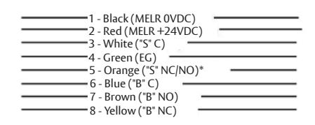
* S NO/NC (Normally Open/Normally Closed) is selectable on controller (refer to "3.4 Configuration Instructions DIP Switch Settings (for S & Timer Durations)" on page 17). Factory preset is NO.
Figure 19: Timer Mode Typical Wiring
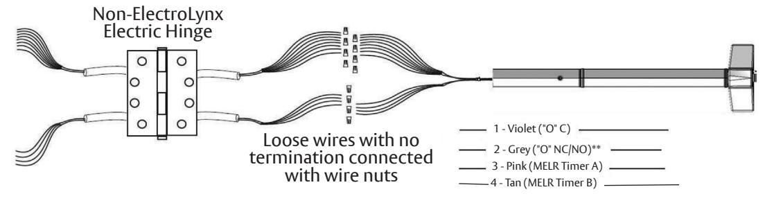
Timer Mode Typical Wiring
For use when wiring in Timer Mode (Figure 20) using the onboard timer. If more than 20 seconds timed delay is necessary, an external timer delay relay is required (not provided).
NOTE: 4V supply is constant in Timer Mode. Refer to settings in "3.4 Configuration Instructions DIP Switch Settings (for S & Timer Durations)" on page 17.
Figure 20: Non-ElectroLynx Timer Mode Connection MELR Wires with ElectroLynx Connector Removed
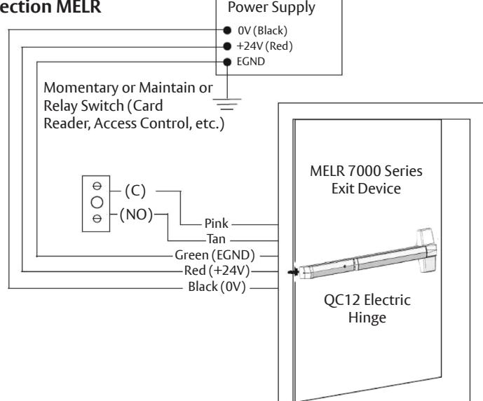
24VDC
7000 Series Exit Devices
Installation Instructions
3.3 Timer Mode Adjustment (Onboard Timer)
The 24 volt input is always energized and the system retracts when the timer input circuit is closed.
- When the timer circuit is closed utilizing a momentary switch, the device retracts, remains retracted for a set duration, and releases. The duration of retraction is set using an onboard timer setting (0 – 20 second timer adjustment).
- The device retracts when timer circuit is closed using a maintain switch and releases when circuit is reopened.
NOTE: 24V supply is constant in Timer Mode. The duration of retraction is determined by whichever is longer: the maintain switch closure or the onboard timer delay. If more than a 20 second delay is necessary (exceeding the maximum setting), an external timer delay relay is required (not provided). Refer to settings in Figure 21 for DIP Switch timer delay settings.
3.4 Configuration Instructions DIP Switch Settings (for S & Timer Durations)
For MELR applications using the optional S latch bolt monitor switch (S MELR), pin 5 of 8-pin ElectroLynx connector will be either NO or NC contact depending on position of the DIP switches on motor controller faceplate.
Figure 21: DIP Switch Settings
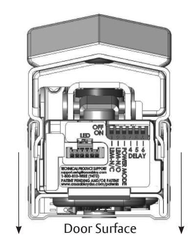
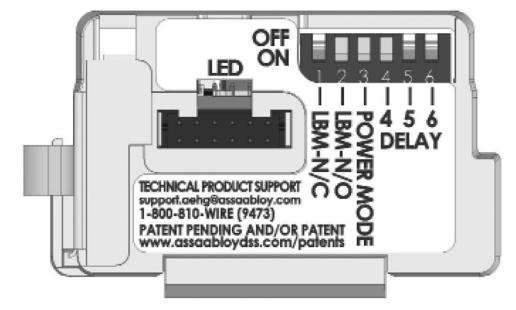
DIP Switch Setting for S Latch Bolt Monitoring NO (Default) Shown
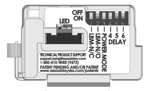
NC Alternative DIP Switch Setting
7000 Series Exit Devices Installation Instructions
3.5 LED Signaling Chart
| Signal | Cause | Troubleshooting |
|---|---|---|
| Dark / Unit | Controller micomprocessor is not active | Confirm connections and incoming power |
| Steady Flashing | Normal operation | Cycle device by closing the timer circuit |
| Solid Light |
Input voltage is dropping out of
operating range |
Check wire run and power supply output |
| Two Flashes Followed by Pause | Retractor sensor problem | Call 1-800-810-WIRE (9473) for assistance |
3.6 Timer Mode Troubleshooting
Prior to electrical troubleshooting, confirm that the mechanical system properly functions; i.e., that the pushbar fully retracts all latches and the door opens freely. Refer to applicable Commercial 7000 Series Exit Device product instruction sheet to correct mechanical installation issues.

IMPORTANT: *ALWAYS disconnect power before making any mechanical adjustments to the system.
The pushbar does not move when 24V input is applied:
- Check inputs to confirm proper voltage and wiring orientation. When configured for Timer Mode, 24V must be constantly applied and the timer circuit must be closed to cycle the device.
- Remove end cap from pushbar and confirm that LED is blinking steadily when power is applied. If not, refer to LED Signaling Chart.
The onboard timer duration adjustment is not working:
- Remove power when making adjustments to timer delay settings (DIP Switches).
- When a momentary signal is applied to timer circuit, circuit must be reopened for timer to function.
The pushbar does not fully retract or pushbar retracts completely and holds but does not open door:
-
*Verify mechanical installation and correct as necessary:
- Is excessive force required to depress the pushbar?
- Are latches fully clearing the strikes when mechanically cycled?
The pushbar retracts and unlocks electrically but does not release. System does not relock.
- Confirm that Timer Mode contact is opened (the pushbar will remain depressed until contact is opened and delay has expired).
- Physically disconnect power from pushbar (while electrically retracted) to verify if issue is mechanical.
- *Check for mechanical interference (e.g., warped door, lack of shims, misalignment of pushbar, etc.).
Rail behaves abnormally (multiple cycles, clicking, delayed retraction, etc.):
- If a momentary contact is applied to timer circuit, adjust onboard timer to a longer duration.
- Remove end cap from pushbar and confirm that LED is blinking steadily when power is applied. If not, refer to LED Signaling Chart.
For applications using automatic operator(s): Door(s) fail to unlock before doors begin to open:
- Adjust timing of operator to allow 900ms for the pushbar to fully retract.
- If a momentary contact is applied to the timer circuit, adjust the onboard timer to a longer duration to prevent the device from locking prior to operator actuation.
M91 switch wiring: The design requires normally open functionality and the circuit is normally closed (or vice versa):
• There is only a two-wire input for the S circuit. Normally open or normally closed configuration is set by toggling the DIP switches on the controller bracket to the required position (Figure 21).
7000 Series Exit Devices
Installation Instructions
3.6 Timer Mode Troubleshooting, continued
For additional installation assistance, please contact 1-800-810-WIRE (9473). When calling, please provide the following information to improve our service (provide what you can):
- Your name and contact number.
- Commercial 7000 Series Exit Device product type with options.
- Location and identification of the affected opening (e.g, site, building, and door number).
- Order number (located on product box), if available.
- Power supply manufacturer and rated output (i.e., voltage and current).
- Method of operation (e.g., Power Mode).
- The number of devices connected to the power supply.
- Symptoms of problem (i.e. observed behavior).
4. Optional O Trim Monitor Switch
For MELR applications using the optional O trim monitor switch, the NO or NC output can be selected on the controller. Factory preset is NO, however to change to NC perform the following:
- 1. Remove the controller for the exit device.
- 2. Move the trim monitor switch wire harness to the desired configuration as shown in Figure 22.
- 3. Place the controller back into the Exit Device, ensuring that the tab is attached to the Exit Device chassis.
NOTE: Connector position is relative to the block.
Figure 22: Changing O Preset