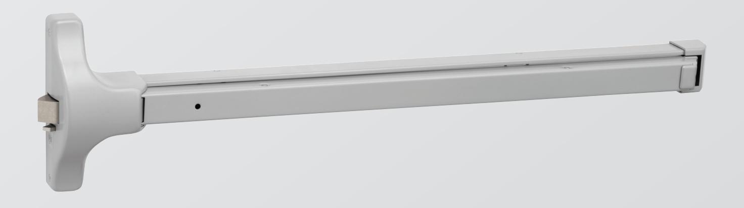
ASSA ABLOY ACCENTRA 7000 Series Architectural Exit Devices Parts Manual_42210
Open the original PDF document
View PDF

2100 Series
Economy Exit Devices Parts Manual

This product can expose you to lead which is known to the state of California to cause cancer and birth defects or other reproductive harm. For more information go to www.P65warnings.ca.gov.
Table of Contents

| Finish Chart | |
|---|---|
| Installation Notes | |
| How to Order Parts | |
| Handing | |
| Exit Devices | |
| 2100/2100F Rim Exit Device | |
| 2100 Bar Assembly | |
| 2110/2110F Surface Vertical Rod Exit Device | 6-7 |
| Trim | |
| 213F, 214F, 217F Trim | 8 |
| Levers and Knobs | g |
| Lever/Rose Assemblies | |
| Cylinders | |
| Strikes | |
| Accessories | |
| Mullion Parts | |
| Handing Instructions | |
| Troubleshooting |
Finish Chart
| ANSI Code | Finish Description |
|---|---|
| 612* | Satin bronze, clear coated |
| 613* | Dark oxidized satin bronze, oil rubbed |
| 626* | Satin chrome plated |
| 630 | Satin stainless steel |
| 689 | Aluminum painted |
| 691 | Light bronze painted |
| 695 | Dark bronze painted |
* Trim finish option only.
Introduction

Installation Notes
- 1. Only fire-rated components can be used on fire-rated exit devices. Doing otherwise will void any type of product warranty, labeling and listing. Any component bearing the UL mark for fire rating cannot be supplied separately and maintain its rating without re-certification. Reference items with symbol.
- 2. Refer to the templates and installation instructions for complete door preparation and installation requirements.
- 3. Machine screws are provided for steel reinforced doors, threaded-to-the-head AB Type screws are provided for wood door applications. In addition, sex nuts and bolts are provided for fire-rated devices and are optional for non-rated devices. It is recommended that sex nuts and bolts be used for all exit device applications. This will improve the performance and extend the life of the product.
How to Order Parts
- 1. In order to simplify the ordering procedure and maintain regulatory compliance, parts are only available as listed.
- 2. To order parts, provide the appropriate quantity, part number, finish, hand (when required) and description as directed and illustrated below.
For example, use the following configuration to order:
- A) ten mullion stabilizer kits (page 19) to match 600 application (primed for painting)
- B) one surface vertical rod latch cover (page 6) in bright brass
| Quantity | Part Number | Finish | Hand | Description | |
|---|---|---|---|---|---|
| А | 10 | 81-9500-1417-FIN | 600 | Stabilizer Kit | |
| В | 1 | 60-7010-X040-FIN | 605 | Top Latch Cover |
For assistance, contact your authorized ACCENTRA" distributor or sales agency, or visit our website at www.accentra-assaabloy.com.
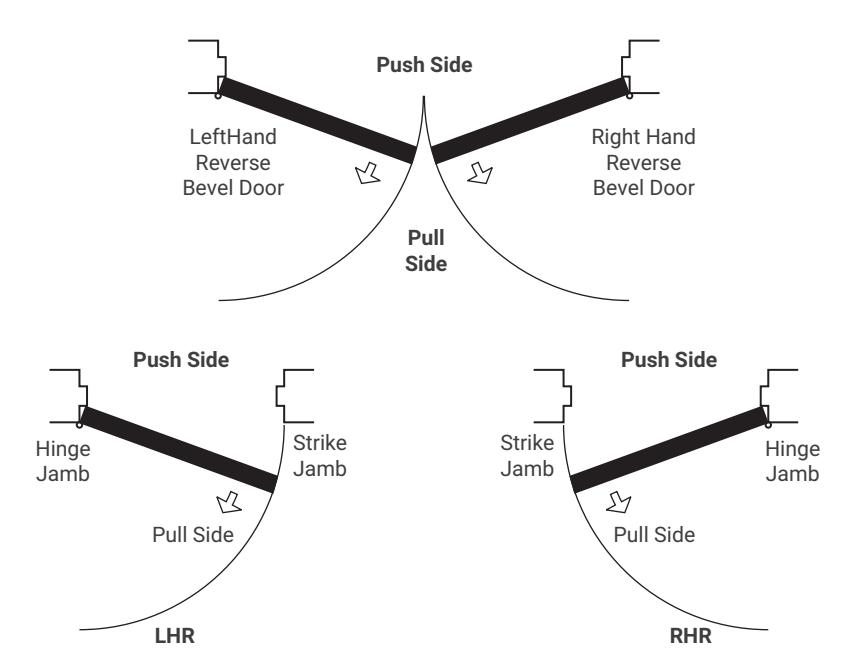
Handing
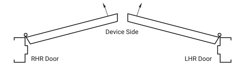
Left Hand Reverse: Hinges on left, opens outward. For handed devices, specify LHR.
Right Hand Reverse: Hinges on right, opens outward. For handed devices, specify RHR.
Note: Doors with Panic-Exit and Fire Exit hardware must open out. Therefore, hands must be reverse bevel.
ACCENTRA ASSA ABLOY
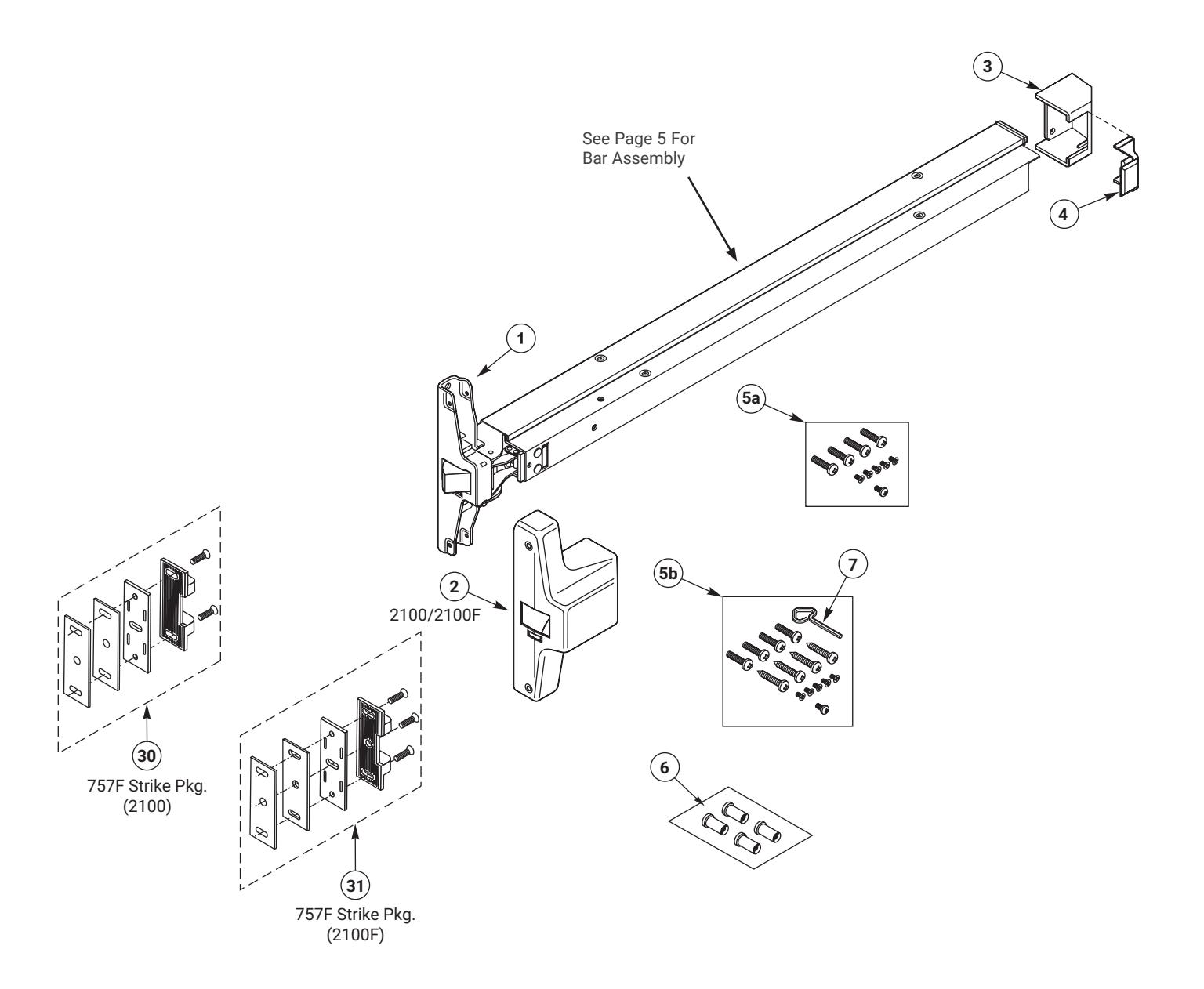
| ITEM | PART NO. | DESCRIPTION |
|---|---|---|
| 1 |
60-2100-0010-048
60-2100-0011-048 |
Latch Assembly
2100 2100F |
| 2 | 60-2100-6003-FIN |
Cover
2100 |
| 3 | 60-2000-6179-FIN | Bottom End Cap |
| 4 | 60-2000-6178-FIN | Top End Cap |
| ITEM | PART NO. | DESCRIPTION |
|---|---|---|
| 5a | 81-9500-1376-059 | Mtg. Screw Pack (2100F) |
| 5b | 81-9500-1395-059 | Mtg. Screw Pack (2100) |
| 6 | 03-0080-5047-FIN |
Sex Nut Pack (4) (2 Packs)
Fire Rated Only |
| 7 | 60-7000-1131-036 | Dogging Key |
| 30 | 81-9500-1356-200 | 757 Strike Packet (2100) |
| 31 | 81-9500-1373-200 | 757F Strike Packet (2100F) |

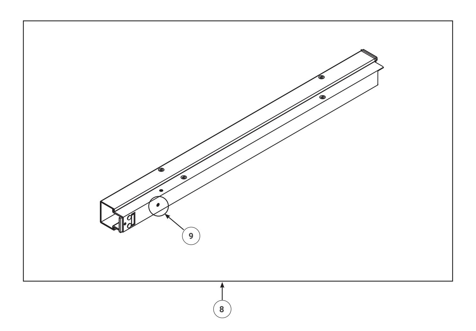
| ITEM | PART NO. | DESCRIPTION |
|---|---|---|
| 8 | 60-2100-0014-FIN | Dogging Bar Assembly, 36" |
| 8 | 60-2100-0015-FIN | Dogging Bar Assembly, 42" |
| 8 | 60-2100-0088-FIN | Dogging Bar Assembly, 48" |
| 8 | 60-2100-0008-FIN | Fire Rated Bar Assembly, 36" |
| 8 | 60-2100-0009-FIN | Fire Rated Bar Assembly, 42" |
| 8 | 60-2100-0087-FIN | Fire Rated Bar Assembly, 48" |
| ITEM | PART NO. | DESCRIPTION |
|---|---|---|
| 81-9500-1399-048 | Dogging Kit (Consists of the following) | |
| 60-2100-1001-999 | Dogging Drive | |
| 99-9999-7330-036 | Wavy Washer | |
| 9 | 60-2100-1007-048 | Bushing |
| 81-3815-0412-036 |
Screw, Thread Forming
Swage-Form/Trilobular or Equivalent Phillips Truss Head Machine 8-32 x 1/2" |
2110/2110F Surface Vertical Rod

| ITEM | PART NO. | DESCRIPTION |
|---|---|---|
| 1 | 60-2110-0002-048 |
Latch Assembly
2110, 2110F (Must Specify Hand) |
| 2 | 60-2110-6004-FIN |
Cover
2110 |
| 3 | 60-2000-6179-FIN | Bottom End Cap |
| 4 | 60-2000-6178-FIN | Top End Cap |
| 5a | 81-9500-1376-059 | Mtg. Screw Pack (2110F) |
| 5b | 81-9500-1395-059 | Mtg. Screw Pack (2110) |
| 6 | 03-0080-5047-FIN |
Sex Nut Pack (4) (2 packs)
Fire Rated Only |
| 7 | 60-7000-1131-036 | Dogging Key |
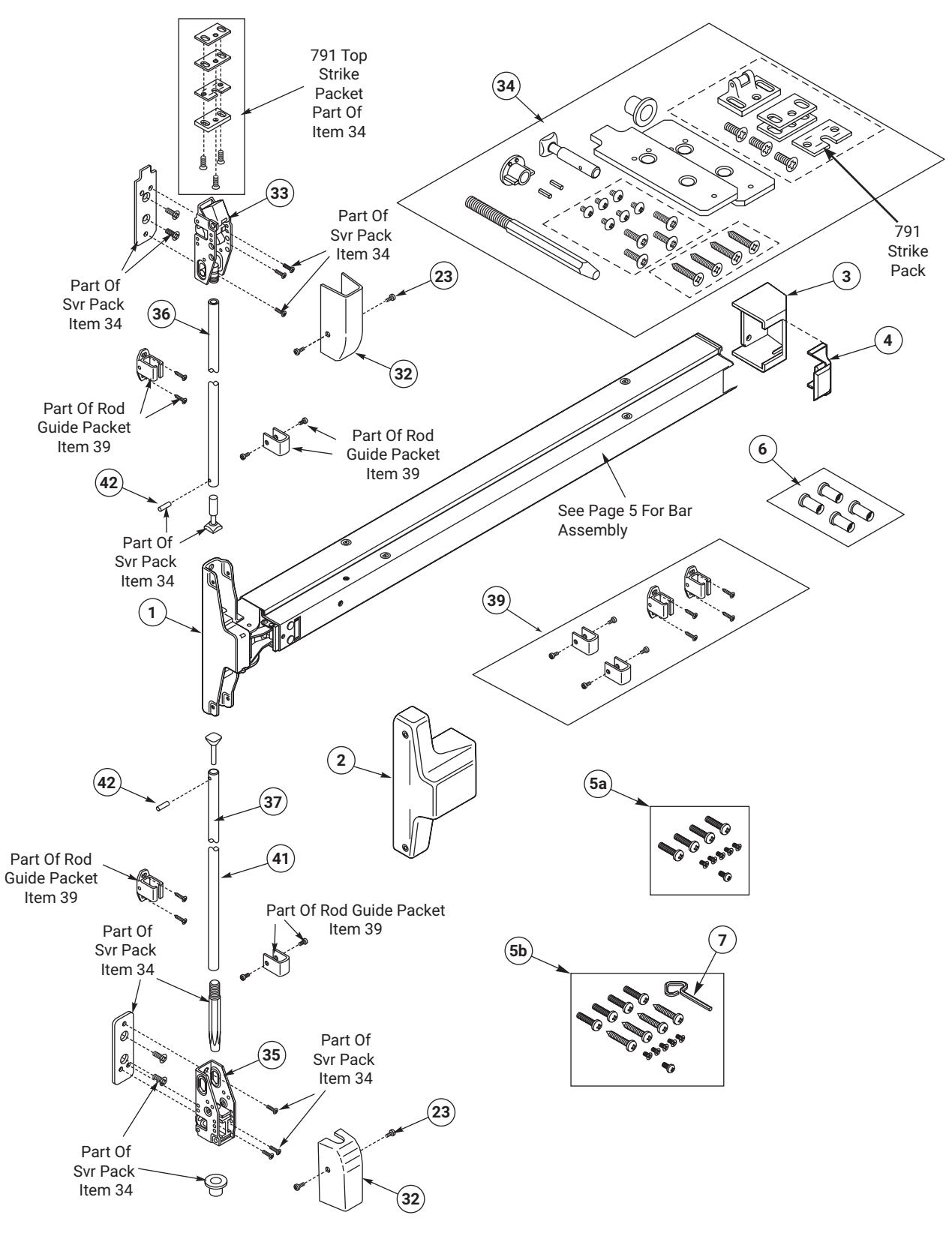
| 23 | 81-9500-1549-FIN |
Screw Packet, Cover
#8-32 x 5/16" UFPHMS (4) |
| 32 | 60-2010-X040-FIN |
Cover, Top & Bottom
Latch |
| 33 |
60-7010-0049-999
60-7010-0050-999 |
Top Latch
2110 2110F |
| ITEM | PART NO. | DESCRIPTION |
|---|---|---|
|
81-9500-1512-000
60-7010-1038-048 |
SVR Pack
Consists of the following: Top Mtg. Plate |
|
| 34 |
60-7010-1039-048
60-7010-1067-048 99-9999-4308-999 60-1500-6150-999 60-7010-1046-059 60-7010-1055-200 81-9500-1546-000 81-3111-0676-048 |
Bottom Mtg. Plate Top Rod Connector Spring Pin (2) Drill Jig Floor Bolt Strike Latch Mounting Screw Packet Latch Mounting Screw (4) (Wood Door Panic) |
| 81-9500-1454-200 | 791 Top Strike Packet | |
| 35 |
60-7010-0054-000
60-7010-0053-000 |
Bottom Bolt Case
2110 2110F |
| 36 | 60-2110-7006-FIN | Top Rod |
| 37 | 60-7010-1025-059 | Bottom Rod Connector |
| 39 | 81-9500-1514-FIN | Rod Guide Packet |
| 41 | 60-2110-7007-FIN | Bottom Rod |
| 42 | 99-9999-4308-999 | Spring Pin |

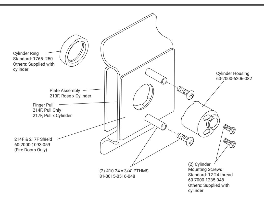
210 Series Trim
ACCENTRA ASSA ABLOY
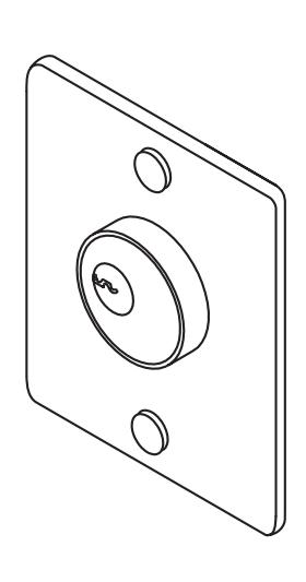
Nightlatch Access by Key 60-2100-0090-FIN
213F
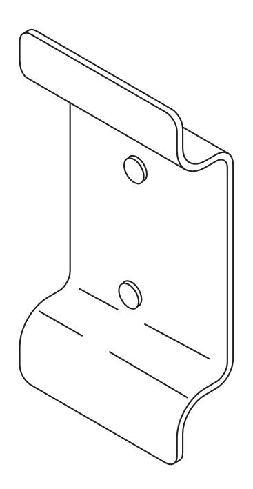
Dummy Trim Pull Plate 60-2100-0020-FIN
214F
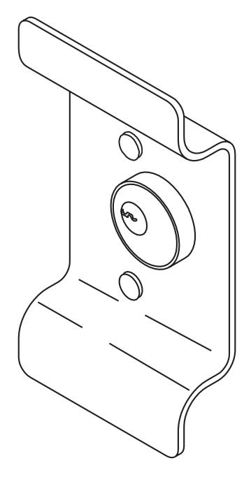
Night Latch Cylinder by Pull 60-2100-0021-FIN
217F
Levers & Knobs


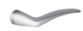
Arcadia
Projection: 3-1/16" (78mm) Lever assembly: RHR 60-7000-0097-FIN LHR 60-7000-0098-FIN
Augusta
ΑU
Projection: 2-5/16" (59mm) Lever assembly:
CR
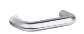
Carmel
Projection: 2-7/8" (73mm) Lever assembly: 60-7000-0140-FIN
JN
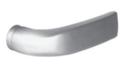
60-7000-0095-FIN
Jefferson Projection: 2-3/8" (60mm) Lever assembly: 60-7000-0093-FIN
МО
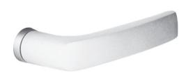
Monroe
Projection: 2-3/16" (71mm) Lever assembly: 60-7000-0239-FIN
РΒ
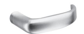
Pacific Beach
Projection: 2-3/4" (70mm) Lever assembly: 60-7000-0240-FIN
ΡN
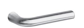
Pinehurst
Projection: 2-7/8" (73mm) Lever assembly: 60-7000-0198-FIN
VI
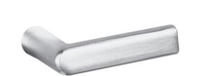
Virginia
Projection: 2-3/4" (70mm) Lever assembly: 60-7000-0236-FIN
Knob and Lever Handle Assemblies Include:
Spindle - P/N 60-7000-1243-059 Roll Pin - P/N 99-9999-3979-023
Outside Lever/Rose Assembly

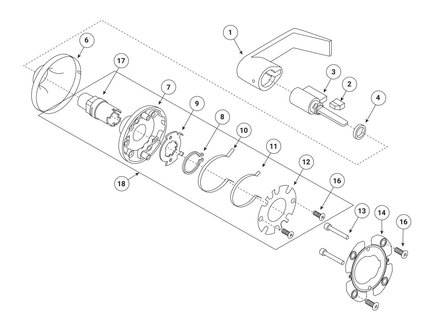
| ITEM | PART NO. | DESCRIPTION | QUANTITY |
|---|---|---|---|
| 1 | See Page 9 | Outside Lever Handle | 1 |
| 2 | 14-5407-9034-999 | Retainer Spring Pad | 1 |
| 3 | 1802-FIN-KEYWAY | Cylinder Assembly (Specify finish, see Page 2, and keyway) | 1 |
| 4 | 14-5407-9201-999 | Cylinder Spacer | 1 |
| 6 | 14-5401-2711-FIN | Rose Scalp (Specify finish, see Page 2) | 1 |
| 7 | 14-5401-6756-082 | Outside Rose Support | 1 |
| 8 | 14-5401-1619-000 | Snap Ring | 1 |
| 9 | 14-5401-1624-048 | Stop Plate | 1 |
| 10 | 14-5401-1641-999 | Lever Spring - Outside | 1 |
| 11 | 14-5401-1642-999 | Lever Spring - Inside | 1 |
| 12 | 14-5401-1757-048 | Cover | 1 |
| 13 | 14-5401-1410-048 | Pin | 2 |
| 14 | 14-5401-1623-048 | Outside Rose Plate | 1 |
| 16 | 81-3811-0406-048 | Screw #8-32 x 5/16" PHFH Trilobe | 4 |
| 17 | 14-5407-0100-048 | Removable Handle Shank/Retainer Assembly | 1 |
| 18 | 14-5407-0108-048 | Outside Rose/Shank Assembly | 1 |
Outside Lever/Rose Assembly

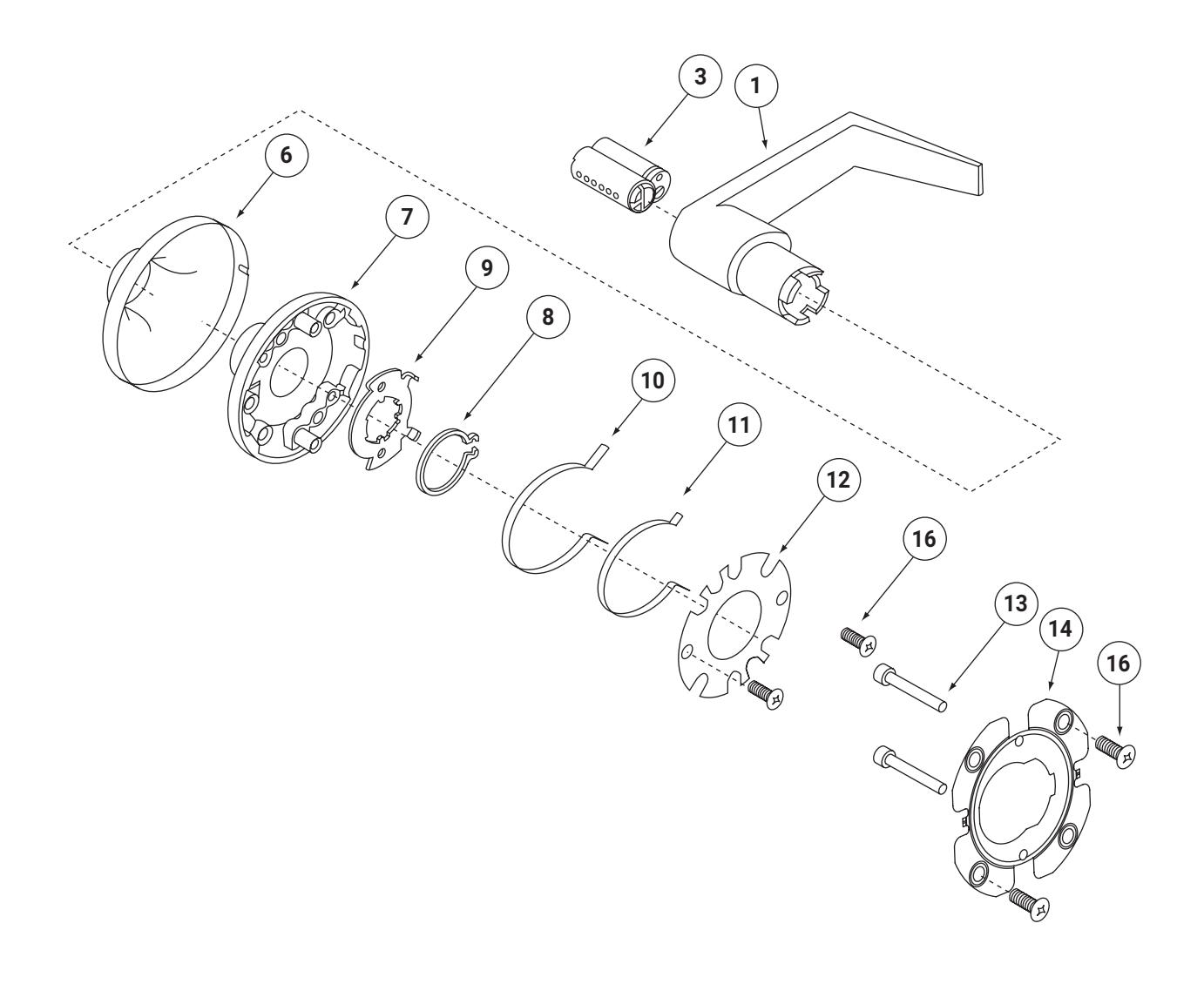
Outside Lever/Rose Assembly (Interchangeable Core)

| ITEM | PART NO. | DESCRIPTION | QUANTITY |
|---|---|---|---|
| 1 | See Page 9 | Outside Lever Handle | 1 |
| 3 | 1210-FIN-KEYWAY | Cylinder Assembly (Specify finish, see Page 2, and keyway) | 1 |
| 6 | 14-5401-2711-FIN | Rose Scalp (Specify finish, see Page 2) | 1 |
| 7 | 14-5401-6756-082 | Outside Rose Support | 1 |
| 8 | 14-5401-1619-000 | Snap Ring | 1 |
| 9 | 14-5401-1624-048 | Stop Plate | 1 |
| 10 | 14-5401-1641-999 | Lever Spring - Outside | 1 |
| 11 | 14-5401-1642-999 | Lever Spring - Inside | 1 |
| 12 | 14-5401-1757-048 | Cover | 1 |
| 13 | 14-5401-1410-048 | Pin | 2 |
| 14 | 14-5401-1623-048 | Outside Rose Plate | 1 |
| 16 | 81-3711-0406-048 | Screw #8-32 x 5/16" PHFH Trilobe | 4 |
Outside Lever/Rose Assembly (Interchangeable Core)

Interchangeable Core Lever Assemblies

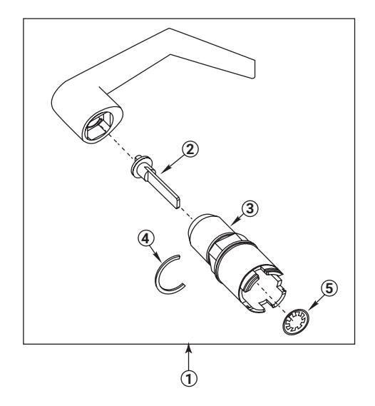
ACCENTRA 6-Pin
| ITEM | PART NO. | DESCRIPTION |
|---|---|---|
| 14-5407-0076-FIN* | AU Lever Assembly | |
| 1 | 14-5407-0019-FIN* | MO Lever Assembly |
| 14-5407-0030-FIN* | PB Lever Assembly | |
| 2 | _ | Cam and Connecting Bar Assembly |
| 3 | _ | Shank |
| 4 | _ | Retainer Shank |
| 5 | _ | Retaining Ring |
* Sold as an Assembly only.
ACCENTRA 7-Pin
| ITEM | PART NO. | DESCRIPTION |
|---|---|---|
| 14-5407-0077-FIN* | AU Lever Assembly | |
| 1 | 14-5407-0021-FIN* | MO Lever Assembly |
| 14-5407-0031-FIN* | PB Lever Assembly | |
| 2 | _ |
Cam and Connecting Bar
Assembly |
| 3 | _ | Shank |
| 4 | _ | Retainer Shank |
| 5 | _ | Retaining Ring |
* Sold as an Assembly only.
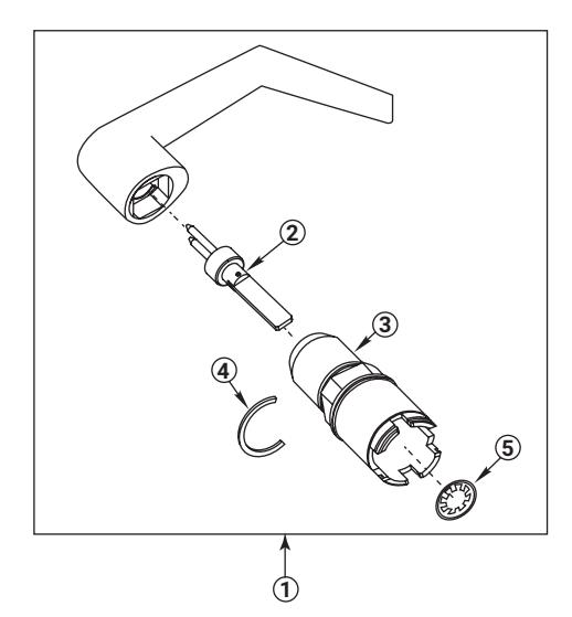
Corbin Russwin
| ITEM | PART NO. | DESCRIPTION |
|---|---|---|
| 1 | 14-5407-0141-FIN* | AU Lever Assembly |
| ı | 14-5407-0906-FIN* | PB Lever Assembly |
| 2 | _ |
Cam and Connecting Bar
Assembly |
| 3 | _ | Shank |
| 4 | _ | Retainer Shank |
| 5 | _ | Retaining Ring |
* Sold as an Assembly only.
Interchangeable Core Lever Assemblies

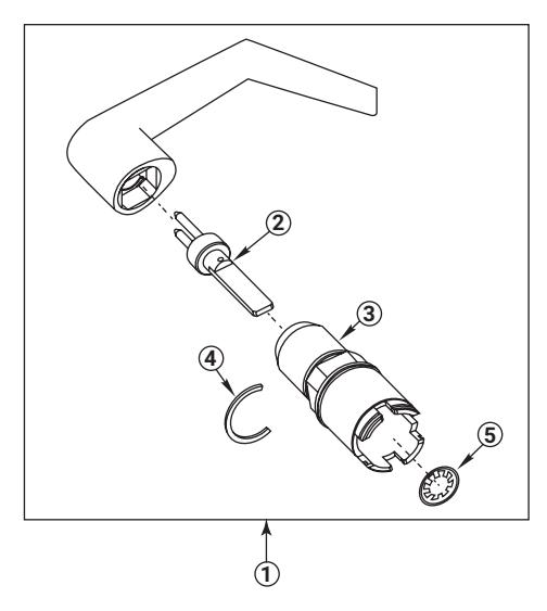
Best®
| ITEM | PART NO. | DESCRIPTION | ||
|---|---|---|---|---|
| 14-5407-0040-FIN* | AU Lever Assembly | |||
| 1 | 14-5407-0041-FIN* | MO Lever Assembly | ||
| 14-5407-0042-FIN* | PB Lever Assembly | |||
| 2 | _ | Cam and Connecting Bar Assembly | ||
| 3 | _ | Shank | ||
| 4 | _ | Retainer Shank | ||
| 5 | _ | Retaining Ring | ||
* Sold as an Assembly only.
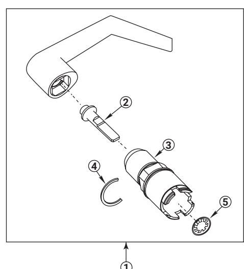
Schlage®
| ITEM | PART NO. | DESCRIPTION | ||
|---|---|---|---|---|
| 1 | 14-5407-0904-FIN* | AU Lever Assembly | ||
| l | 14-5407-0905-FIN* | PB Lever Assembly | ||
| 2 | _ | Connecting Bar | ||
| 3 | _ | Shank | ||
| 4 | _ | Retainer Shank | ||
| 5 | _ | Retaining Ring | ||
* Sold as an Assembly only.
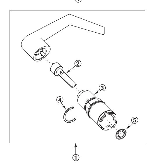
Medeco®, ASSA®
| ITEM | PART NO. | DESCRIPTION | ||
|---|---|---|---|---|
| 1 | 14-5407-0078-FIN* | AU Lever Assembly | ||
| 2 | _ | Connecting Bar | ||
| 3 | _ | Shank | ||
| 4 | _ | Retainer Shank | ||
| 5 | _ | Retaining Ring | ||
* Sold as an Assembly only.

| 2100/ | Application | Cylinder(s) | Description | Cylinder Collar |
Mounting
Screws |
||
|---|---|---|---|---|---|---|---|
| Rim Cylinder Standard Escutcheon Trim 520F/530F Series Rim Cylinders |
2100/2100F Rim
2110/2110F SVR |
1109 / 5109 6-pin | Standard / Security | 1765250 | 60-7000-1235-048 | ||
| U5109 6-pin | High Security | 60-7000-1235-048 | |||||
| | 3 | 1109 / 5109 7-pin | Standard / Security | 1765250 | 60-7000-1235-048 | |||
| Cylin | U5109 7-pin | High Security | 1766 | 60-7000-1235-048 | |||
| der | 1709 6-pin | CMK Cylinder | 1765656 | 34-2311-8738-048 | |||
| 1709 7-pin | CMK Cylinder | 1765656 | 34-2311-8738-048 | ||||
| 1193 / 5193 6-pin | Std. / Sec. I.C. | 1765469 | 10-1193-1018-048 | ||||
| 1193 / 5193 7-pin | Std. / Sec. I.C. | 1765656 | 10-1191-1018-048 |
Note: Mounting screw part numbers shown are the screws to mount the cylinder.
| Application | Cylinder(s) | Description | Cylinder Collar | |||
|---|---|---|---|---|---|---|
| Mortise | Keyed | 2100/2100F Rim | 2153/5153*, 6 or 7-pin, 1-1/8" (29mm) | Standard / Security | ||
| rtise Cylinder Cylinder | 2196 / 5196 6-pin | Std. I.C. / Sec. I.C. | 1765250 | |||
| inder | 2197 / 5197 7-pin | Std. I.C. / Sec. I.C. | 1765250 | |||
| Alarm Kit |
2100/2100F Rim
2110/2110F SVR |
2197, 7-pin 1-11/16" (42mm) | Std. I.C. 7-pin | 1765594 |
As with exit device trim you must order a cylinder to go with a keyed removable mullion. The ACCENTRA keyed removable mullion accepts a standard 6-pin 2153 mortise cylinder with cam #2160. Other cylinders are optional.
* U5153 6 and 7-pin cylinders cannot be used with a keyed removable mullion.
| Application | Cylinder(s) | Description | |
|---|---|---|---|
|
2100/2100F Rim
2110/2110F SVR |
1801 | 6-pin Knob Cyl. (Std.) | |
| 1802 | 6-pin Lever Cyl. (Std.) | ||
| 1802A | 7-pin Lever Cylinder | ||
| 1210 | 6-pin I.C. Lever Cylinder | ||
|
Knob or Leverset Trim
540F/580F Series Trim Keyed trim uses ACCENTRA cylindrical lock cylinders. |
1220 | 7-pin I.C. Lever Cylinder | |
| 5802 | 6-pin Security Lever Cyl. | ||
| 5802A | 7-pin Security Lever Cyl. | ||
| 5210 | 6-pin I.C. Security Cyl. | ||
| 5220 | 7-pin I.C. Security Cyl. | ||
| 107S | Adaptor kit for Schlage® Cyl. | ||
| "B" Trim Prefix | Trim with lever for Best®, Arrow® or Falcon® IC cylinder (specify 6 or 7-pin) | ||
| "R" Trim Prefix* | Trim with lever for Corbin Russwin IC cylinder |
* AU & PB levers only.
Strikes

Rim Devices
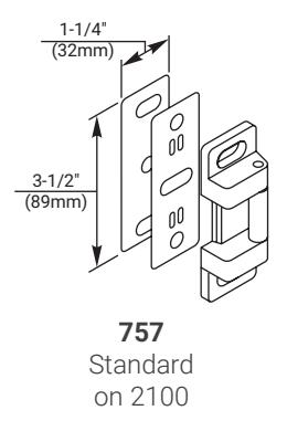
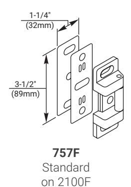
1-1/4" (32mm) (25mm) 0 0 0 0 0 0 0 0 0 0 0 0 0 0 0 0 0 0
793 Optional strike for double door applications without a mullion on 2100
Vertical Rod Devices
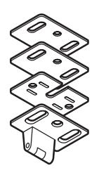
1-9/16" x 15/16" (40mm x 24mm)
791 Standard Top Strike on 2110, 2110F
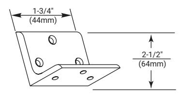
797 Bracket for SVR Top Strike in Flush Transom Opening on 2110F
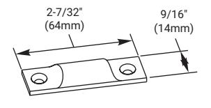
702 Floor Strike for optional bottom Pullman Latch
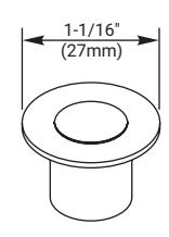
790 Standard Bottom Strike on 2110, 2110F
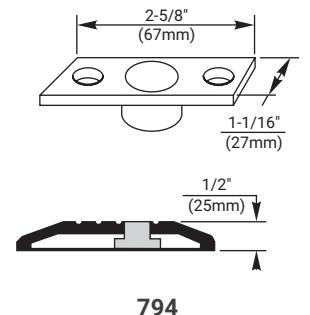
Optional Floor Strike for fire openings using saddle threshold, or flush floor mount. Must use for fire openings with thresholds.
Accessories

Shim Kits
224 For 2110/2110F Surface Vertical Rod Exit Device
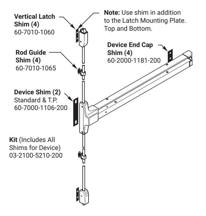
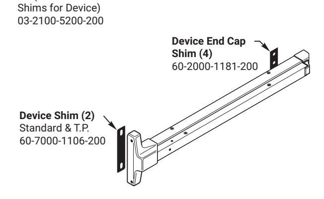
223 For 2110/2110F Rim Exit Device
Kit (Includes All
Surface Vertical Rod Extension Kits
Used to extend the height of standard length rods for 2100/2110F Series exit devices.
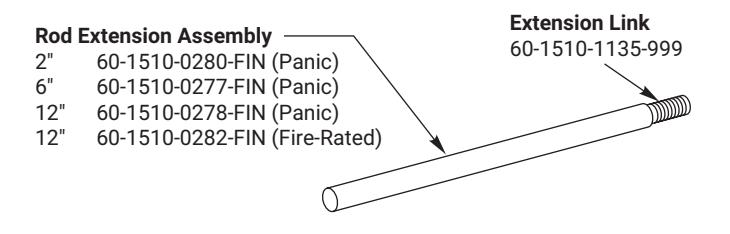
Optional Vertical Latches
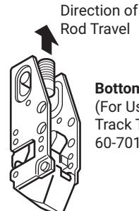
Bottom Pullman Latch (For Use With Latch
(For Use With Latch Track Thresholds) 60-7010-0051-999

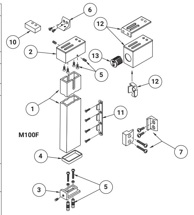
| ITEM | PART NO. | DESCRIPTION | ||||
|---|---|---|---|---|---|---|
| 1 |
60-1500-1267-114
60-1500-1265-114 60-1500-1266-114 |
Mullion
7' for M100(F) 8' for M100(F) 10' for M100(F) |
||||
| 2 60-1500-1283-078 | Bracket, Upper Mounting | |||||
| 3 | 60-2000-1164-078 |
Bracket, Lower Mounting
Panic/Fire Rated |
||||
| 4 | 60-2000-9158-999 | Anchor Pad (Fire Rated) | ||||
| 81-0011-0616-059 Scret 81-6219-2708-059 Set $ $ 5, $ 60-7000-1324-048 Scret 99-9999-7161-059 Lock | Screw Packet contains: | |||||
| 6 | 81-9500-0371-078 | Angle Bracket Packet contains: Angle Bracket (1) Screw #12-24 x 7/16" OHM-PH (2) | ||||
| 7 81-9500-1417-078 | Stabilizer Kit (optional) contains: Bracket, Stabilizer (2) Stabilizer (2) Spacer, Stabilizer (4) Screw, #10-24 x 3/4" FHM-PH (4) Screw, #10-24 x 1" FHM-PH (4) | |||||
|
Not
Shown |
81-9500-1524-114 |
Parts Packet contains:
Items 2, 3, 4, 5 and 11 |
||||
|
Not
Shown |
81-9500-1523-FIN |
Parts Packet contains:
Items 7, 8 and 9 |
||||
| 10 | 00-0000-3516-000 | Spacer, Mullion | ||||
| 11 |
81-9500-1561-058
60-2000-1156-058 81-0011-0516-058 |
Door Bracket Packet contains:
Bracket, Door (2) Screw, #10-24 x 3/4 FPHMS (8) |
||||
|
12
Not Shown |
00-0000-3432-000
60-1500-0150-078 60-1500-0153-078 60-7000-1419-078 60-7000-1413-048 81-9500-1585-000 81-0011-0616-999 60-7000-1413-048 81-0014-0406-036 81-3711-0412-048 |
KRM150 Retro Fit Kit contains: Bracket, Top, Final Assembly Bracket Assembly, Mounting Shim, Mullion (2) Bracket, Cylinder Anti-Rotation KRM150 Screw Pack contains: Mounting Screw, #12 x 24 x 3/4 FHPMS (4) Bracket Cylinder Anti-Rotation Bracket Mounting Screw 8-32 x 5/16" Cylinder Screw 8 x 32 x 1/2" | ||||
| 13 See Page 15 | Cylinder, Mortise | |||||
Handing Instructions

Rim Devices
2100/2100F Series
These devices are non-handed.
Surface Vertical Rod Devices
2110/2110F Series
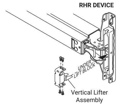
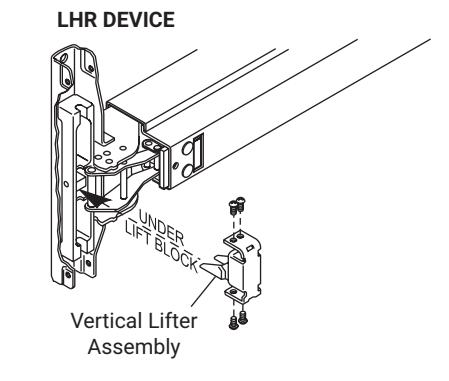
Remove four screws and vertical lifter assembly. Turn device to opposite (180°) orientation, insert lifter assembly and reinstall screws.
NOTE: Lifter must fit <u>under</u> lift block as shown.
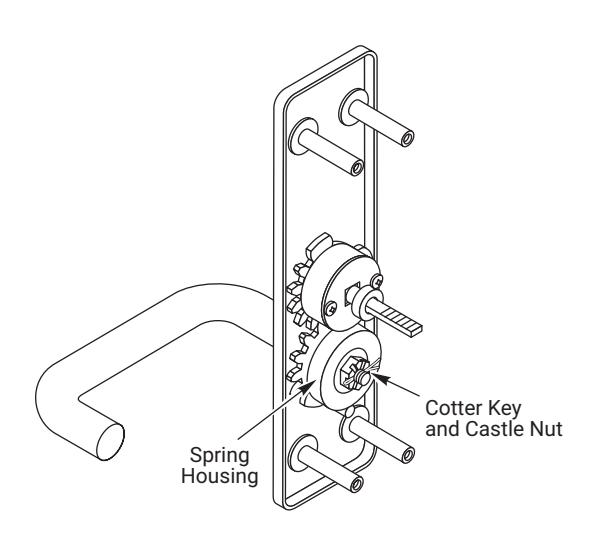
Handing Instructions

Lever Handle Trim
- 1. Remove cotter pin.
- 2. Remove castle nut.
- 3. Observe spring orientation:
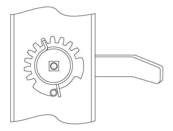
LHR: Red spring (part # 60-7000-1225-999) Short lead is at 1 o'clock and long lead is to lever side of stump at 6 o'clock.
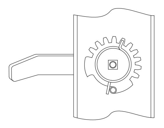
RHR: Blue spring (part # 60-7000-1224-999) Short lead is at 11 o'clock and long lead is to lever side of stump at 6 o'clock.
- 4. Remove round housing, spring and spacer.
- 5. Note orientation of "gap" which governs rotation in gear and remove gear.
- 6. Rotate lever 180°.
- 7. Flip gear over and reinstall, observing proper gap orientation for new direction of rotation:
LHR 6 - 8 o'clock
RHR 4 - 6 o'clock
- 8. Install spring of opposite hand (color). Place spring around spindle with long lead against gear and to lever side of post. Place housing (gap side toward lever) over spring and spindle until square in housing begins to slide down on spindle. While applying downward pressure on housing, wind short lead of spring toward lever until housing snaps into place.
- Replace spacer in housing. Spring, housing and spacer should now be oriented as indicated in step 3 above.
Note: Housing gap will always be to the lever side and spring will be slightly preloaded when properly installed.
- Be sure lever thimble is seated properly in escutcheon. Reinstall nut snugly, but do not over tighten. Lever should rotate freely.
- 11. Replace cotter pin.
Right-Hand Reverse (Blue Spring)
Left-Hand Reverse (Red Spring)
Troubleshooting Guide

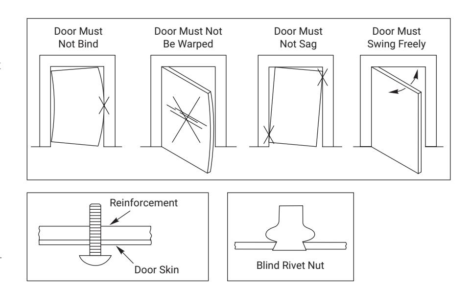
- Many problems with the operation of exit devices are caused by factors other than the device itself. Among the most common is a misalignment or an improper fit of the door within the frame.
- 2. Another common source of problems is improper installation. Even if all cutouts and screw holes are properly located, exit devices must be securely fastened to properly reinforced doors. Hollow doors and frames with a structural thickness (metal skin plus reinforcement, or solid hardwood) must have at least three full screw threads to be considered reinforced.
- Most problems with dogging occur on vertical rod devices. When the dogging function is hard to engage or will not work at all, the rods may be incorrectly adjusted, allowing the mechanism to bottom out. Readjust rods per the device instructions or as outlined on the previous pages.
Notes

The ASSA ABLOY Group is the global leader in access solutions. Every day we help people feel safe, secure, and experience a more open world