ASSA ABLOY ACCENTRA 690F & 691F (Fail Safe , Fail Secure) Series Heavy Duty Electric Trim Control_80-8470-0690-000
Open the original PDF document
View PDF(Fail Safe/Fail Secure) Series Heavy Duty Electric Trim Control (E.T.C.) Installation Instructions With ElectroLynx® Connector System
ACCENTRA
This instruction manual includes wiring instructions for E.T.C. with either Fail Safe or Fail Secure Control Function or Fail Safe or Fail Secure Control Function and Security Monitor (SM). Both these configurations include the ElectroLynx® hinge connector system.
⚠ WARNING
This product can expose you to lead which is known to the state of California to cause cancer and birth defects or other reproductive harm. For more information go to www.P65warnings.ca.gov.
WARNING
Attention Installer: Any retrofit or other field modification to a fire rated opening can potentially impact the fire rating of the opening, and ASSA ABLOY makes no representations or warranties concerning what such impact may be in any specific situation. When retrofitting any portion of an existing fire-rated opening, or specifying and installing a new fire-rated opening, please consult with a code specialist or local code official (Authority Having Jurisdiction) to ensure compliance with all applicable codes and ratings.
80-8470-0690-000 04/24

(Fail Safe/Fail Secure) Series Heavy Duty Electric Trim Control (E.T.C.) Installation Instructions With ElectroLynx<sup>®</sup> Connector System
1. Cylinder Installation
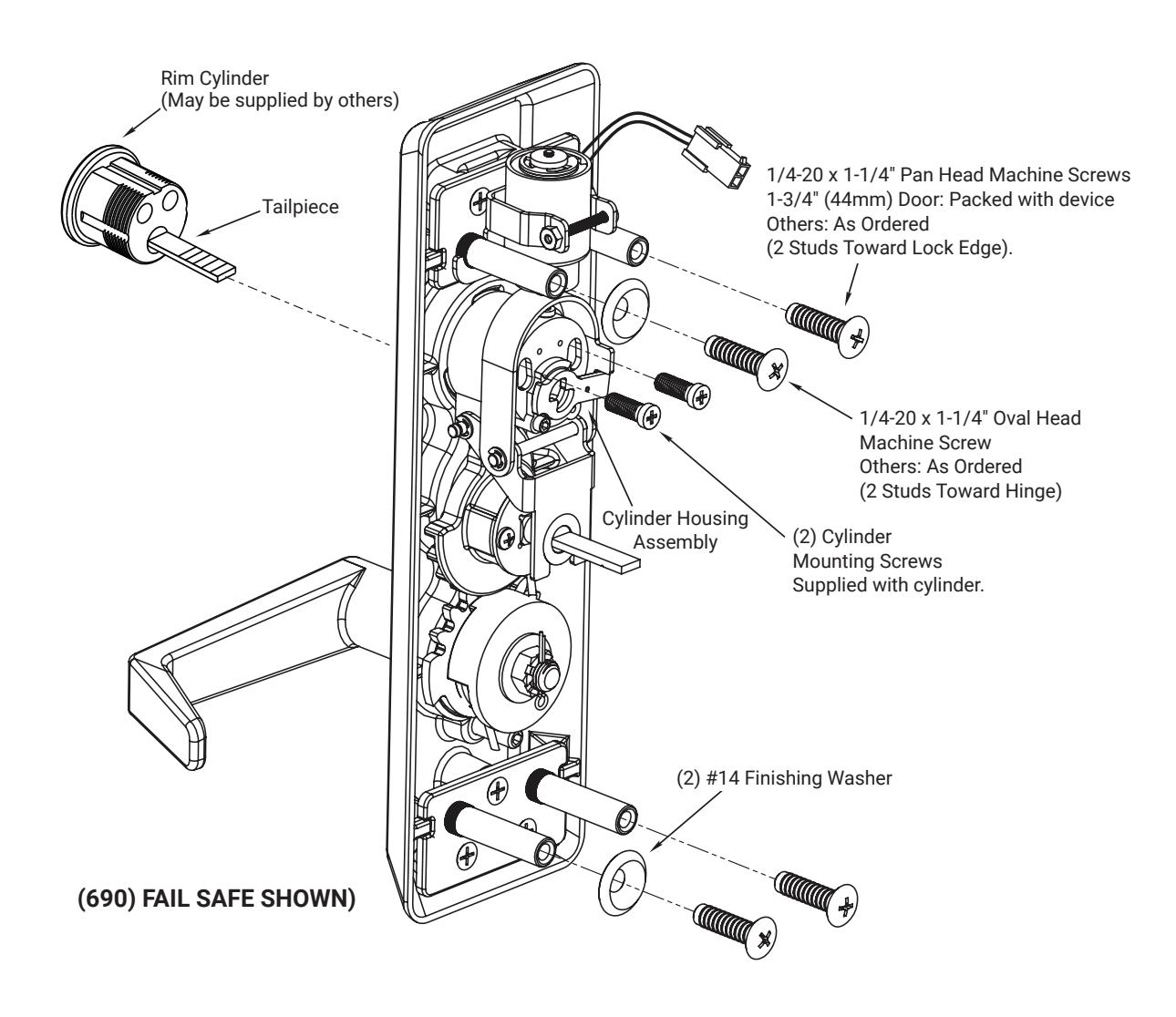
- 1. Check cylinder components. Non-standard cylinder collars and mounting screws supplied with cylinders.
- 2. Pass cylinder thru cylinder collar (when required), escutcheon, and cylinder housing. Tailpiece inserts into slot in cam. Cylinder seats in cylinder housing assembly recess.
- 3. Cut cylinder tailpiece. Correct length; 1/16"(2mm) to 3/16"(5mm) beyond cylinder housing cam.
Installation Notes
- For new applications, a raceway harness with (8) and (4) pin connectors will be pre-installed inside door by ASSA ABLOY door manufacturer when specified during ordering process. Raceway harness kits are available for retrofit applications and for doors manufactured by non-ASSA ABLOY manufacturers.
- If door raceway connectors are not present remove Trim connector.
A. Assembly
- 1. Assemble trim.
- 2. After marking door inside face for device location (Device Instructions), carry "Vertical Reference Centerline" from inside door face. Follow steps 2a and 2b below.
- 3. Carry "Horizontal Reference Centerline" from inside to outside door face.
- 4. Align trim template and tape to door outside face.
- 5. Spot holes and prepare door for trim.
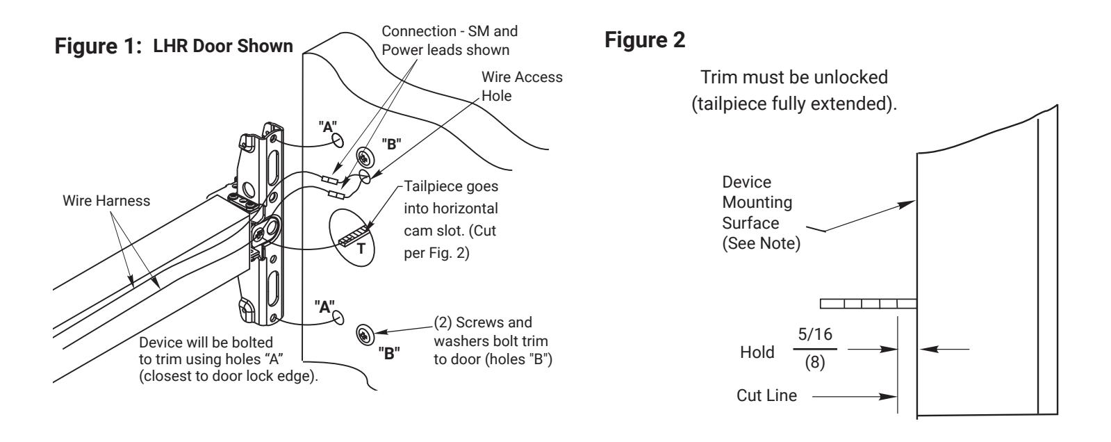
- 6. Pull wire through wire access hole as trim is placed in prep. To avoid wire entanglement in trim mechanism, do not leave excess wire in trim prep. Fasten trim securely using (2) screws and finish washers in holes "B" of Figure 1.
- 7. With trim unlocked (tailpiece turning when lever is moved), cut trim tailpiece as shown in Figure 2. Note: For fail secure trim, apply power before cutting or turn and hold key to extend tailpiece.
- 8. Determine power transfer method; through door or through device. For through device, see "Exit Device Wiring" in the next page. Seat device so that trim tailpiece penetrates cam slot in horizontal position as shown in Figure 1. Continue device mounting as shown in device instructions. Do not install covers until device is wired. Connect trim to wire harness. Refer to Typical Wiring after device has been installed.
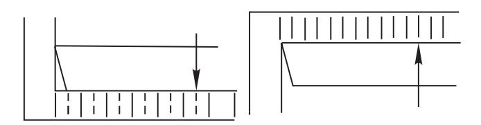
2a. Measure Inside Line Location
2b. Carry Dimension over to outside Face
(Fail Safe/Fail Secure) Series Heavy Duty Electric Trim Control (E.T.C.) Installation Instructions With ElectroLynx<sup>®</sup> Connector System

1. Cylinder Installation
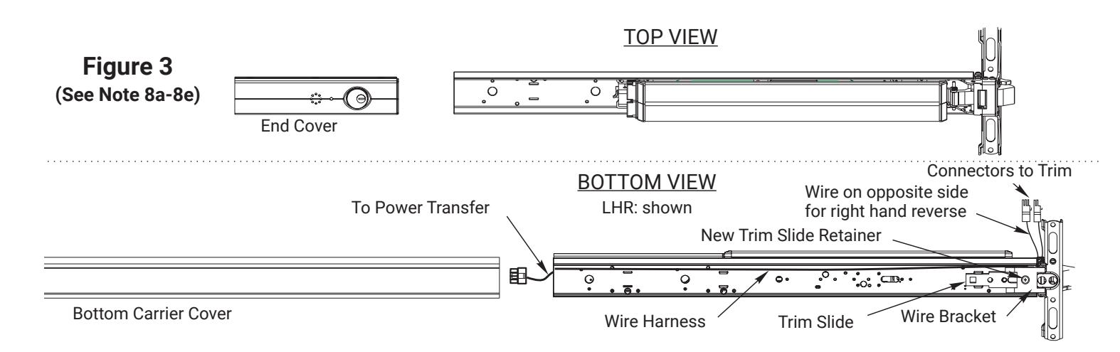
B. Exit Device Wiring (Figure 3)
- 1. Remove end cover and bottom carrier cover.
- 2. Remove trim slide retainer and replace with new retainer.
- 3. Place wire bracket over new trim slide retainer, as shown.
- 4. Place wire harness on the carrier with the plug connector at the latch side of the device. Allow 6"(153mm) for connection to the electric trim. Place the wire harness between the wire bracket and carrier. (LHR SHOWN)
- 5. Replace the carrier cover and rear cover.
80-8470-0690-000 04/24
(Fail Safe/Fail Secure) Series Heavy Duty Electric Trim Control (E.T.C.) Installation Instructions With ElectroLynx<sup>®</sup> Connector System
2. Typical Wiring Instructions
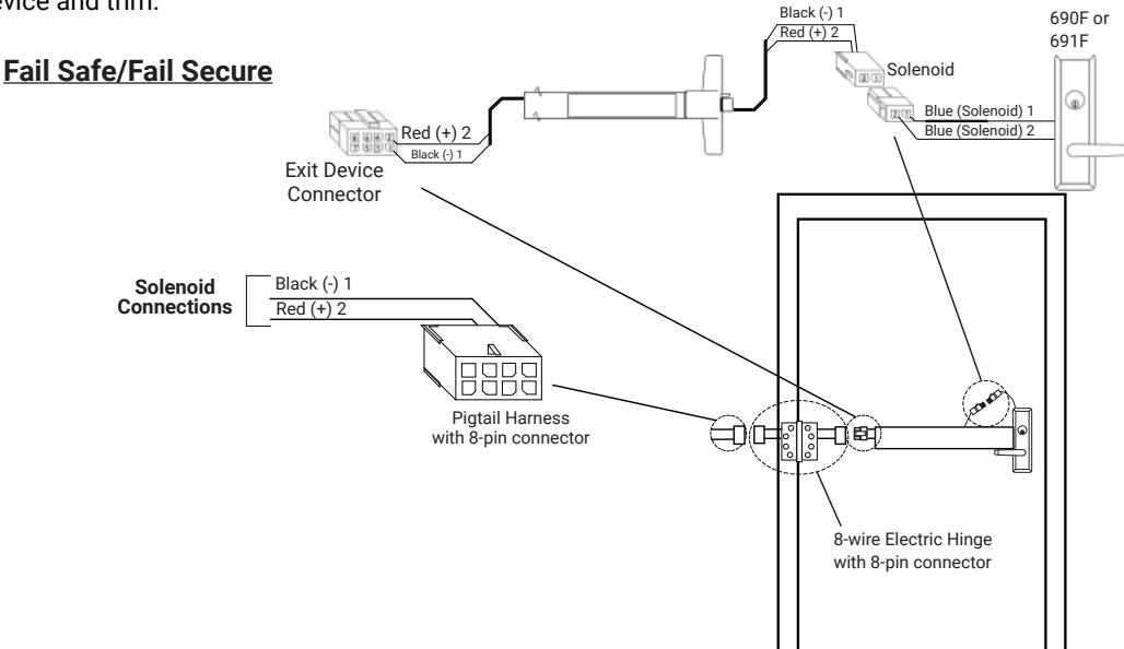
690F & 691F Series E.T.C. With ElectroLynx® Connector System
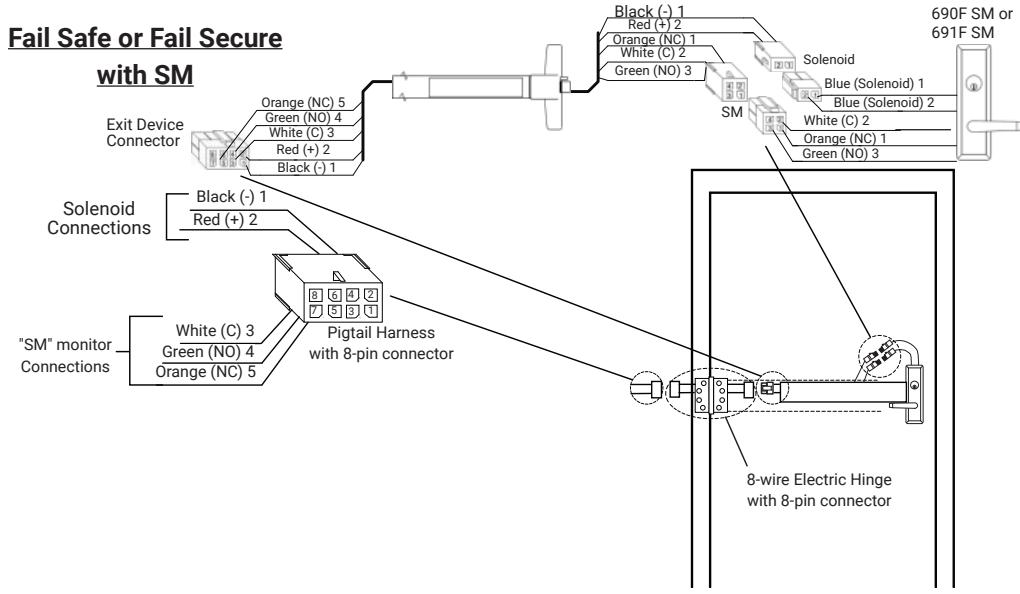
Device, raceway, hinge and pigtail 8-pin terminations and wire colors match.
- 1. Install door, electric hinge, device and trim. Plug hinge and trim connectors into raceway connectors.
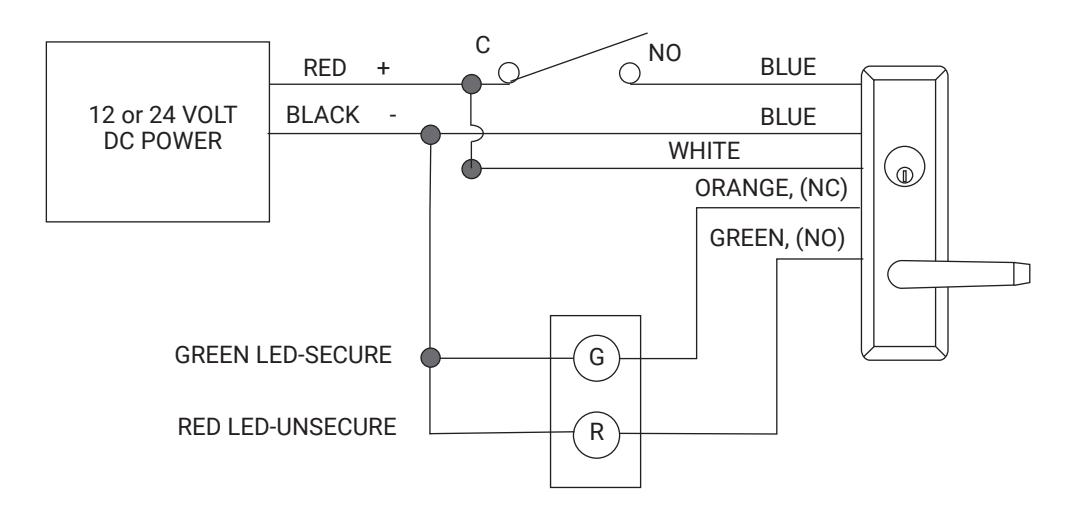
- 2. Wire to pigtail wires as required. Wiring diagram indicates trim in its normal position.
- 3. Plug pigtail connector into electric hinge connector.
- 4. Test device and trim.
Device, raceway, hinge and pigtail 8-pin terminations and wire colors match.
- Install door, electric hinge, device and trim. Plug hinge and trim connectors into raceway connectors.
- 2. Wire to pigtail wires as required. Wiring diagram indicates trim in its normal position.
- 3. Plug pigtail connector into electric hinge connector.
- 4. Test device and trim.
80-8470-0690-000 04/24 Experience a safer
and more open world
1-855-577-5078 Ext. 2 • www.accentra-assaabloy.com
(Fail Safe/Fail Secure) Series Heavy Duty Electric Trim Control (E.T.C.) Installation Instructions With ElectroLynx® Connector System

2. Typical Wiring Instructions
A. Electrical Specifications
690F- Fail Safe Control 691F- Fail Secure Control
0.33A @ 24VDC or 0.61A @ 12VDC models available
Max Monitoring Contact Rating: 4A @ 250 VAC
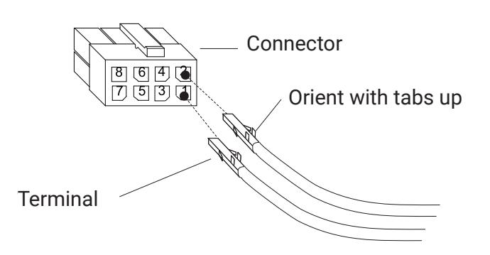
B. Installing Terminals into Connectors
- Plug terminals into connector, see illustration at right. Please note the pin / wire color location and orientation of terminal tabs. Check terminals for proper seating.
- Discard connector if device has connector already installed. Note all wires should terminate in one connector.
690F FAIL SAFE CONTROL WITH SM MONITOR
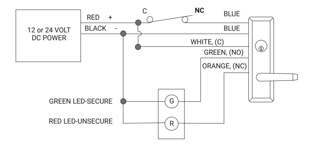
691F FAIL SAFE CONTROL WITH SM MONITOR
80-8470-0690-000 04/24
Experience a safer and more open world
(Fail Safe/Fail Secure) Series Heavy Duty Electric Trim Control (E.T.C.) Installation Instructions With ElectroLynx® Connector System
3. Electric Trim Function
| Function | Function Description |
|---|---|
|
690F
(FAIL SAFE) |
|
|
691F
(FAIL SECURE) |
|
4. Electric Trim Troubleshooting
| Problem | Solution |
|---|---|
| Trim will not retract latchbolt when power is applied (Fail Secure) or when power is removed (Fail Safe). |
|
| Mechanical key will not allow lever to retract latchbolt. |
|
(Fail Safe/Fail Secure) Series Heavy Duty Electric Trim Control (E.T.C.) Installation Instructions With ElectroLynx® Connector System

5. How To Change Hands
NOTES:
- 1. During change ensure black driven gear does not rotate.
- 2. Please wear safety glasses and be aware of spring tension on spring hub upon removal and assembly.
- 3. Light lubrication is recommended under flat gear, white lithium grease can be used.
Tools Needed: Needle Nose pliers, Crescent wrench.
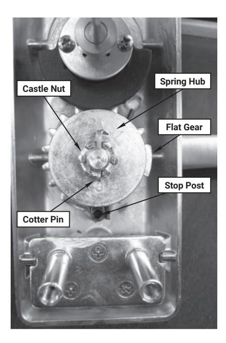
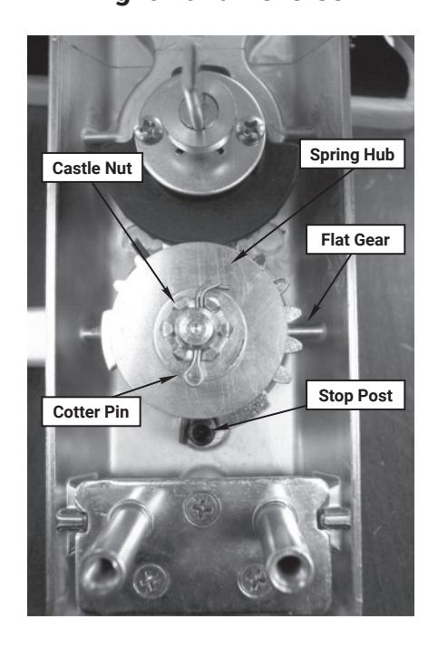
- 1. Remove cotter pin.
- 2. Remove castle nut.
- Remove washer.
- 4. Carefully pull up on spring hub to disengage spring.
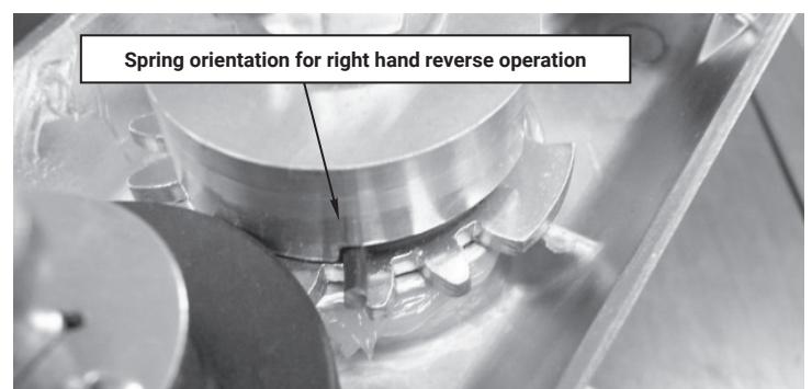
- 5. Remove spring and note orientation.
- 6. Remove lever handle.
- 7. Pick-up flat gear, flip and orient stop on opposite side of stop post. See pictures for orientation.
- 8. Install spring upside down from original orientation and place spring leg on opposite side of stop post from original installation orientation. See pictures for orientation.
Left Hand Reverse
Right Hand Reverse

(Fail Safe/Fail Secure) Series Heavy Duty Electric Trim Control (E.T.C.) Installation Instructions With ElectroLynx® Connector System
5. How To Change hands
- 9. Install lever 180 degrees from original position.
- 10. Install spring hub with stamped number in the 6 o'clock position.
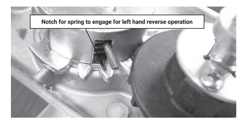
- 11. Rotate spring leg around with needle nose pliers to engage notch in spring hub, refer to pictures for reference position. Press down on spring hub to ensure complete engagement.
- 12. Install washer.
- 13. Install castle nut, do not over tighten, verify by insuring lever returns horizontally on its own.
- 14. Install cotter pin.
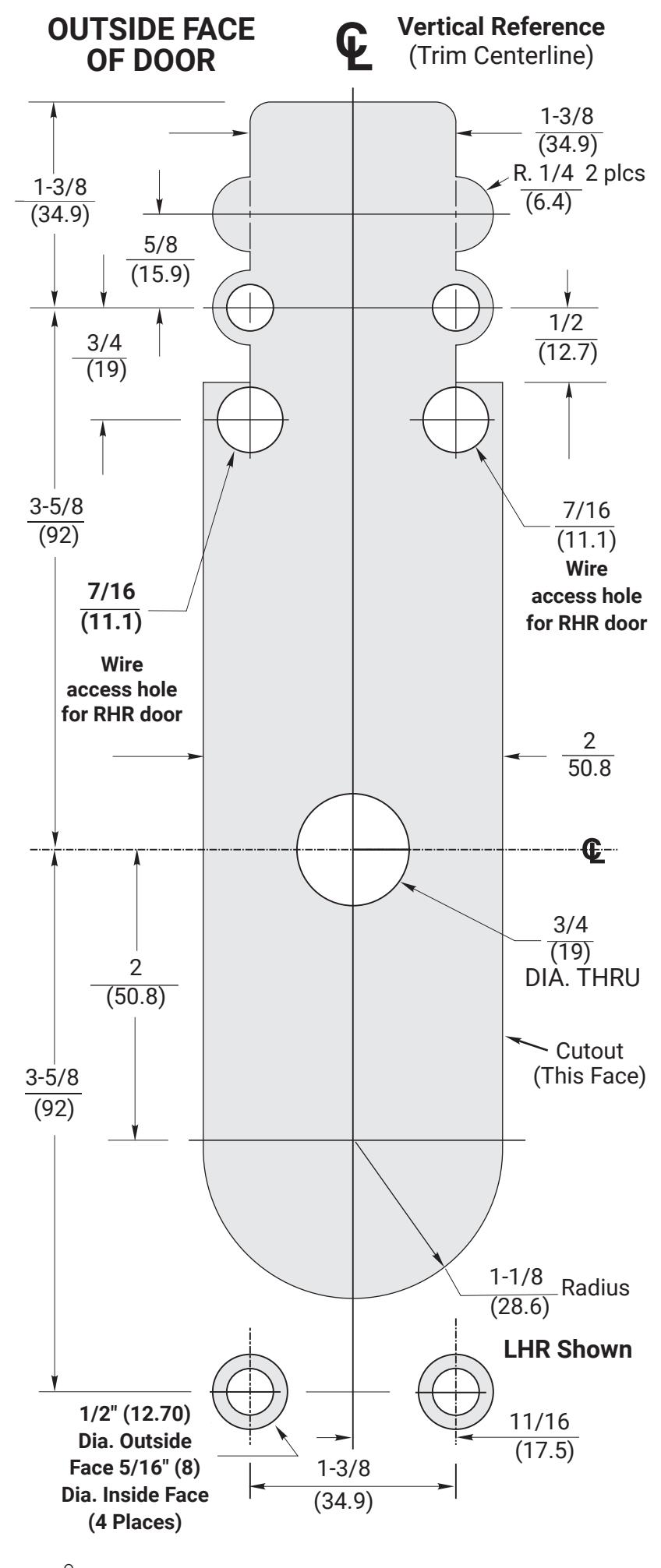
690F & 691F Series Heavy Duty Electric Control Trim Door Marker Template
Dimensions given in Inches (mm)
CAUTION: Office copiers and facsimile machines may change the size of a drawing and make the template inaccurate to use as a door marker. If this is not the original template packed with the trim, use only the dimensions written on the template to locate the holes on the door (do not use the template as a door marker).


(Fail Safe/Fail Secure) Series Heavy Duty Electric Trim Control (E.T.C.) Installation Instructions With ElectroLynx® Connector System
(Fail Safe/Fail Secure) Series Heavy Duty Electric Trim Control (E.T.C.) Installation Instructions With ElectroLynx® Connector System